manuals.online logo
Brands
  1. Home
  2. •
  3. Brands
  4. •
  5. Oppermann Regelgeräte
  6. •
  7. Relay
  8. •
  9. Oppermann Regelgeräte JVA User manual

Oppermann Regelgeräte JVA User manual

Frost protection system JVA/JVS
Temperature and humidity sensors | Data sheet No. 20670 | Version 04-2014 | 1| 4
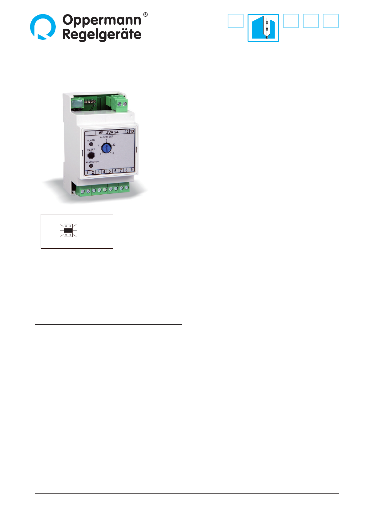
S1
TE 1000
Sensor
S2
S3
* Pt 1000
Ni 1000-LG
*Factory setting
S1 on, S4 off = TE2000
Range setting possible with jumpers.
Jumpers S1 – S3 are located directly behind the front panel,
which is removed from the front.
Jumper S4 is located on the mother board next to the terminal
block.
Technical Data
JVA JVS
Power supply: 24 V AC/DC
Power rating: 2 VA
Alarm setpoint: 0 – +16 °C
Output: 0 – +10 V
Controller input: 0 – +10 V
Sensor input: NI 1000 LG
Starting point of
restriction: 3 °C > alarm 3 – 16 °C
Rate of increase (P range): 2 °C xed 1 – 8 °C
Sensor range
for warming: – 0 – 50 °C
Blower relay
contact load: 6 A, 230 V
Alarm for DDC input: 1 A, 60 V
Ambient temperature: 0 – 40 °C
Dimensions: 53 x 90 x 61 mm (L x W x D)
• 2-phase freeze protection - analog / digital
• Control unit in the control panel
• Average sensor TA-NI1000LG-I-... / TA-PT1000-I-...
or insertion sensor T-NI1000LG-I-... / T-PT1000-I-...
connectible
• Warming and startup circuit for type JVS
• Independent of controller manufacturer
• Temperature-output signal 0 – 10 V
• On short circuit or broken cable →
frost protection status
Applications
The 2-phase frost protection controller is an electronic monitor
for heating registers in ventilation systems to prevent freezing
at low outside temperatures.
Function
When a temperature behind the heating register or the return
ow water drops below a threshold, the control valve (0 – 10 V)
opens as a rst sequence (the green„Restriction“ LED blinks). If
the temperature continues to decline, the second sequence of
the relay switches the blower o (in hardware circuit). The red
LED lights up and the control unit is locked. Reset is only pos-
sible by pressing the internal reset button or by briey cutting
power. An additional relay contact signals„Risk of Freezing“ to
the automation station.
A second potentiometer on type JVS is used to set the warming
temperature to 0 – 50 °C if the blower is switched o. This is also
advantageous when restarting in cold outside temperatures
(startup circuit).
Attention!
The control unit triggers a freeze alarm if the temperature
sensor has a defect, on short circuit or a broken cable: Valve
open – locking – message to DDC. The blower is switched o
during a power outage - the control valve closes.
Frost protection system JVA/JVS
2| 4| Temperature and humidity sensors | Data sheet No. 20670 | Version 04-2014
53,0 mm 53,0 mm
60,5 mm
50,5 mm
90,0 mm 45,0 mm
Dimensioned drawing
Function diagrams
Type JVA 24
0 V
Valve closed
Blower
O Blower
On
Blower
O On
Temp.
xed 3 K
Alarm
Set
0 – 16 °C
Start Point
xed 3 K > Alarm Set
10 V
Valve
Open
0 V
Valve closed
Blower
O Temp.
Alarm
Set
0 – 16 °C
Start Point of
restriction
3 – 16 K
10 V
Valve
Open
Blower On
P band of
restriction 1- 8 K
Type JVS 24
„Blower“ on in
operating mode
0 V
Valve closed Temp.
10 V
Valve
Open
P band of
restriction 1 – 8 K
Standby SP
0 – 50 °C
Type JVS 24
as warming circuit
in the„switched o
mode“
Temperature and humidity sensors | Data sheet No. 20670 | Version 04-2014 | 3| 4
Frost protection system JVA/JVS
12
13
C
Nc
0 – 10 V Out
0 – 10 V In
0 – 10 V
equipotential-
free from blower
relay
to blower relay
from controller
Temp. output 0 – 100 °C
Alarm relay for
DDC controller (DI)
max 60 V, 1 A
Temp. sensor
NI 1000 LG
or PT 1000
Power supply
24 V AC/DC
JVA / JVS
JVS
Control phase to blower
11
10
9
8
7
6
5
4
3
2
1
60



7
C


G0
G0
G
50 mm
37 mm
ø 5 mm
Mounting clamp type MK
Frost protection temperature
monitor, type OPP-FRO
Frost protection temperature sensor
Typ T-NI1000LG-I-... or
Typ T-PT1000-I-...
mounted on water,
side via probe.
Data sheet No. 20900 and 20902
Typ TA-NI1000LG-I-... or
Typ TA-PT1000-I-...
mounted on air side,
with mounting clamps.
Data sheet No. 20906
Mounting clamp
to mount the averaging sensor behind the air heater.
Technical Data
Material: sheetmetal, cadmium-plated
Installation
Measuring the return ow temperature on the water side is the
best solution if the control valve is installed as a distribution
valve with variable water volumes, e.g. also with the possibility
of large Δt. When the objective is to keep water from freezing,
the water must be measured at the coldest location, e.g. in the
return ow.
The welded bushing must be installed in an elbow to allow the
probe to be inserted as far as possible into the interior of the
heat exchanger. If a bushing is already installed in the heating
register (Scandinavia), the insertion sensors are installed here.
A contact sensor can only be used in exceptions.„Alarmset“ is
set to 7 °C on water side applications
Electrical connection
Contacts are shown in operating mode
Technical Data see Data sheet No. 20671
Function check:
Pulling connector 6 – 7 triggers frost alarm for the DDC con-
troller; pulling connector 8 – 9 closes the control valve; pulling
connector 3 – 4 – 5 triggers frost alarm – control valve opens
(10 V output) – blower is switched o (contact 12 – 13 opens) –
red LED lights up, unit is locked.
4| 4| Temperature and humidity sensors | Data sheet No. 20670 | Version 04-2014 Specications subject to change.
Frost protection system JVA/JVS
Oppermann Regelgeräte GmbH | Im Spitzhau 1 | 70771 Leinfelden-Echterdingen, Germany
Phone +49 711 72723560 | Fax +49 711 7280527 | info@oppermann-regelgeraete.de |www.oppermann-regelgeraete.de
Return ow
Bushing
and probe
Installation of air side monitor
Installation of water side sensor
The frost protection temperature monitor is mounted in a
meander shape with the mounting clamps closely behind
the air heater, with direct n contact. The end of the sensor is
held by pushing the bushing in place. To prevent mechanical
damage the sensor must never be permitted to vibrate or utter
due to the airstream.
A 15 mm hole is drilled into the blower and a rubber grommet is
pressed in place as a seal. Carefully insert the sensor probe.
Attention! Do not damage the full length sensor probe insula-
tion, e.g. with sharp edges on components. The soft installation
ange makes the seal. The sensor is active along its full length
and must be kept free of kinks. The blower switches o when
e.g. the temperature drops below the programmed„Alarm set“
value of 16 °C along the entire length of the sensor.
On exterior installations, e.g. on roof-mounted equipment,
ensure that the interface housing and the sensor probe are
located in the heated zone. No location must come into contact
with cold outside air.
The interface head of the water side sensor can be installed in
the open - no special heating is required.
Startup instructions
Startup and adjustments need to be performed with great care
since this involves a safety function that can cause considerable
consequential damages if a malfunction occurs.
We recommend triggering the air side freeze protection device
with freeze spray to be on the safe side and to have tested all
other functions. Triggering with freeze spray does not replace
the described function test.
For water side freeze protection, the sensor resistor is measured
and compared with the resistance table. The system will work
properly if the values are plausible and everything is adjusted
correctly.

This manual suits for next models

1

Popular Relay manuals by other brands

Crouzet HNM manual

Crouzet

Crouzet HNM manual

Advantech PCIE-1760 user manual

Advantech

Advantech PCIE-1760 user manual

Reer AD SR0 Installation, use and maintenance

Reer

Reer AD SR0 Installation, use and maintenance

Dossena DER3BDUAL quick start guide

Dossena

Dossena DER3BDUAL quick start guide

Koncar konpro manual

Koncar

Koncar konpro manual

DEEsys DGF-M10 manual

DEEsys

DEEsys DGF-M10 manual

ERL B-PRO user manual

ERL

ERL B-PRO user manual

GE Multilin 489 instruction manual

GE

GE Multilin 489 instruction manual

Siemens SIRIUS 3SK1 Equipment manual

Siemens

Siemens SIRIUS 3SK1 Equipment manual

Intellitec 00-00803-400 Service manual

Intellitec

Intellitec 00-00803-400 Service manual

urmet domus 788/54 manual

urmet domus

urmet domus 788/54 manual

Pilz PNOZ X2.1VP operating manual

Pilz

Pilz PNOZ X2.1VP operating manual

Moeller easy500 user manual

Moeller

Moeller easy500 user manual

Siemens SIRIUS 3RP15 operating instructions

Siemens

Siemens SIRIUS 3RP15 operating instructions

Siemens SIRIUS 3RA2943-2AA1 Original operating instructions

Siemens

Siemens SIRIUS 3RA2943-2AA1 Original operating instructions

ABB REL 356 quick start guide

ABB

ABB REL 356 quick start guide

GE MOV 2000 instructions

GE

GE MOV 2000 instructions

Crucible Technologies GBR1 Installation and user guide

Crucible Technologies

Crucible Technologies GBR1 Installation and user guide

manuals.online logo
manuals.online logoBrands
  • About & Mission
  • Contact us
  • Privacy Policy
  • Terms and Conditions

Copyright 2025 Manuals.Online. All Rights Reserved.