Unit: inches (mm)
The receiver must be taught this transmitter code before use. Refer to the receiver’s manual for details.
1
Double stick tape installation
Screw installation
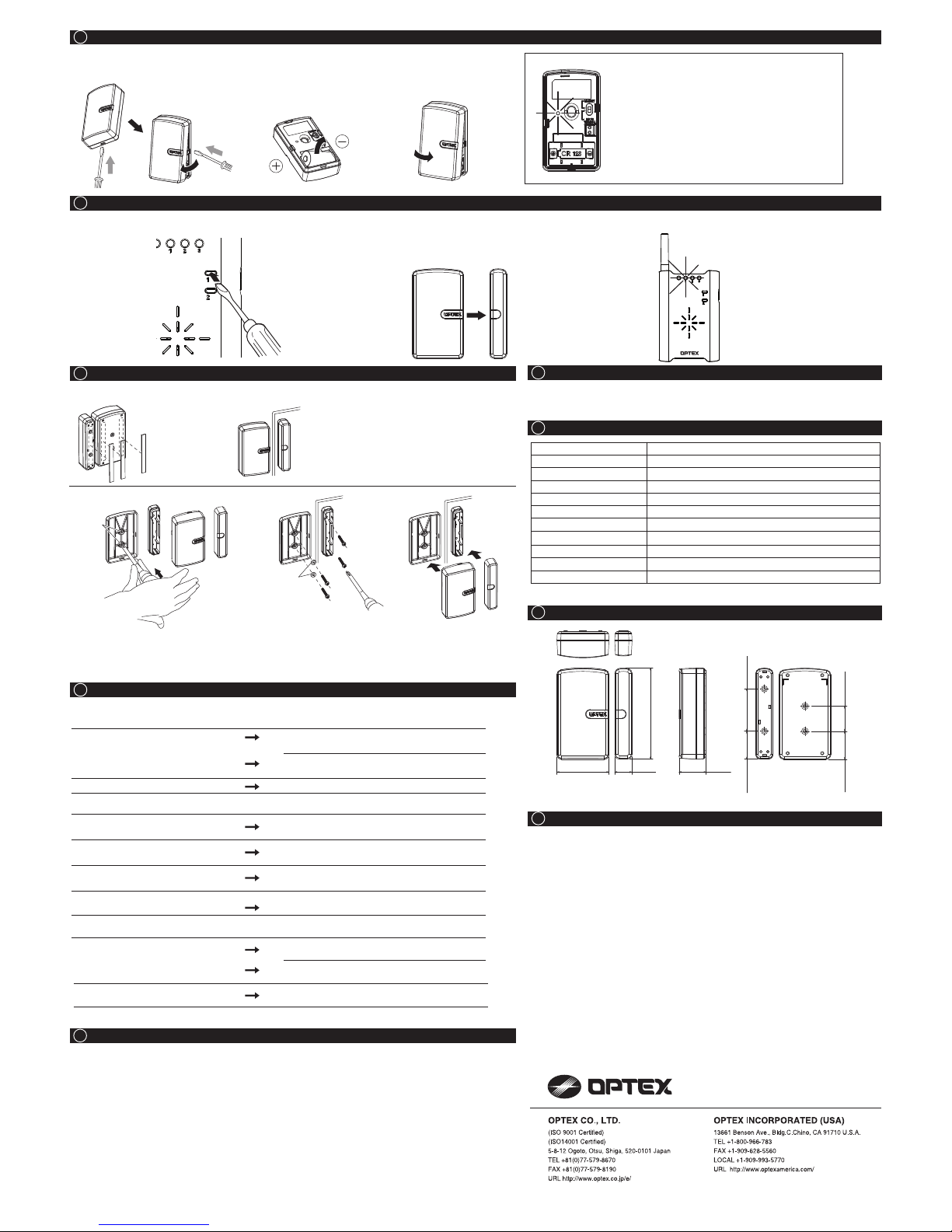
. Preparation
•Press switch 1 of
the receiver until
the power indicator
starts flashing.
•Press switch 2 to
select the zone
you wish to assign
to the sensor.
2. Activation 3. Verification Note:
1. The system is not operating.
Check the transmitter.
Does the status indicator light up when
y
wallplate?
ou remove transmitter unit from
If not, check to see whether the battery is inserted
correctly. Otherwise try a new battery.
Is the status indicator flashing? The battery is old. Replace the battery.
Check the receiver(or repeater).
Is the power indicator of the receiver lit? Is the receiver on? Check the wiring, power switch
and connection.
The receiver does not respond to the TC-
10U.
The TC-10U is not properly recognized by the
receiver. Teach the receiver correctly.
The zone indicator of the receiver is on,
but nothing happens.
The receiver has not been properly setup. Refer to
the receiver’s manual and verify the setting.
Is there anything blocking the
transmission?
Relocate the receiver and/or the TC-10U. Metal
objects can shorten the effective transmission range.
2. The system is not operating correctly.
It does not transmit.
Before contacting the supplier! Remove the battery, then reinsert the new
batteries and verify the TC-10U’s operation again.
•If the above solutions do not work, please contact your supplier for services.
Model
Description
Status Indicator
Power Source
Battery Life
F
Input terminal Our battery operated detector only
requency
Operating Temp.
Installation Location
Weight
TC-10U
Door/ Window Transmitter
Red LED
3V: CR123 lithium battery (not include)
Approx. 2 years [100 times per day at 70°F (20°C)]
418MHz
15°F ~ 120°F (-10°C ~ +50°C)
Indoor/ Outdoor where don’t have rain direct
Accessories
2.5 oz (70g) (not included battery)
Double Stick Tape x 3, Screw x 4, Rubber Washer x 2
Specifications may change without notice
5 INSTALLATION BATTERY
6 TEACH TRANSMITTER CODES TO THE RECEIVER
7 INSTALLATION
11 TROUBLESHOOTING
9SPECIFICATIONS
8CONFIRMATION
10 DIMENSIONS
12 WARRANTY
13 COMPLIANCE
• When the power is low, status indicator starts
to flash. Replace the battery in such case
even if it is less than a year old.
• Low power may become the cause of false
alarm.
• There is no need to learn the TC-10U nor the
receiver after replacing battery.
NOTE :Don’t throw the battery in the fire.
This may cause the explosion hazard.
1. This product is warranted under normal use for 1 year from the date of purchase. If the
product proves to be defective, return it with a copy of your dated sales receipt for repairs
or replacement without charge.
2. The warranty is not applicable when below circumstances will be found:
• Mechanical or electrical modification(s) are made to the product or it is otherwise altered
manually.
• The product is already been serviced at place(s) other than the manufacturer.
• It is determined that the product malfunction has resulted from improper use or from an
accident.
• No copy of the dated sales receipt has been submitted together with the product to be
serviced.
FCC ID : DC9TC-10U
The changes or modifications not expressly approved by the OPTEX could void the user’s authority to operate the equipment.To comply with
the FCC RF exposure compliance requirements, this device and its antenna must not be co-located or operating to conjunction with any
other antenna or transmitter.Note: This equipment has been tested and found to comply with the limits for a Class B Digital Device, pursuant
to part 15 of the FCC Rules. These limits are designed to provide reasonable protection against harmful interference in a residential
installation. This equipment generates, uses and can radiate radio frequency energy and, if not installed and used in accordance with the
instruction, may cause harmful interference to radio communication. However, there is no grantee that interference will not occur in a
particular installation. If this equipment does cause harmful interference to radio or television reception, which can be determined by turning
the equipment off and on , the user is encouraged to try to correct the interference by one or more of the following measures.(1)Reorient or
relocate the receiving antenna.(2)Increase the separation between the equipment and receiver.(3)Connect the equipment into an outlet on a
circuit different from that to which the receiver is connected.(4)Consult the dealer or an experienced radio/TV technician for help.
IC : 4012A-000000TC10U
Operation is subject to the following two conditions.(1)this device may not cause interference, and (2) this device must accept any
interference, including interference that may cause undesired operation of the device.
To reduce potential radio interference to other users, the antenna type and its gain should be so chosen that the equivalent isotropically
radiated power (e.i.r.p.) is not more than that permitted for successful communication.
2. Insert Battery.
Observe polarity.
(+/- direction)
3. Install the Front cover.
Be sure to close securely.
1. Remove the Front cover as
shown.
• Verify that the receiver has
learned successfully by
observing the zone
indicators of the receiver.
Zone indicators should
have stopped flashing and
remain continuously on.
• Separate the magnet unit from transmitter unit. • After teaching all the
transmitter codes (if you
have multiple transmitters),
return the receiver to
normal operating status.
• Make sure that the receiver
operates correctly with all
the transmitters.
5917040
Don’t put the magnet unit close
to transmitter unit until you are
ready to teach the receiver.
Unwanted detection can cause
the TC-10U to be assigned to
the wrong zone and override
the data of other transmitters.
After installation, open and close door/ window and confirm the reception of the
transmission signal on the receiver side.
Door/
Window
Wall
Door/
Window
Wall
Rubber
washer
Knockout
Place the double
stick tape as
shown.
Clean the installation positions before
installing them.
Install the transmitter unit on the wall.
Install the magnet unit on the door or window.
* Align the magnet unit within 0.2 inch (5 mm).
Install the back cover.
Install magnet on the door or window with mounting screws.
* Without the use of rubber washers, the unit will lose its weatherproof rating.
* Align the magnet unit within 0.2 inch (5mm).
Put back the cover.
1.8 (45) 0.6 (15)
3.1 (79)
0.85 (21.7)0.95 (24.2)
0.95 (24.2) 1.5 (36.7)
1.0 (24)
Is the magnet unit away by enough distance?
Please separate it by 2.36 inch (60mm).
Check if the distance between transmitter unit and
magnet unit within 0.2 inch (5mm).
Is the distance between TC-10U and receiver too
far? Please use repeater.