Optica P218Z User manual

002C72XWZ1A5
Full HD PTZ IP Camera
Menu Tree
Model: P218Z
Ver. 1.5

1
Table of Contents
1.Overview.................................................................................................................................. 3
2.Menu Tree................................................................................................................................ 4
2.1Home Page ................................................................................................................... 5
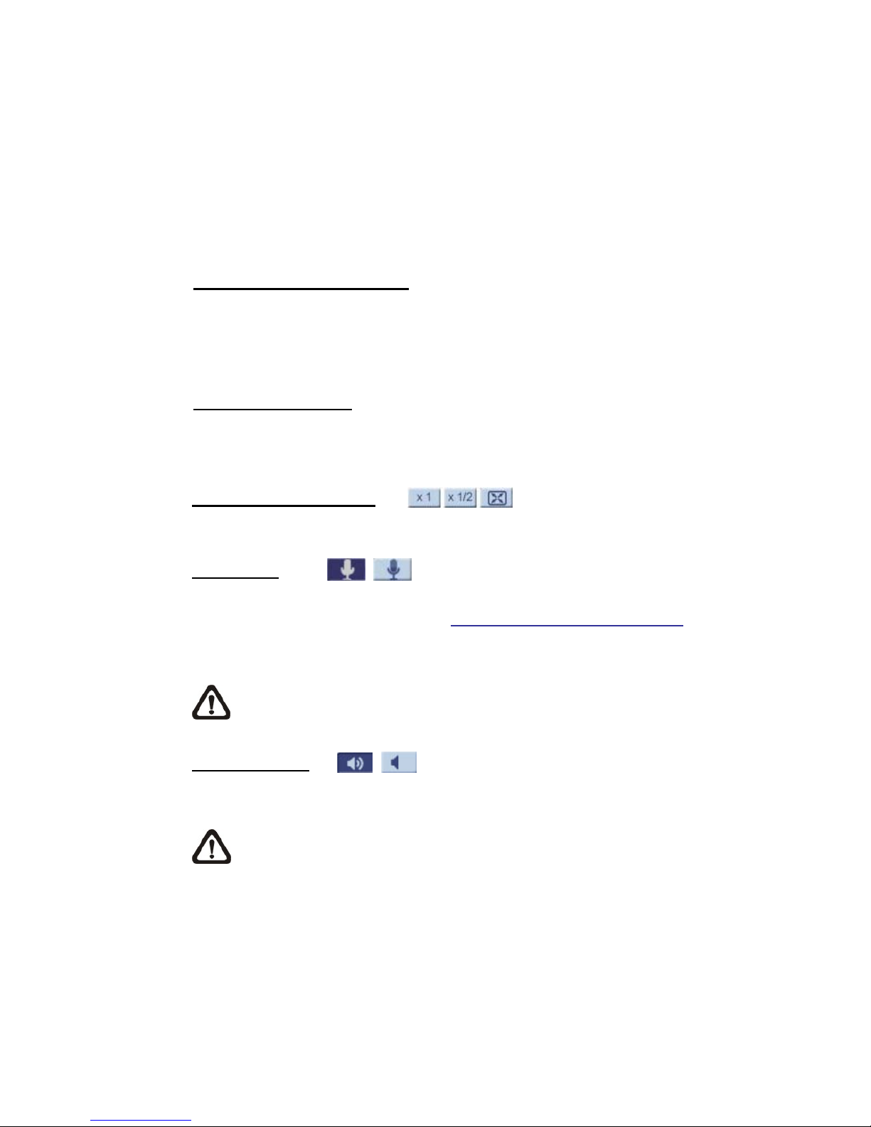
2.1.1Function Items on Home Page ...................................................................... 5
2.2System .......................................................................................................................... 9
2.2.1System........................................................................................................... 9
2.2.2Security........................................................................................................ 11
2.2.3Network........................................................................................................ 16
2.2.4DDNS........................................................................................................... 21
2.2.5Mail .............................................................................................................. 21
2.2.6FTP.............................................................................................................. 22
2.2.7HTTP ........................................................................................................... 22
2.2.8Application (Alarm Settings) ........................................................................ 23
2.2.9Motion Detection.......................................................................................... 29
2.2.10Network Failure Detection ........................................................................... 34
2.2.11Storage Management (Local Recording)..................................................... 36
2.2.12 Recording (Local Recording)....................................................................... 38
2.2.13Schedule...................................................................................................... 39
2.2.14File Location (Snapshots and Web Recording) ........................................... 40
2.2.15View Information .......................................................................................... 40
2.2.16Factory Default ............................................................................................ 42
2.2.17Software Version ......................................................................................... 42
2.2.18Software Upgrade........................................................................................ 43
2.2.19Maintenance ................................................................................................ 44
2.3Streaming .................................................................................................................... 45
2.3.1Video Format (Video Resolution / Video Deinterlace) ................................. 45
2.3.2Video Compression ..................................................................................... 47
2.3.3Video OCX Protocol..................................................................................... 48
2.3.4Video Frame Rate........................................................................................ 48
2.3.5Audio (Audio Mode and Bit Rate Settings) .................................................. 49
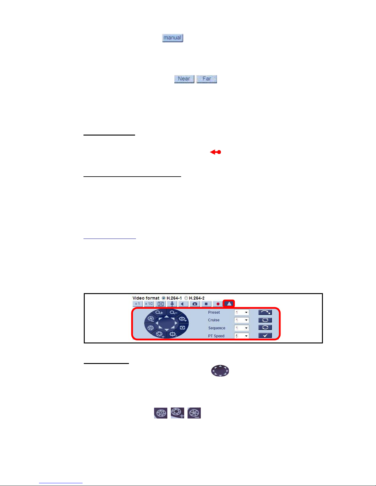
2.4PTZ.............................................................................................................................. 50
2.4.1Preset .......................................................................................................... 50
2.4.2Cruise .......................................................................................................... 51
2.4.3Auto Pan ...................................................................................................... 52
2.4.4Sequence .................................................................................................... 53
2.4.5Home ........................................................................................................... 55
2.4.6Tilt Range .................................................................................................... 56
2.4.7Camera— Privacy Mask.............................................................................. 56

2
2.4.8Camera— Exposure .................................................................................... 58
2.4.9Camera—WB (White Balance) .................................................................... 59
2.4.10Camera—Misc 1 (Miscellaneous Setups Menu 1)....................................... 60
2.4.11Camera—Misc 2 (Miscellaneous Setups Menu 2)....................................... 62
2.4.12Camera- Default .......................................................................................... 63
2.5Logout ......................................................................................................................... 63
Appendix A: Install UPnP Components...................................................................................... 64

3
1. Overview
The Optica P218Z HD Speed Dome IP Camera transmits digital video and audio
data using wire connection. Live video can be monitored and recorded from
window-based computer via network.
The video encoder supports real-time Main Profile H.264 Full HD resolution.
Simultaneous dual streams, H.264/H.264 and H.264/MJPEG, are available for
various network applications via speeding or limited bandwidth. Better image
quality and high resolution are delivered by IP support. It eliminates the
“combing” effect due to scene change and performs more stabilized image.
With IP solution, multiple and authorized users can view the immediate image
from any location through network even using a standard web-browser. It
enables users to access and remote the camera without at specific locations.

4
2. Menu Tree
There are five setting tabs including <Home>, <System>, <Streaming>, <PTZ>
and <Logout>.
Home
Users can monitor live video of the targeted area.
System setting
The Administrator can set host name, system time, root password, network
related settings, etc. Further details will be interpreted in the section System.
Streaming setting
The Administrator can modify video resolution and rotate type and select video
compression mode in this page.
PTZ setting
Users are allowed to program Preset Point(s), Cruise Line(s), Auto Pan Path(s)
and Sequence Line(s) via PTZ controls, and adjust various camera parameters
including Auto Exposure (AE), White Balance (WB), Back Light Compensation
(BLC), Sharpness, Exposure Compensation, Digital Zoom, etc.
Logout
Click on the tab to re-login the IP Camera with another username and
password.

5
2.1 Home Page
Click on the tab <Home> to access the Home Page. There are several function
buttons on the Home page. Detailed information of each item is as described in
the following chapter.
2.1.1 Function Items on Home Page
Multiple Languages Support
Multiple languages are supported, including German, English, Spanish, French,
Italian, Korean, Simplified Chinese, Russian, etc. for the viewer window
interface.
Digital Zoom Control
In the full screen mode, users can implement digital PTZ by rotating the mouse
wheel (for zoom in / out), and drag the mouse into any direction.
Screen Size Adjustment
Image display size can be adjusted to x1/2 and full screen.
Talk button (on / off)
Talk function allows the local site talks to the remote site. Click on the button to
switch it to on / off. Please refer to Security: Add user > Talk/Listen for further
details.
NOTE: This function is only available for User who has granted this
privilege by the Administrator.
Speaker button (on / off)
Click on the <Speaker> button to mute / activate the audio.
NOTE: This function is only available for User who has granted this
privilege by the Administrator.

6
Snapshot button
Click on the button and the JPEG snapshots will automatically be saved in the
appointed place. The default place of saving snapshots is: C:\. To change the
storage location, please refer to File Location for further details.
NOTE: For users with Windows 7 operating system, it is required to log
on as an Administrator to implement the Web Recording function.
Video Streaming Pause / Restart button (pause / restart)
Click on the <Stop> button to disable video streaming, the live video will be
displayed as black. Press the <restart> button to show the live video again.
Web Recording button (on / off)
Click on the <Recording> button and the Live View through the web browsing
will be directly recorded to the specific location on the local hard drive, which
could be configured in the <File Location> page. The default storage location for
the web recording is: C:\. Please refer to File Location for further details.
NOTE: For users with Windows 7 operating system, it is required to log
on as an Administrator to implement the Web Recording function.
Control Panel Button (close / open)
Click on the <Control Panel> button to open and close the Control Panel on the
homepage.
Zoom Adjustment (Wide / Tele)
Click on the buttons <Wide / Tele> to control zoom in / out. Or move the cursor
closely onto the zoom adjustment bar to the desired zoom ratio.
Focus Adjustment
zAuto Focus (Continuous AF)
Click on the <Auto> button to enable AF mode. In this mode, the camera
will keep in focus automatically and continuously regardless of zoom
changes or any view changes. The Focus status will also be displayed
above the live video pane as shown below.

7
zManual button
Click on the <Manual> button, and users can adjust focus manually via
Near / Far buttons.
zNear / Far buttons
Click on the <Manual> button first, and users can adjust focus manually
via <Near> and <Far> buttons. The status will also be displayed above
the screen as shown below.
Pan/Tilt Control
Users can implement pan/tilt control by first moving the cursor to the live video
pane; then left click and drag the pointer in any direction.
Optical / Digital Zoom Control
In Normal View display mode, users can implement zoom in / out by first moving
the cursor to the live video pane and then rotating the mouse wheel. As in Full
Screen mode, users can directly rotate the mouse wheel to zoom in / out on the
image. Digital zoom is only available when the function is activated and which is
set in <Camera-Misc1> page under the <PTZ> tab; refer to the Section
Camera—Misc 1 for details. When the camera reaches the limit of its optical
range, it will automatically switch to digital zoom.
Furthermore, after clicking the <Control Panel> Button, the Control Panel will be
shown as the figure below.
Control Panel
zPan & Tilt Direction Control
The <Pan and Tilt Direction Control> on the Control Panel allows users
to control the Camera with browser viewers other than IE.
zIris Control (Auto Iris / Iris+ / Iris-)
Click on the buttons (Auto Iris / Iris+ / Iris-) to adjust the Iris parameters.

8
zZoom (Zoom In / Zoom Out)
Click on the buttons to zoom in or zoom out.
zFocus (Auto Focus / Focus Near / Focus Far)
Click on the buttons to adjust the focus as near, far or automatic.
Run Preset / Cruise / Sequence
After setup the Preset / Cruise / Sequence lines according to PTZ Settings,
select a Preset / Cruise / Sequence line and start it by clicking on the <Run>
button ( / / ).
PT Speed (1~10)
Set a number between 1 and 10 as the PT Speed every time users pan or tilt
the Camera via the Pan & Tilt Direction Control Panel. 1 is the slowest, 10 is the
fastest.
Set Center Mode
Right click on the Live Video Pane and select <Set Center Mode>. Then users
can position the interest area in the center of the Live Video Pane automatically
by clicking on the point of interest. In <Set Center Mode>, right click on the Live
Video Pane again and select <Set Emulated Joystick Mode> to return to control
the Camera direction by left clicking and dragging the pointer on the Live
Video Pane.

9
2.2 System
Under the tab <System>, there are categories as the table below:
System
System
Security
Network
DDNS
Mail
FTP
HTTP
Application
Motion Detection
Network Failure Detection
Storage Management
Recording
Schedule
File Location
View Information
Factory Default
Software Version
Software Upgrade
Maintenance
NOTE: The System configuration page is only accessible by the
Administrator.
2.2.1 System
The System Setting can be found under the path: System> System.
Host Name
The name is for camera identification. If alarm function is enabled and is set to
send alarm message by Mail / FTP, the host name entered here will display in
the alarm message.
Time Zone
Select the time zone from the drop-down menu.
Enable Daylight Saving Time
To enable DST, please check the item and then specify time offset and DST
duration. The format for time offset is [hh:mm:ss]; for instance, if the amount of
time offset is one hour, please enter “01:00:00” into the field.

10
Time format
Choose a time format (yyyy/mm/dd or dd/mm/yyyy) from the drop-down menu.
The time format for “PC date” under <Sync with Computer Time> and “Date”
under <Manual> will be changed according to the selected format.
Sync with Computer Time
Select the item and video date and time display will synchronize with the PC’s.
NOTE: Users MUST click on the <Save> button to confirm the setting.
Otherwise the time will not be synced.
Manual
The Administrator can set video date, time and day manually. Entry format
should be identical with that shown next to the center field.
Sync with NTP Server
Network Time Protocol (NTP) is an alternate way to synchronize the camera’s
clock with a NTP server. Please specify the server that is wished to synchronize
in the center field. Then select an update interval from the drop-down menu. For
further information about NTP, please see the web site: www.ntp.org.
NOTE: The synchronization will be done every time the camera boots
up.

11
2.2.2 Security
The Security setting can be found under this path: System> Security.
Click the Security category, there will be a drop-down menu with tabs including
<User>, <HTTPS>, <IP Filter>, and <IEEE 802.1X>.
2.2.2.1 User
The User setting can be found under this path: System> Security> User.
Admin Password
Change the administrator’s password by inputting the new password in both text
boxes. The input characters/numbers will be displayed as dots for security
purposes. After clicking on <Save>, the web browser will ask the Administrator
for the new password for access. The maximum length of the password is 14
digits.
NOTE: The following characters are valid: A-Z, a-z, 0-9, !#$%&’-.@^_~.
Add user
Type the new user's name and password and click on <Add> to add the new
user. Both user name and password can be up to 16 characters. The new user
will be displayed in the user name list. There is a maximum of twenty user
accounts. Each user can be assigned the privileges of <Camera control>,
<Talk> and <Listen>.
zI/O access
This item supports fundamental functions that enable users to view
video when accessing to the camera.
zCamera control
This item allows the appointed User to change camera parameters on
the Camera Setting page.
zTalk/Listen
Talk and Listen functions allow the appointed user in the local site (PC
site) communicating with, for instance, the administrator in the remote
site.

12
Manage User
zDelete user
To delete a user, select the user name that is wished like to delete from
the drop-down user list and then click on <Delete> to remove it.
zEdit user
Select a user name from the drop-down user list and click on <Edit> to
edit the user’s password and privilege.
NOTE: It is required to enter the User password as well as select the
function open to the user. When finished, click on <Save> to modify the
account authority.
2.2.2.2 HTTPS
The HTTPS setting can be found under this path: System> Security> HTTPS.
<HTTPS> allows secure connections between the IP Camera and web browser
using <Secure Socket Layer (SSL)> or <Transport Layer Security (TLS)>, which
ensure camera settings or Username / Password info from snooping. It is
required to install a self-signed certificate or a CA-signed certificate for
implementing <HTTPS>.
To use HTTPS on the IP Camera, a HTTPS certificate must be installed. The
HTTPS certificate can be obtained by either creating and sending a certificate
request to a Certificate Authority (CA) or creating a self-signed HTTPS
certificate, as described below.
Create Self-signed Certificate
Before a CA-issued certificate is obtained, users can create and install a
self-signed certificate first.
Click on <Create> button under “Create self-signed certificate” and provide the
requested information to install a self-signed certificate for the IP Camera.
Please refer to the last part of this section: Provide the Certificate Information for
more details.
NOTE: The self-signed certificate does not provide the same high level
of security as when using a CA-issued certificate.

13
Install Signed Certificate
Click on the <Create Certificate Request> button to create and submit a
certificate request in order to obtain a signed certificate from CA.
Provide the request information in the create dialog. Please refer to the
following Provide the Certificate Information for more details.
When the request is complete, the subject of the Created Request will be shown
in the field. Click on <Properties> below the Subject field, copy the
PEM-formatted request and send it to the selected CA.
When the signed certificate is returned, install it by uploading the signed
certificate.
Provide the Certificate Information
To create a Self-signed HTTPS Certificate or a Certificate Request to CA,
please enter the information as requested:
Create Self Signed Certificate Create Certificate Request
Country √√
State or Province √√
Locality √√
Organization √√
Organizational Unit √√
Common Name √√
Valid Day √-
zCountry
Enter a two-letter combination code to indicate the country the certificate
will be used in. For instance, type in “US” to indicate United States.
zState or province
Enter the local administrative region.
zLocality
Enter other geographical information.
zOrganization
Enter the name of the organization to which the entity identified in
“Common Name” belongs.

14
zOrganization Unit
Enter the name of the organizational unit to which the entity identified in
“Common Name” belongs.
zCommon Name
Indicate the name of the person or other entity that the certificate
identifies (often used to identify the website).
zValid days
Enter the period in days (1~9999) to indicate the valid period of
certificate.
Click on <OK> to save the Certificate Information after complete.
2.2.2.3 IP Filter
The IP Filter setting can be found under this path: System> Security> IP Filter.
Using the IP filter, access to the IP Camera can be restricted by denying /
allowing specific IP addresses.
zEnable IP Filter
Check the box to enable the IP Filter function. Once enabled, the listed
IP addresses (IPv4) will be allowed / denied access to the IP Camera.
Select <Allow> or <Deny> from the drop-down list and click on the
<Apply> button to determine the IP Filter behavior.
zAdd / Delete IP Address
Input the IP address and click on the <Add> button to add a new filtered
address.
The Filtered IP Addresses list box shows the currently configured IP
addresses. Up to 256 IP address entries may be specified.
To remove an IP address from the list, please select the IP and then
click the <Delete> button.

15
2.2.2.4 IEEE 802.1X
The IEEE 802.1X setting can be found under this path: System> Security>
IEEE 802.1X.
The IP Camera is allowed to access a network protected by 802.1X/EAPOL
(Extensible Authentication Protocol over LAN).
Users need to contact with the network administrator for gaining certificates,
user IDs and passwords
CA Certificate
The CA certificate is created by the Certification Authority for the purpose of
validating itself. Upload the certificate for checking the server’s identity.
Client Certificate / Private Key
Upload the Client Certificate and Private Key for authenticating the IP Camera
itself.
Settings
zIdentity
Enter the user identity associated with the certificate. Up to 16
characters can be used.
zPrivate Key Password
Enter the password (maximum 16 characters) for user identity.
Enable IEEE 802.1X
Check the box to enable IEEE 802.1X.
Click on <Save> to save the IEEE 802.1X / EAP- TLS setting.

16
2.2.3 Network
The Network setting can be found under this path: System> Network.
Click on the <Network> category, there will be a drop-down menu with tabs
including <Basic>, <QoS>, <SNMP>, and <UPnP>.
2.2.3.1 Basic
The Basic setting can be found under this path: System> Network> Basic.
Users can choose to connect to the IP Camera with fixed or dynamic (DHCP) IP
address. The IP Camera also provides PPPoE support for users who connect to
the network via PPP over Ethernet (PPPoE).
General
zGet IP address automatically (DHCP)
The camera’s default setting is <Use fixed IP address>. Please refer to
User’s Manual for login with the default IP address.
If select <Get IP address automatically>, after the IP Camera restarts,
users can search it through the installer program: DeviceSearch.exe,
which can be found in “DeviceSearch” folder in the supplied CD.
NOTE: Please make the record of the IP Camera’s MAC
address, which can be found in the label of the camera, for
identification in the future.
zUse fixed IP address
To setup static IP address, select <Use fixed IP address> and move the
cursor to the IP address blank and insert the new IP address, ex.
192.168.7.123; then go to the Default gateway (explained later) blank
and change the setting, ex. 192.168.7.254. Press <Save> to confirm the
new setting.
When using static IP address to login to the IP Camera, users can
access it either through “DeviceSearch” software (refer to User’s Manual)
or input the IP address in the URL bar and click on <Enter>.

17
¾IP address
This is necessary for network identification.
¾Subnet mask
It is used to determine if the destination is in the same subnet. The
default value is “255.255.255.0”.
¾Default gateway
This is the gateway used to forward frames to destinations in
different subnet. Invalid gateway setting will fail the transmission to
destinations in different subnet.
¾Primary DNS
Primary DNS is the primary domain name server that translates
hostnames into IP addresses.
¾Secondary DNS
Secondary DNS is a secondary domain name server that backups
the primary DNS.
Use PPPoE
For the PPPoE users, enter the PPPoE Username and Password into the fields,
and click on the <Save> button to complete the setting.
Advanced
zWeb Server port
The default web server port is 80. Once the port is changed, the user
must be notified the change for the connection to be successful. For
instance, when the Administrator changes the HTTP port of the IP
Camera whose IP address is 192.168.0.100 from 80 to 8080, the user
must type in the web browser “http://192.168.0.100:8080” instead of
“http://192.168.0.100”.
zRTSP port
The default setting of RTSP Port is 554; the setting range is from 1024
to 65535.
zMJPEG over HTTP port
The default setting of MJPEG over HTTP Port is 8008; the setting range
is from 1024 to 65535.

18
zHTTPS port
The default setting of HTTPS Port is 443; the setting range is from 1024
to 65535.
NOTE: Be aware to choose the different port from the one set for the
web server port.
IPv6 Address Configuration
With IPv6 support, users can use the corresponding IPv6 address for browsing.
Enable IPv6 by checking the box and click on <Save> to complete the setting.
2.2.3.2 QoS
The QoS (Quality of Service) setting can be found under this path: System>
Network> QoS.
QoS allows providing differentiated service levels for different types of traffic
packets, which guarantees delivery of priority services especially when network
congestion occurs. Adapting the Differentiated Services (DiffServ) model, traffic
flows are classified and marked with DSCP (DiffServ Codepoint) values, and
thus receive the corresponding forwarding treatment from DiffServ capable
routers.
DSCP Settings
The DSCP value range is from 0 to 63. The default DSCP value is 0, which
means DSCP is disabled. The IP Camera uses the following QoS Classes:
Video, Audio and Management.
zVideo DSCP
The class consists of applications such as MJPEG over HTTP,
RTP/RTSP and RTSP/HTTP.
zAudio DSCP
This setting is only available for the IP Cameras that support audio.
zManagement DSCP
The class consists of HTTP traffic: Web browsing.
NOTE: To enable this function, please make sure the switches / routers
in the network support QoS.

19
2.2.3.3 SNMP
The SNMP (Simple Network Management Protocol) setting can be found under
this path: System> Network> SNMP.
With Simple Network Management Protocol (SNMP) support, the IP Camera
can be monitored and managed remotely by the network management system.
SNMP v1 / v2
zEnable SNMP v1 / v2
Select the version of SNMP to use by checking the box.
zRead Community
Specify the community name that has read-only access to all supported
SNMP objects. The default value is “public”.
zWrite Community
Specify the community name that has read / write access to all
supported SNMP objects (except read-only objects). The default value is
“write”.
Traps for SNMP v1 / v2
Traps are used by the IP Camera to send massages to a management system
for important events or status changes.
zEnable Traps
Check the box to activate trap reporting.
zTrap address
Enter the IP address of the management server.
zTrap community
Enter the community to use when sending a trap message to the
management system.
Trap Option
zWarm Start
A Warm Start SNMP trap signifies that the SNMP device, i.e. IP Camera,
performs software reload.
Click on <Save> button when complete.
Other manuals for P218Z
3
Table of contents
Other Optica IP Camera manuals
Popular IP Camera manuals by other brands

IDENTIVISION IIP
IDENTIVISION IIP IIP-L3100F installation guide

OV Solutions
OV Solutions OVC-2DVIR user manual

urmet domus
urmet domus 1092 instructions

Export Import Global
Export Import Global AK-3509 user manual

DALIAN GOODDISPLAY CO.
DALIAN GOODDISPLAY CO. GVD-CBSV3M-CI SERIES user manual

Techage
Techage WiFi AI Camera user manual