Opticon MEK-1001 User manual

Instruction Manual
Evaluation Kit for MDL and MDI Series Scan Engines
Product Name MEK-1001
Document No. TS07004
Edition Initial Release
Date of Publication July 15, 2011
Original Doc. No. TS07002
Opticon, Inc.
2220 Lind Ave. SW
Suite 100
Renton, WA 98057
www.opticonusa.com
TEL: 1.425.651.2120
FAX: 1.425.454.0865

MEK-1001 TS07004
Revision History
Document Number: TS07004
Model Name: MEK-1001
Revision Date Page Description of Changes
Initial 2011/7/15
--- (Initial Release)

MEK-1001 TS07004
Note:
This instruction manual provides safety and operating instructions for the MEK-1001.
Please read these instructions carefully before operating this device.
The information in this document has been carefully reviewed and is believed to be correct.
However, no warranty or representation, either expressed or implied, is made with respect
to the quality, accuracy or fitness for use of any particular part of this document. In no event
shall the manufacturer be liable for direct, indirect, special, incidental or consequential
damages arising from any defect or error in this document.
This manual is subject to change at any time without notice.
2011 Copyright. All rights reserved. No part of this manual may be reproduced, in any
form or by any means without prior written permission from Opticon, Inc.

MEK-1001 TS07004
Safety Cautions
This instruction manual includes the following symbols and markings to help you use this device
properly and safely. Symbols and their significance are as follows:
Safety Descriptions
This instruction manual includes the symbols and markings like the ones below to help you use this
device properly and safely. Symbols and their significance are as follows:
An exclamation point inside an equilateral triangle indicates important operating and
maintenance instructions.
A circle with a line through it indicates something you should not do. Do not tamper with
devices marked with this symbol, or you may void the warranty or cause injury.
Safety Instructions
Review the following safety precautions for safe operation of the MEK-1001:
Danger
Do not use this device near flammable substances (such as gas and explosives).
Warning
Do not throw this device into a fire. Doing so may cause the battery case to burst,
resulting in injury or possibly acting as an accelerant for the fire.
Do not insert foreign substances into the device. Doing so may short-circuit or overheat
the battery, resulting in fire or electric shock.
Do not dismantle or modify this device.
Do not use this device in the following areas. Doing so may cause fire, electric shock,
malfunction, or radio interference:
•
In areas exposed to direct sunlight for long periods of time
•
Near water or in extremely high humidity
•
Near heat sources, such as radiators, heat registers, stoves, or other types of
apparatus that produce heat
•
Near microwaves, medical devices, or low-power radio stations
Do not use this device while it is connected to medical equipment or safety devices
designed to protect the human body. This device may produce radio interference that
would interfere with the normal operation of such equipment, resulting in injury or
equipment damage.
Caution
Do not drop the unit or set it on an unstable surface from which it could fall.

MEK-1001 TS07004
Table of Contents
ABSTRACT...............................................................................................................1
OVERVIEW ...............................................................................................................1
HARDWARE STRUCTURE ......................................................................................1
INTERFACE SPECIFICATIONS ............................................................................1-5
BASIC INSTRUCTIONS ...........................................................................................6
TROUBLESHOOTING..............................................................................................6
DETAILED VIEW.......................................................................................................7
APPENDIX A: DETAILS OF THE TEST POINTS ....................................................8
APPENDIX B: MECHANICAL DIMENSIONS OF THE MEK-1001 BOARD............8

MEK-1001 TS07004
1
1. Abstract
This instruction manual provides safety and operating instructions for the MEK-1001 interface
circuit board.
2. Overview
The MEK-1001 is an interface circuit board which can be used for all Opticon series scan
engines. Its main functions are to start up the scan engine and to confirm the communication
signals. The MEK-1001 communicates via RS-232C or USB. The MEK-1001 complies with
RoHS.
3. Hardware Structure
The MEK-1001 consists of a power switch, trigger key, 10-pin modular jack, four individual scan
engine connectors, a buzzer, three LEDs, a fuse, a 3.3-V power supply section and a RS-232C
driver.
4. Interface Specifications
4-1. Interface Signal
Table 1: CN_3 RJ45 10-pin Modular Jack Signals
Signal
No. Name Function I/O Note
1 RTS Comm. control signal to the host. Out
Data output request to the host.
2 CTS Comm. control signal from the host.
In
Data output request from the host.
3 TxD Data transmission signal. Out
Asynchronous
data transmission to the
host.
4 RxD Data reception signal. In
Asynchronous
data transmission from
the host.
5 V
CC
Power supply input of 5V. In
6 GND System ground -
7 USB - - In/Out
8 USB +
- In/Out
USB 1.1
9 GND System ground
10 - - -

MEK-1001 TS07004
2
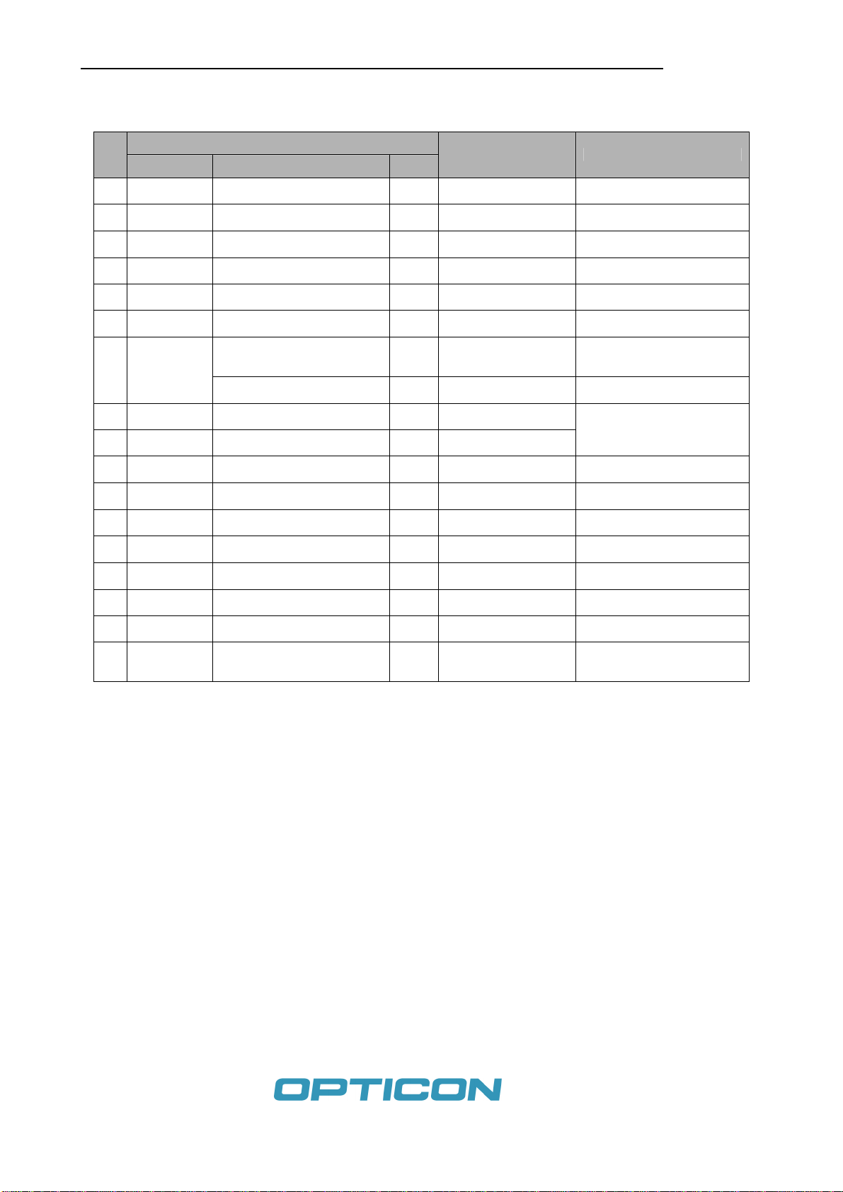
Table 2: CN_1 30-pin Connector Signals for MDI-1000 series
(Opposite pin assignments from the ones of scan engines.)
Signal
No. Name Function I/O Control Notes
1 Reserved Out Not connected
2 Reserved Out Not connected
3 EX_ILLUMn EX LED signal In L: External light ON
H: External light OFF Controls the external light
source.
4 USB_V
CC
5 USB power output Out USB bus power monitor
5 Reserved Out
6 GND System ground
7 USB- In/Out
8 USB+ In/Out USB 1.1
9 GND System ground
10 Reserved In Not connected
11 Reserved Out Not connected
12 Reserved In Not connected
13 V
CC
3.3V-power supply output Out Not connected
14 Reserved Out Not connected
15 GND System ground
16 Reserved Out Not connected
17 GND System ground
18 Reserved In Not connected
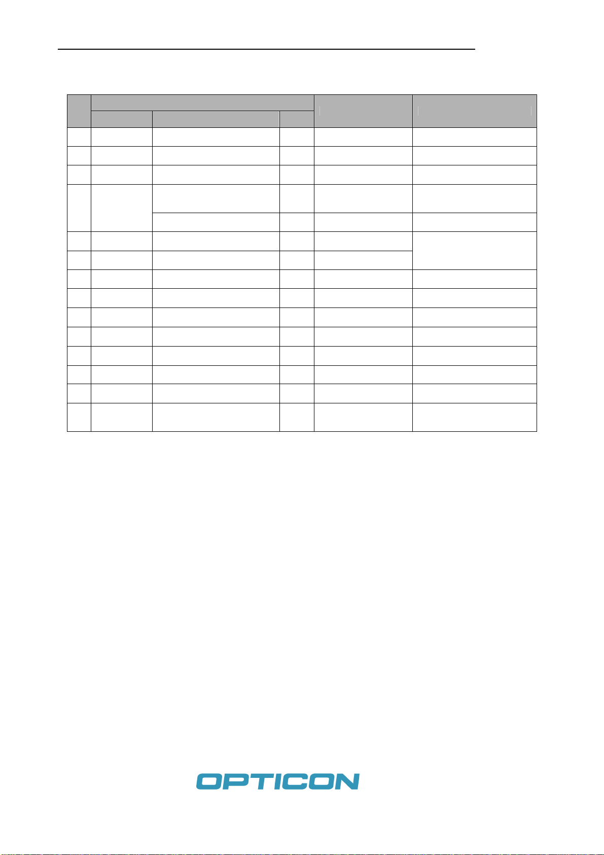
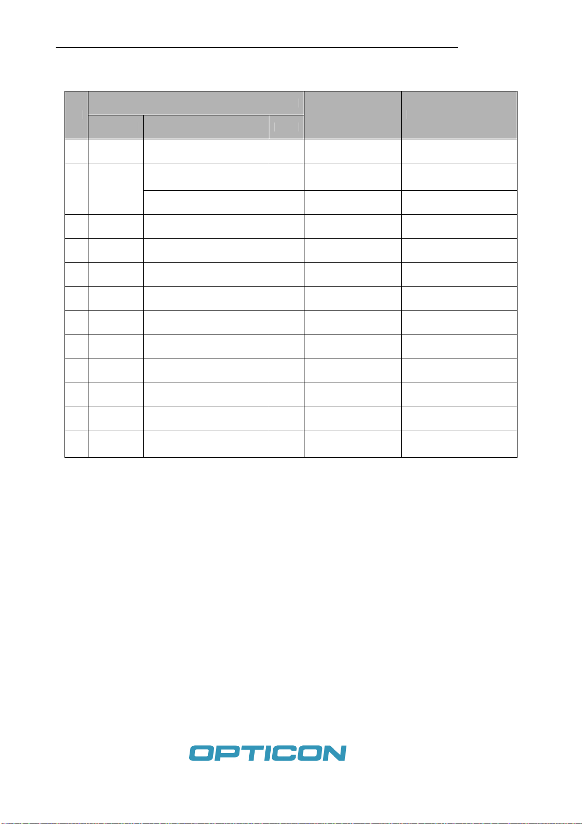
19 TRIGn Start operation signal Out L: Start operation
H: No action Command to start capturing
images or to start decoding
(When in power down mode)
Recovery signal from the power
down state Out L: Recovery from the
power down state
H: No action
20 AIM/WUPn (When not in power down mode)
Aiming control signal Out L: Aiming LED ON
H: Aiming LED OFF
21 GR_LEDn Notifies successful scanning In L: LED ON
H: LED OFF
22 BUZZER Buzzer sounding signal In L: Buzzer OFF
PWM: Buzzer ON PWM signal controls the tone
and the loudness of buzzer
23 POWER
DOWN Notifies power down state of the
scan engine In L: Normal state
H: Power down state
24 RTS Comm. Control signal to the host In Data output request from the
scan engine
25 CTS Comm. Control signal from the
host Out Data output request to the scan
engine
26 TD Data reception signal In Asynchronous data
transmission to the host.
27 RD Data transmission signal Out Asynchronous data
transmission from the host.
28 GND System ground
29 V
CC
3.3V-power supply output Out
30 DWNLDn Maintenance mode control
signal Out L: Maintenance mode
H: Non-operating status
Check the signal upon the
power supply and enable to
re-write on the software.
Note: Signal names are the same with the signal names of MDI scan engines.

MEK-1001 TS07004
3
Table 3: CN_6 17-pin Connector Signals for MDI-23XX series
(Opposite pin assignments from the ones of scan engines.)
Signal
No. Name Function I/O Control Notes
1 EX_ILLUMn EX LED signal In L: External light ON
H: External light OFF Controls the external light
source.
2 GR LEDn Notifies successful scanning In L: LED ON
H: LED OFF
3 BUZZER Buzzer sounding signal In L: Buzzer OFF
PWM: Buzzer ON PWM signal controls the tone
and the loudness of buzzer
4 GND System ground
5 Vcc 3.3V-power supply output Out
6 TRIGn Start operation signal Out L: Start operation
H: No action Command to start capturing
images or to start decoding
(When in power down mode)
Recover signal from the power
down state Out L: Recovery from the
power down state
H: No action
7 AIM/WUPn (When not in power down mode)
Aiming control signal Out L: Aiming LED ON
H: Aiming LED OFF
8 USB- In/Out
9 USB+ In/Out USB 1.1
10 POWERDWN Notifies power down state of the
scan engine In L: Normal state
H: Power down state
11 RTS Comm. Control Signal to the
host In Data output request from the
scan engine
12 CTS Comm. Control signal to the
host In Data output request from the
scan engine
13 TxD Data reception signal In Asynchronous data
transmission to the host
14 RxD Data transmission signal Out Asynchronous data
transmission to the host.
15 GND System ground
16 Vcc 3.3V-power supply output Out
17 DWNLDn Download control signal Out L: Maintenance mode
H: Non-operating status
Check the signal upon the
power supply and enable the
re-write on the software.
Note: Signal names are the same with the signal names of MDI scan engines.

MEK-1001 TS07004
4
Table 4: CN_5 14-pin Connector Signals for MDI-2000 series
(Opposite pin assignments from the ones of scan engines.)
Signal
No. Name Function I/O Control Notes
1 GND System ground
2 Vcc 3.3V-power supply output Out Not connected
3 TRIGn Start operation signal Out L: Start operation
H: No action Command to start capturing
images or to start decoding
(When in power down mode)
Recovery signal from the power
down state Out L: Recovery from the
power down state
H: No action
4 AIM/WUPn (When not in power down mode)
Aiming control signal Out L: Aiming LED ON
H: Aiming LED OFF
5 USB- In/Out
6 USB+ In/Out USB 1.1
7 POWERDWN Notifies power down state of the
scan engine In L: Normal state
H: Power down state
8 RTS Comm. Control signal to the
host In Data output request from the
scan engine
9 CTS Comm. Control signal from the
host Out Data output request to the scan
engine
10 TxD Data reception signal In Asynchronous data
transmission to the host
11 RxD Data transmission signal Out Asynchronous data
transmission from the host.
12 GND System ground
13 V
CC
3.3V-power supply output Out
14 DWNLDn Maintenance mode control
signal Out L: Maintenance mode
H: Non-operating status
Check the signal upon the
power supply and enable to
re-write on the software.
Note: Signal names are the same with the signal names of MDI scan engines.

MEK-1001 TS07004
5
Table 5: CN_2 12-pin Connector Signals for MDL-1000 and MDL-2000 series
(Opposite pin assignments from the ones of scan engines.)
Signal
No. Name Function I/O Control Notes
1 Trigger Start operation signal Out L: Start operation
H: No action
(When in power down mode)
Recovery signal from the power
down state Out L: Recovery from the
power down state
H: No action
2 AIM/WUPn (When not in power down mode)
Aiming control signal Out L: Aiming LED ON
H: Aiming LED OFF There are products which do
not support LED.
3 Decode LED In L: LED ON
H: LED OFF Controlled by the command
4 BUZZER Buzzer sounding signal In L: Buzzer OFF
PWM: Buzzer ON PWM signal controls the tone
and the loudness of buzzer
5 POWER
DOWN Notifies power down state of the
scan engine In L: Normal state
H: Power down state
6 RTS Comm. Control signal to the host In Data output request from the
scan engine
7 CTS Comm. Control signal from the
host Out Data output request to the
scan engine
8 TxD Data reception signal In Asynchronous data
transmission to the host.
9 RxD Data transmission signal Out Asynchronous data
transmission from the host.
10 GND System ground
11 V
CC
3.3V-power supply output Out
12 TEST Maintenance mode control signal Out L: Maintenance mode
H or Open: Normal
Enters into a maintenance
mode when the signal is
turned to L-level.
Note: Signal names are the same with the signal names of MDL scan engines.

MEK-1001 TS07004
6
5. Basic Instructions
5-1. Scanning Operation
Connect the scan engine to the appropriate scan engine connector; CN1,
CN2, CN5 or CN6. Then, connect the host communication; RS-232 or
USB cable to CN3. Connect the power via the AC adaptor.
↓
Turn the Power Switch (POWER) ON.
↓
Press the Trigger Switch (TRIG) and start the scanning operation.
↓
The Good Read (GR) LED illuminates and the BUZZER (BZ) sounds in
cases of successful scans.
Note: The MDI2000 does not have a GRL nor a Buzzer output.
5-2. Aiming and Wake-up Operations
Connect the scan engine to the scan engine connector. Then, connect the
host communication cable to the CN3.
Press Aiming and Wake-up Switch (A_WUP). When the scan engine is in
the power down mode, it recovers from the power down mode. If the scan
engine is in standby mode, the scan engine’s aiming LED illuminates.
Note: There are products which do not support this type of LED
illumination.
5-3. Control from the Host Computer
Universal Menu Interface (MDL/MDL Universal Menu Mode / MDI)
Use the terminal software to output commands and to display the data.
Please refer to a software specification manual of each scan engine for
the details on the command menu.
6. Trouble Shooting
Please confirm the connection of each flex cable and the host communication cable in case
the scan engine does not operate even after turning on the power switch.
Please do not connect a MDL-1000/2000 and a MDI-1000 series scan engines at the same
time. It may damage the device.

MEK-1001 TS07004
7
7.
Detailed View
Figure 1: Detailed View of MEK-1001
1. POWER: Power switch to activate or deactivate the device.
2. TRIG: Trigger switch to start the scanning operation
3. A_WUP: Aiming and wake-up switch
4. D_LD: Maintenance-mode switch to carry out the maintenance of a scan engine.
5. D_LD2: Second maintenance-mode switch
6. BZ1: Buzzer which sounds at the completion of successful scan. For some scan
engines, this buzzer sounds when starting up the scan engine or when
changing the configurations of the scan engine.
7. F1: Fuse (0.63A)
8. U2: RS-232C driver
9. U3: 3.3V DC converter
10. CN1: Connector for MDI-1000 series scan engines (30-pin)
11. CN2: Connector for MDI-2000 series scan engines (12-pin)
12. CN3: 10-pin RS-232C modular jack
13. CN5: Connector for MDI-2300 series scan engines (14-pin)
14. CN6: Connector for MDL-1000 and MDL-2000 series scan engines (17-pin)
15. LED1: (GR) Good Read LED lights in case of a successful scan. (MDL scan
engines do not support this LED.)
16. LED2: (SLEEP) Power down LED
17. LED3: (EX) External illumination LED lights synchronously to the control signal
from the scan engine.
Test Point: Orange colored ellipses

MEK-1001 TS07004
8
Appendix A: Details of the Test Points
No. Signal Name
P2 RTS
P3 CTS
P4 TxD
P5 RxD
P6 Vcc
P7 GND
P8 USB+
P9 USB-
P12 TRIGn
P13 RxD
P14 TxD
P15 CTS
P16 RTS
P17 BUZZER
Appendix B: Mechanical Dimensions of the MEK-1001 Board
Table of contents
Other Opticon Motherboard manuals