OPTILAB PR-30 User manual

OPTILAB
PR-30 EVB USER’S MANUAL
Photo Receiver Evaluation Board
Caution: The user must read this manual before operating the PR EVB.
Operations other than those described in this manual may result in personal
injury and damage to the unit. Ver. 2.1
August 23, 2021

PR EVB User’s Manual ii
Optilab, LLC
600 E. Camelback Road, Phoenix, AZ 85012
Revision History
VERSION
DATE
SUMMARY
1.0
11/01/16
Manual introduced.
2.0
4/28/17
AGC mode incorporated.
2.1
8/23/21
Logo and Format Update
Copyright ©2015 by Optilab, LLC.
All rights reserved.
This document is copyrighted property of Optilab, LLC. It may not be used in whole or in
part for manufacture, sale, or design of items without the written permission of Optilab,
LLC.
Information herein is preliminary and subject to change without any notices.

PR EVB User’s Manual iii
Optilab, LLC
600 E. Camelback Road, Phoenix, AZ 85012
Table of Contents
1. PR-30 Configuration.....................................................................................................................1
1.1 Butterfly Package Pin-out Diagram and Description....................................................1
1.2 Bandwidth Adjustment.............................................................................................................2
1.3 Operation Mode...........................................................................................................................2
2. Evaluation Board...........................................................................................................................3
2.1 Device Mounting Procedure ...................................................................................................3
2.2 Schematic of Evaluation Board..............................................................................................4
2.3 Default Setting..............................................................................................................................5
2.4 Change the Settings....................................................................................................................5
2.4.1 How to use manual gain control (MGC) mode ........................................................5
2.4.2 How to use automatic gain control (AGC) mode....................................................6
2.4.3 How to monitor received signal strength .................................................................6
2.5 Operation Instruction................................................................................................................7

PR EVB User’s Manual 1 of 7
Optilab, LLC
4350 E. Camelback Road, Suite E160, Phoenix, AZ 85018
1. PR-30 Configuration
1.1 Butterfly Package Pin-out Diagram and Description
PR-30 is packaged inside a 14-pin butterfly package. For your reference, we
have included a table of the pin-out diagram for PR-30.
Figure 1 Butterfly Package Pin-out Diagram
Table 1. PR-30 Pin Out Configuration
Pin Configuration
Pin 1
BWH
Bandwidth Coarse Adjust, GND, Floating or Vcc
Pin 2, 5, 7, 8, 12
Vcc
Filtered +3.3 V
Pin 3
GC
Gain Control in MGC mode. VCC, 0-3.3 V analog adjustment.
Set to FLT for AGC mode
Pin 4
OA
Output Amplitude Adjust in AGC mode.
Pin 6
MC
Mode Control. GND= MGC mode, Floating = AGC mode
Pin 9, 11, 13
GND
Ground
Pin 10
RSSI
Received Signal Strength Indicator
Pin 14
BWL
Bandwidth Fine Adjust, GND, Floating or Vcc

PR EVB User’s Manual 2 of 7
Optilab, LLC
600 E. Camelback Road, Phoenix, AZ 85012
1.2 Bandwidth Adjustment
PR-30 offers a bandwidth adjustment feature that allows users to optimize
optical receiver performance for different applications. PR-30 bandwidth can
be adjusted as needed. The table below gives the bandwidth based on BWH
and BWL settings when photo diode is reversed biased at 3.3V.
Table 2. Bandwidth Setting Lookup Table
BWH
BWL
Min. Bandwidth
(GHz)
GND
VCC
13
GND
FLT
15
GND
GND
16
FLT
FLT
18
VCC
GND
20
VCC
FLT
20.5
VCC
VCC
21
In default setting on the evaluation board, both BWH and BWL are preset to
VCC to achieve the largest bandwidth. If a bandwidth smaller than 13 GHz is
desired, the user can lower VPD to further reduce the overall bandwidth of PR-
30.
1.3 Operation Mode
PR-30 integrates a single, differential linear trans-impedance / variable-gain
amplifier (TIA/VGA). The TIA offers two gain control modes: manual gain
control and automatic gain control. In manual mode, MC pin should be
connected to GND. The gain is adjustable from 50 Ω to 5000 Ω differential by
adjusting the GC level. When MC and GC pins are floating, device is operating
in automatic gain control (AGC) mode. In AGC mode, the gain is
automatically adjusted to deliver a constant output voltage. The output
amplitude is adjustable over 20 dB dynamic range by adjusting the level of OA.
Table 3. Operation Mode Selection
Operation Mode
MC Setting (Pin 6)
Amplitude / Gain Adjustment
Manual Gain Control
GND
GC (Pin 3), 0 ~ 3.3V
Auto Gain Control
FLT
OA (Pin 4), 0 ~ 3.3 V
Shut Down
VCC
N.A.
The default setting on the evaluation board is MGC. GC is preset to Vcc to
maximize the TIA gain.

PR EVB User’s Manual 3 of 7
Optilab, LLC
600 E. Camelback Road, Phoenix, AZ 85012
2. Evaluation Board
The Evaluation Board for the PR-30 is used for ease of testing. It provides
convenient access to all 14 pins and the data output ports. Utilizing a zero-
insertion force configuration, the device can be mounted without the need for
soldering as a user-friendly interfacing solution. The EVB is mounted on a
base plate. The base plate can be further mounted to other structures using the
four ¼-20 threaded through holes
2.1 Device Mounting Procedure
i) Place PR-30 onto the evaluation board as show in Fig. 2. Pay attention to its
orientation. The label P and N denotes the positive and negative RF output
ports.
ii) Align pins down into pin chuck. Make sure that they line up and don’t cross
over.
iii) Mount PR to Evaluation board using the four 2-56 screws provided.
iv) Once secured clamp pins down in pin chuck, as shown in Fig. 3.
Figure 2. PR-30 mounting procedure

PR EVB User’s Manual 4 of 7
Optilab, LLC
600 E. Camelback Road, Phoenix, AZ 85012
Figure 3. PR-30 clamped down on the EVB
2.2 Schematic of Evaluation Board
Figure 4. Schematic of Evaluation Board
An external power supply is connected through the power connecting plug.
BWH (JP3) and BWL (JP4) are used to select bandwidth setting. Mode (JP6) is
for operation mode selection. OA (R3) is used AGC mode for constant output
amplitude adjustment. GC (R1) is used manual gain mode for constant gain
setting. Test pins PIN7+/- are used to monitor the reverse bias voltage.

PR EVB User’s Manual 5 of 7
Optilab, LLC
600 E. Camelback Road, Phoenix, AZ 85012
2.3 Default Setting
Figure 5 shows an evaluation board in the default setting. Black jumpers
(included in the shipment) can be used to make connections between two pins
adjacent to each other.
The evaluation board has been preset to MGC mode with the highest
bandwidth setting. Photo diode is reversed biased at Vcc. The TIA gain is
maximized (GC = Vcc).
Figure 5. EVB Default Setting and Controls
2.4 Change the Settings
2.4.1 How to use manual gain control (MGC) mode
To use manual gain control mode, leave evaluation board in its default state,
ensure Mode Pin (JP6) is jumped to pin 2 and 3. Adjust the differential gain by
adjusting the potentiometer GC (R1), clockwise to increase gain.
BWH
BWL
OA
RSSI
Mode
GC

PR EVB User’s Manual 6 of 7
Optilab, LLC
600 E. Camelback Road, Phoenix, AZ 85012
Figure 6. PR-EVB in MGC Mode
2.4.2 How to use automatic gain control (AGC) mode
To use automatic gain control mode, MC and GC pins have to be floating.
First float Mode pin (JP6). Then float GC pin by removing jumper on pin 3.
Adjust potentiometer R3 (OA) to the desired output amplitude, clockwise to
increase amplitude
Figure 7. PR-30 EVB in AGC Mode
2.4.3 How to monitor received signal strength
Received signal strength indicator (RSSI) allows end user to monitor signal
strength by simply probing onto two pin connector labeled RSSI (JP2).
GC ADJUST
MODE
OA ADJUST
JUMPERS
REMOVED

PR EVB User’s Manual 7 of 7
Optilab, LLC
600 E. Camelback Road, Phoenix, AZ 85012
2.5 Operation Instruction
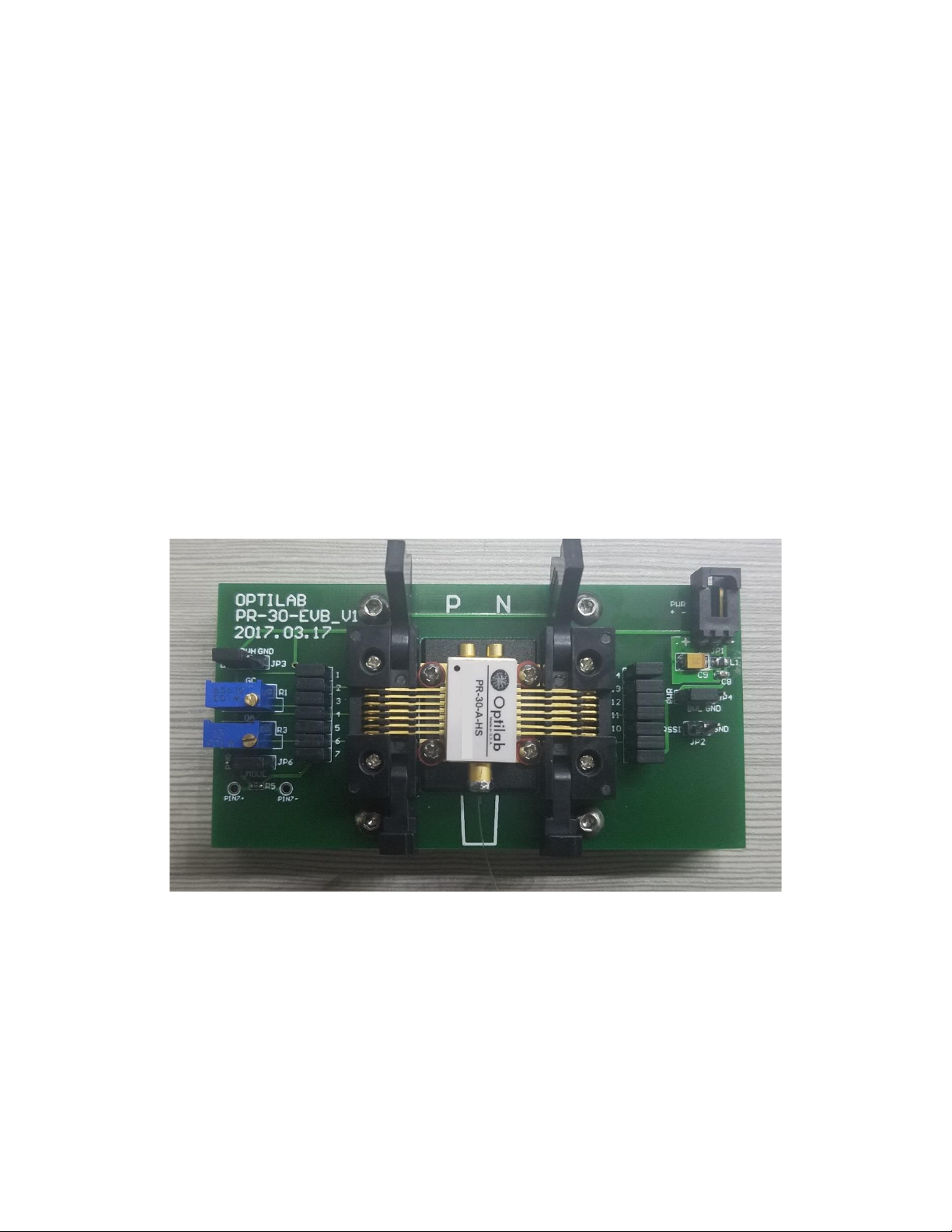
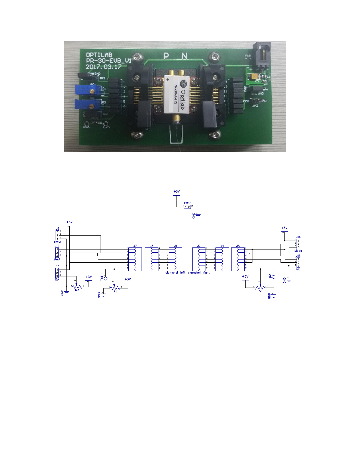
Before powering up device make sure evaluation board is at factory default
setting (see Fig. 5). This is especially important for first time user. Mount the
device firmly as instructed in section 2.1. Use ESD strap during the handling.
Connect both RF output ports to the receiver instrument (e.g., CDR circuit,
oscilloscope etc.) use a pair of RF cables with GPPO (SMPM) connector.
These two RF output ports need AC coupling. Check the specification and
setting of the instrument that the device is going to be connected to. If DC
coupling scheme is used in the corresponding instrument, use external DC
blocks in between. DC coupling causes high current consumption of device
which may damage TIA!!
Connect 2-pin power connector on the right edge of evaluation board to an
external DC power supply. A regulated DC voltage source with low voltage
ripple is recommended. Set the current limit to 93 mA, ramp voltage up to
3.3V. Now device is operating in default setting (MGC mode).
To power off device, ramp DC power supply down until current consumption
is low (typically around 1V) then turn off DC power supply.
Table of contents
Other OPTILAB Motherboard manuals
Popular Motherboard manuals by other brands

AXIOMTEK
AXIOMTEK PICO841 user manual

ASROCK
ASROCK Fatal1ty 990FX Professional user manual

ASROCK
ASROCK R0ME2D16-2T user manual

VIA Technologies
VIA Technologies EPIA-CN10000EG - VIA Motherboard - Mini ITX user manual

Asus
Asus PRIME H510T2-CSM R2.0 manual

Supermicro
Supermicro Supero C9X299-PG300 Quick reference guide