Optimus 12-1978 User manual

Cat. No. 12-1978
OWNER’S MANUAL
Please read before using this equipment.
Stereo 7-Band
4-Channel Equalizer
Under Dash
12-1978.fm Page 1 Tuesday, July 13, 1999 10:31 AM

2
FEATURES
Your Optimus 7-Band 4-Channel
Equalizer is designed to give you ex-
cellent control over the sound pro-
duced by your autosound system.
Unlike standard treble and bass con-
trols, this equalizer lets you adjust the
balance of specific frequency ranges
for a more customized sound. The
special subwoofer crossover switch
gives you a choice of different sub-
woofer output effects.
The equalizer’s features include:
CD Input Jack — lets you easily con-
nect a portable CD player (or any oth-
er portable audio source with a
headphones jack) to the equalizer.
Ultra-Slim Desi
g
n— makes it easy
to mount the equalizer under the dash
or seat.
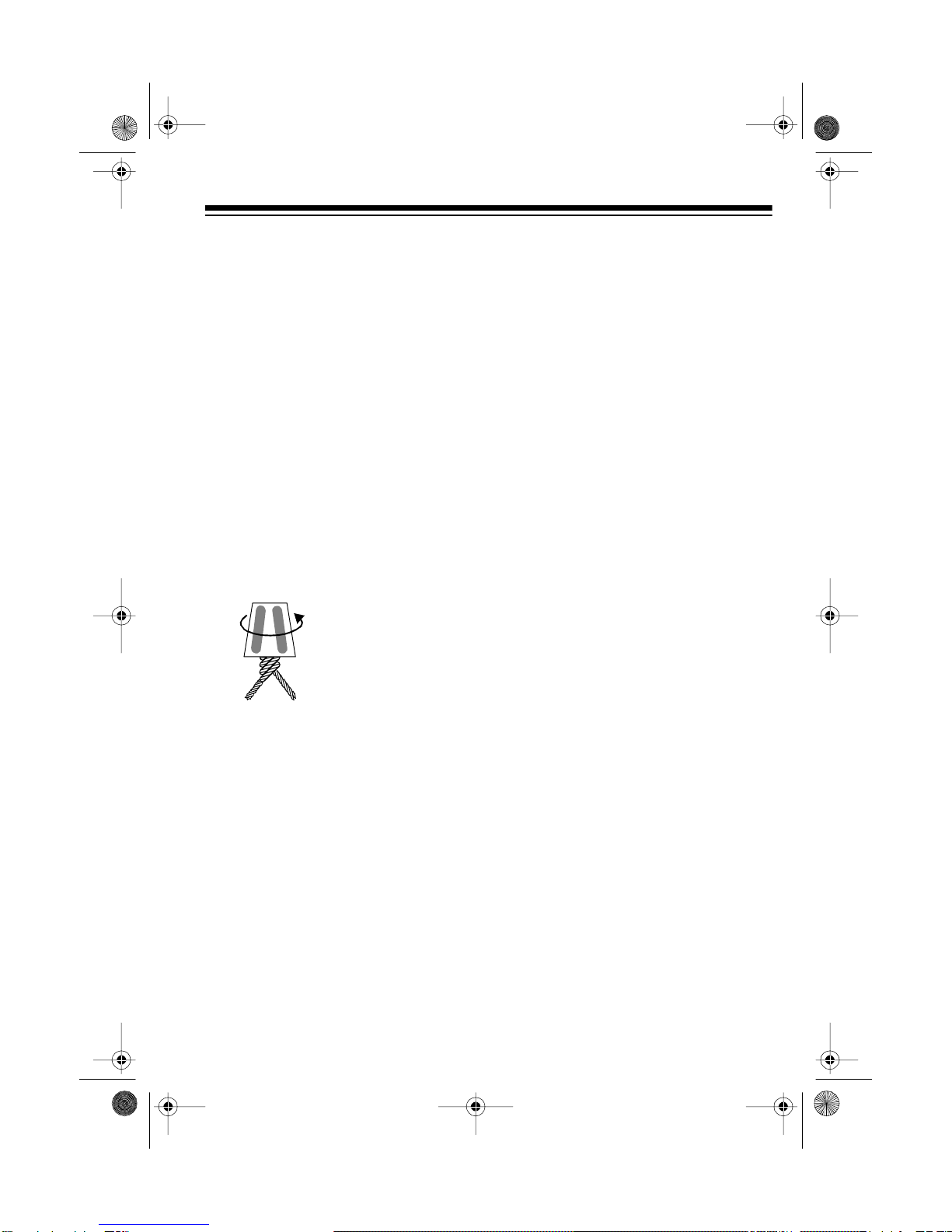
7-Band Equalizer Rotar
y
Controls
— give you control of the basic musi-
cal frequency ranges. The controls
provide an instant visual representa-
tion of the shape you give the sound.
Built-In Fader — lets you easily con-
trol the balance between front and
rear speakers if you have a four-
speaker system.
Two T
y
pes of Inputs — let you use
the equalizer with an autosound sys-
tem that has line-out jacks or that has
only standard speaker outputs.
Three Pairs of Outputs — let you
connect separate stereo amplifiers for
front and rear speakers and a sub-
woofer amplifier for subwoofers.
Built-In Subwoofer Level Control —
lets you easily control the subwoofer
level if you have a subwoofer.
Note: The equalizer does not have a
built-in amplifier. Therefore, if your au-
tosound system does not have both
line-in and line-out jacks for connec-
tion to the equalizer, you must install
front and rear amplifiers. RadioShack
stores sell a wide variety of autosound
amplifiers.
Important: If the connectors on your
vehicle or autosound system are not
compatible with the equalizer’s phono
jacks, contact your local RadioShack
store. RadioShack stores sell adapter
harnesses for many vehicles. Do not
modify the equalizer’s wiring. If you
cut any wire, you cannot obtain a re-
fund or exchange on this product. Ra-
dioShack will provide warranty service
if you cut a wire and find the product is
defective.
© 1996 Tandy Corporation.
All Rights Reserved.
Optimus is a registered trademark used by Tandy Corporation.
RadioShack is a trademark used by Tandy Corporation.
12-1978.fm Page 2 Tuesday, July 13, 1999 10:31 AM

3
CONTENTS
Installation ............................................................................................................ 4
Supplied Hardware ......................................................................................... 4
Choosing a Mounting Location ....................................................................... 4
Installation Guidelines ..................................................................................... 5
Connecting the Input Source .......................................................................... 6
Using the Autosound System’s Line-Out Jacks ........................................ 6
Using the Autosound System’s Speaker Wires ........................................ 7
Connecting Output Amplifiers ......................................................................... 8
Using Your Autosound System’s Amplifier ............................................... 8
Using Separate Amplifiers ........................................................................ 9
Connecting Power ......................................................................................... 10
Testing the Connections ................................................................................ 11
Setting the Subwoofer Crossover Frequency ............................................... 11
Mounting the Equalizer ................................................................................. 12
Connecting a Portable CD Player ................................................................. 13
Operation ............................................................................................................ 15
Turning the Equalizer On and Off ................................................................. 15
Using the Fader Control ................................................................................ 15
Using the Equalizer Controls ........................................................................ 16
Using the Subwoofer Level Control .............................................................. 16
Care and Maintenance ...................................................................................... 17
Replacing a Fuse .......................................................................................... 18
Specifications .................................................................................................... 19
12-1978.fm Page 3 Tuesday, July 13, 1999 10:31 AM

4
INSTALLATION
SUPPLIED HARDWARE
The following items are supplied with the equalizer. Be sure you locate these items
before you throw away the packing materials.
Left Bracket (1)
Right Bracket (1)
Short Machine Screws (4)
Small Flat Washers (7)
Large Lock Washer (1)
Large Flat Washer (1)
Small Lock Washers (7)
Small Sheet Metal Screws (2) Large Sheet Metal Screw (1)
MountingStrap(1)
Long MachineScrew(1)
CHOOSING A
MOUNTING LOCATION
Choose a mounting location that:
• Is as close as possible to your
vehicle’s autosound system
• Does not interfere with the vehi-
cle’s operation
• Is not directly in front of a heating
vent
• Lets you drill mounting holes with-
out damaging other vehicle com-
ponents
12-1978.fm Page 4 Tuesday, July 13, 1999 10:31 AM

5
INSTALLATION
GUIDELINES
To make sure your equalizer works
properly with your autosound system,
install your equalizer in the following
order.
1. Carefully read all the installation
instructions and make a list of the
quantity and length of shielded
audio cables you will need. Your
local RadioShack store carries a
large selection.
Note: Use wire twist connectors
(such as RadioShack Cat. No. 64-
3057) to make wire-to-wire con-
nections.
2. Before you begin installing your
equalizer, disconnect the cable
from the vehicle battery’s negative
(–) terminal. This disconnects
power and helps protect your
vehicle’s electrical system while
you work with the vehicle’s wiring.
Note: After you install the equal-
izer, you must reset your vehicle’s
clock, autosound system’s tuner
memories, and any other clock or
memory devices connected to
your vehicle’s electrical wiring.
3. Connect the input source.
• If your autosound system has
line-out jacks, see “Using the
Autosound System’s Line-Out
Jacks” on Page 6.
Note: This is the preferred con-
nection method.
• If your autosound system does
not have line-out jacks but has
only speaker output wires, see
“Using the Autosound Sys-
tem’s Speaker Wires” on Page
7.
4. Connect the output amplifier by
either:
• Using your autosound system’s
amplifier (see “Using Your Auto-
sound System’s Amplifier” on
Page 8)
• Using separate amplifiers (see
“Using Separate Amplifiers” on
Page 9).
5. Connect power, then test the con-
nections.
6. Set the crossover frequency.
7. Mount the equalizer.
Wire Twist Connector
(Cat. No. 64-3057)
12-1978.fm Page 5 Tuesday, July 13, 1999 10:31 AM

6
CONNECTING THE INPUT SOURCE
Using the Autosound System’s Line-Out Jacks
If your autosound system has line-out jacks, use shielded audio cables with left and
right phono connectors to make these connections.
Note: If your autosound system does not have line-out jacks, see “Using the Auto-
sound System’s Speaker Wires” on Page 7.
1. Connect the phono plugs on one
end of an audio cable to the
equalizer’s L(left) and R(right)
LINE INPUT jacks.
2. Connect the phono plugs on the
other end of the audio cable to
your autosound system’s left and
right line-out jacks.
3. Connect the output amplifiers
using the following guidelines:
• If you are using your autosound
system as the amplifier, see
“Using Your Autosound Sys-
tem’s Amplifier” on Page 8.
• If you are using separate ampli-
fiers, see “Using Separate
Amplifiers” on Page 9.
(illus – Show only the auto-
sound system’s line-out
jacks connected to the equal-
12-1978.fm Page 6 Tuesday, July 13, 1999 10:31 AM

7
Using the Autosound System’s Speaker Wires
If your autosound system has only speaker output wires and does not have line-out
jacks, use wire twist connectors to make these connections.
Note: If your autosound system has line-out jacks, connect your equalizer to them
instead (see “Using the Autosound System’s Line-Out Jacks” on Page 6).
1. Connect the autosound system’s
front left (+) speaker wire to the
equalizer’s white wire.
2. Connect the autosound system’s
front left (–) speaker wire to the
equalizer’s white wire with the
black line.
3. Connect the autosound system’s
front right (+) speaker wire to the
equalizer’s gray wire.
4. Connect the autosound system’s
front right (–) speaker wire to the
equalizer’s gray wire with the
black line.
5. Connect the output amplifiers
using separate amplifiers (see
“Using Separate Amplifiers” on
Page 9).
(illus – Show only the autosound
system’s speaker output wires
connected to the equalizer’s
LINE
12-1978.fm Page 7 Tuesday, July 13, 1999 10:31 AM

8
CONNECTING OUTPUT AMPLIFIERS
Using Your Autosound System’s Amplifier
If your autosound system also has line-in jacks so you can use it as the speaker
amplifier, use shielded audio cables with left and right phono connectors to make
this connection.
Note: To get a higher output power than what your autosound system can produce,
you can connect front, rear, and one or two subwoofers, see “Using Separate Am-
plifiers” on Page 9.
1. Make sure your autosound sys-
tem’s speaker harness is con-
nected to the speakers.
2. Connect the equalizer’s FRONT
(or REAR) L(left) and R(right)
line-out jacks to your autosound
system’s left and right line-in
jacks.
3. Proceed to “Connecting Power”
on Page 10.
(illus – show the autosound sys-
tem’s line-out jacks connected to
the equalizer’s
LINE INPUT
jacks
and
the equalizer’s
FRONT
and
REAR
jacks connected to the autosound
12-1978.fm Page 8 Tuesday, July 13, 1999 10:31 AM

9
Using Separate Amplifiers
Your equalizer has three pairs of line-level phono output jacks that let you connect
it up to three amplifiers (front, rear, and subwoofer). These connections require
shielded audio cables with phono connectors.
Notes:
• The equalizer’s subwoofer out-
puts are mono. If you use only
one subwoofer, connect it to either
of the equalizer’s SUB output
jacks.
• If you are using your autosound
system as the amplifier, see
“Using Your Autosound System’s
Amplifier” on Page 8.
1. Connect the equalizer’s L(left)
and
R(right) FRONT jacks to the
front amplifier’s left and right line-
in jacks.
2. Connect the equalizer’s L(left)
and R(right) REAR jacks to the
rear amplifier’s left and right line-
in jacks.
3. Connect the equalizer’s L(left)
and
R(right) SUB jacks to the sub-
woofer amplifier’s left and right
line-in jacks.
4. Refer to the amplifiers’ owner’s
manuals to connect the front, rear,
and subwoofer speakers.
5. Proceed to “Connecting Power”
on Page 10.
(illus – show the autosound system’s line-
out jacks connected to the equalizer’s
LINE
INPUT
jacks
and
the equalizer’s
FRONT
,
REAR
, and
SUB
jacks connected to three
12-1978.fm Page 9 Tuesday, July 13, 1999 10:31 AM

10
CONNECTING POWER
1. Connect the equalizer’s red (+)
POWER LEAD wire with the in-line
fuse holder labeled FUSE 1A to a
terminal in your vehicle’s fuse
block that turns on and off with the
ignition.
Note: To avoid a “pop” sound
when you turn off the equalizer,
you can connect the equalizer’s
red power wire to the autosound
system’s switched power lead.
2. Connect the equalizer’s black
GROUND wire to a chassis ground
such as a clean, metal bolt
attached to the vehicle’s frame.
Be sure the bolt is not insulated
from the frame by a plastic part.
3. Connect the equalizer’s blue
500MA/MAX wire to all the output
amplifiers’ (front, rear, and sub-
woofer) switched power leads.
Note: This wire does not provide
power to the amplifiers. It simply
turns them on and off with the
equalizer. The amplifiers must be
designed for use with a switched
power lead. If you do not use this
wire, secure it with a wire tie so it
does not touch any metal object.
4. Reconnect the cable to the vehi-
cle battery’s negative (–) terminal.
5. Proceed to “Testing the Connec-
tions” on Page 11.
(illus – show the equalizer’s power, remote,
and ground wires with labels to the appropri-
ate sources, and show audio cables connect-
ed to all the equalizer’s input and output jacks
with labels to the appropriate destinations or
12-1978.fm Page 10 Tuesday, July 13, 1999 10:31 AM

11
TESTING THE
CONNECTIONS
Turn on your vehicle’s ignition, then
follow Steps 1-4 of “Operation” on
Page 15 to test the equalizer.
If the equalizer works properly, pro-
ceed to “Setting the Subwoofer Cross-
over Frequency.”
If the equalizer does not work proper-
ly, immediately turn off your vehicle’s
ignition and the equalizer, disconnect
the cable to your vehicle battery’s
negative (–) terminal, and recheck all
connections.
SETTING THE
SUBWOOFER
CROSSOVER
FREQUENCY
The task of the crossover selector is to
direct a selectable range of audio fre-
quencies to the subwoofer speaker.
You can select one of three frequency
crossover points, 80, 120, or 160 Hz.
All signals at or below the selected fre-
quency “cross over” to your subwoofer
speaker.
Before you mount the equalizer, you
need to set the 80/120/160 crossover
switch on the back of the equalizer.
To select the subwoofer crossover fre-
quency which suits your vehicle’s
sound system and acoustics and your
listening preference, play a selected
recording or radio station in your auto-
sound system, then simply set 80/120/
160 Hz to whichever setting sounds
best.
• A lower number decreases the
range of low-frequency sounds.
• A higher number increases the
range of low-frequency sounds.
Note: If the bass is “boomy” you
may be overdriving the subwoofer
speaker. To correct this, either
reduce the volume or set 80/120/
160 Hz to a lower frequency set-
ting.
Proceed to “Mounting the Equalizer”
on Page 12.
(il-
12-1978.fm Page 11 Tuesday, July 13, 1999 10:31 AM

12
MOUNTING THE EQUALIZER
After you complete all the connections and test the equalizer, follow these steps to
mount the equalizer.
1. Disconnect the cable from the
vehicle battery’s negative (–) ter-
minal and disconnect the equal-
izer from your autosound system
and from any amplifier(s).
2. Using the supplied machine
screws, temporarily attach the
mounting brackets to the equal-
izer and position both in the
selected mounting location.
3. Mark the positions for the mount-
ing brackets on the mounting sur-
face by tracing the outside edges
of the brackets.
4. Remove the mounting brackets
from the equalizer, position the
brackets as marked on the mount-
ing surface, then trace the loca-
tions of the mounting holes.
5. Drill 3/16-inch diameter holes in
each of the marked locations.
Caution: Be sure you do not drill
into or damage anything behind
the mounting surface.
6. Using the small sheet-metal
screws and washers, attach the
mounting brackets to the mount-
ing surface.
(il-
12-1978.fm Page 12 Tuesday, July 13, 1999 10:31 AM

13
7. Using the supplied machine screw
and washers, attach the metal
strap to the back of the equalizer.
8. Using either an existing bolt on
your vehicle or a supplied large
sheet metal screw, attach the
strap’s other end to a solid metal
part of the vehicle. This strap
ensures proper electrical ground-
ing and helps secure the equal-
izer.
9. Using the supplied machine
screws and small washers, attach
the equalizer to the mounting
brackets.
10. Reconnect the equalizer to your
autosound system and, if neces-
sary, to the amplifier(s).
11. Reconnect the cable to the vehi-
cle battery’s negative (–) terminal.
CONNECTING A
PORTABLE CD PLAYER
You can connect the headphone out-
put of a portable CD player to the
equalizer’s front panel so you can lis-
ten to it through your autosound sys-
tem.
You need a patch cord with a 1/8-inch
stereo plug at one end and a stereo
plug that fits the CD player’s head-
phone jack at the other end. Patch
cords are available at your local Ra-
dioShack store.
1. Set the CD player’s and your
autosound system’s volume con-
trols to their lowest settings.
2. Turn off the equalizer and the CD
player.
3. Connect the patch cord between
the CD player’s headphone jack
and the CD jack on the front of the
equalizer.
Note: This disconnects the equal-
izer’s audio input from the auto-
sound system.
4. Turn on the equalizer and the CD
player, and start the CD player.
12-1978.fm Page 13 Tuesday, July 13, 1999 10:31 AM

14
5. If you connected the equalizer’s
output to your autosound system’s
line-in jacks, set the CD player’s
volume control to the highest set-
ting and adjust your autosound
system’s volume as desired.
If you connected the equalizer’s
output to separate amplifiers,
adjust the CD player’s volume as
desired.
6. Adjust the equalizer’s frequency
controls.
To listen to the autosound system,
disconnect the patch cord from the
equalizer.
12-1978.fm Page 14 Tuesday, July 13, 1999 10:31 AM

15
OPERATION
TURNING THE
EQUALIZER ON AND
OFF
1. Set the autosound system’s vol-
ume to its lowest setting.
2. Turn on the vehicle’s ignition and
the autosound system.
3. Press POWER on the equalizer.
The lights around each rotary con-
trol button turns on.
4. Adjust the autosound system’s
volume.
To turn off the equalizer, press POW-
ER so the POWER indicator turns off.
USING THE FADER
CONTROL
Rotate FADER to adjust the balance
between front and rear speakers.
Rotating FADER to F(front) increases
the sound level of the front speakers
and decreases the sound level of the
rear speakers.
Rotating FADER to R(rear) increases
the sound level of the rear speakers
and decreases the sound level of the
front speakers.
(il-
(il-
12-1978.fm Page 15 Tuesday, July 13, 1999 10:31 AM

16
USING THE EQUALIZER
CONTROLS
Set the autosound system’s treble and
bass controls (or tone control) to the
center position. Then adjust the equal-
izer’s controls for the desired sound.
Each rotary control affects a range of
frequencies. The midpoint of each ro-
tary control is indented so you can
easily set the control to the center po-
sition.
Setting a control to the midpoint
leaves a frequency range’s level un-
changed (flat response).
To boost a frequency range’s level,
turn the control clockwise toward +. To
lower the level, turn the control coun-
terclockwise toward –.
USING THE
SUBWOOFER LEVEL
CONTROL
Turning this control toward + increas-
es the subwoofer’s volume level.
Turning this control toward – reduces
the subwoofer’s volume level.
(il-
(il-
12-1978.fm Page 16 Tuesday, July 13, 1999 10:31 AM

17
CARE AND MAINTENANCE
Your Optimus 7-Band Rotary Control Passive 4-Channel Equalizer with Subwoofer
Crossover is an example of superior design and craftsmanship. The following sug-
gestions will help you care for your equalizer so you can enjoy it for years.
Keep the equalizer dry. If it gets wet, wipe it dry immediately. Liq-
uids might contain minerals that can corrode the electronic circuits.
Use and store the equalizer only in normal temperature environ-
ments. Temperature extremes can shorten the life of electronic de-
vices, and distort or melt plastic parts.
Handle the equalizer gently and carefully. Dropping it can damage
the circuit boards and can cause it to work improperly.
Keep the equalizer away from dust and dirt, which can cause pre-
mature wear of parts.
Wipe the equalizer with a damp cloth occasionally to keep it look-
ing new. Do not use harsh chemicals, cleaning solvents, or strong
detergents to clean it.
Modifying or tampering with the equalizer’s internal components can cause a mal-
function and might invalidate its warranty. If your equalizer is not performing as it
should, take it to your local RadioShack store for assistance.
CLEANER
12-1978.fm Page 17 Tuesday, July 13, 1999 10:31 AM

18
REPLACING A FUSE
• If the autosound system does not
operate, check the fuse in the
autosound system’s power wire.
• If the equalizer does not operate,
check the fuse in the equalizer’s
power wire.
• If neither operates and both fuses
are good, check your vehicle’s
fuses.
Follow these steps to check and
change the equalizer’s fuse in the
power wire between the equalizer and
the fuse block.
Warning: Before you replace a fuse,
turn off the vehicle’s ignition, the auto-
sound system, the equalizer, and the
amplifiers.
1. Disconnect the equalizer’s red (+)
power lead wire from the fuse
block.
2. Push the fuse holder’s two parts
together and twist so they spring
apart.
3. If the fuse is blown, replace it with
a standard 11/4¥ 1/4inch, 1 amp,
fast-acting fuse (such as Cat. No.
270-1005, not supplied).
Caution: Do not use a fuse with a
rating greater than 1 amp or dam-
age to your equalizer could result.
4. Reassemble the fuse holder by
pushing together and twisting the
two parts so they snap together.
5. Reconnect the appropriate power
wire.
Note: If the fuse immediately blows
again, check for pinched wires. Also,
be sure you correctly completed all
connections and installed a fuse with
the proper ratings.
(il-
12-1978.fm Page 18 Tuesday, July 13, 1999 10:31 AM

19
SPECIFICATIONS
Center Frequencies.............60 Hz, 150 Hz, 400 Hz, 1 kHz, 2.4 kHz, 6 kHz, 15 kHz
Frequency Response ...........................................20–20,000 Hz (at ±3 dB, 400 mV)
Input Level, Front/Rear (for 400 mV Output)
High Impedance......................................................................................400 mV
CD ...........................................................................................................400 mV
Low Impedance...........................................................................................2.5 V
Input Level, Subwoofer (for 400 mV Output)
High Impedance......................................................................................200 mV
CD...........................................................................................................200 mV
Low Impedance.........................................................................................1.25 V
Total Harmonic Distortion ..................................Less than 0.1% (at 400 mV Output)
Output Impedance......................................................................................1.2 kOhm
Signal-to-Noise Ratio........................................................................................85 dB
Separation........................................................................................................60 dB
Control Range ................................................................................................±12 dB
Subwoofer Cut Off Frequencies (at –3 dB, 12 dB/Oct) .........80 Hz, 120 Hz, 160 Hz
Current Drain................................................................................100 mA Maximum
Power Supply Voltage .................................................DC, 12-Volt Negative Ground
Dimensions (HWD)..................................1 ¥ 67/8¥ 61/4inches, (2.5 ¥ 17.5 ¥ 16 cm)
Weight ............................................................................................1 lb, 5 oz (600 g)
12-1978.fm Page 19 Tuesday, July 13, 1999 10:31 AM

RadioShack
A Division of Tandy Corporation
Fort Worth, Texas 76102
4A6 Printed in China
RadioShack Limited Warranty
This product is warranted against defects for 1 year from date of purchase from
RadioShack company-owned stores and authorized RadioShack franchisees and deal-
ers. Within this period, we will repair it without charge for parts and labor. Simply bring
your RadioShack sales slip as proof of purchase date to any RadioShack store. War-
ranty does not cover transportation costs. Nor does it cover a product subjected to mis-
use, accidental damage, alteration or improper installation.
EXCEPT AS PROVIDED HEREIN, RadioShack MAKES NO EXPRESS WARRANTIES
AND ANY IMPLIED WARRANTIES ARE LIMITED IN DURATION TO THE DURATION
OF THE WRITTEN LIMITED WARRANTIES CONTAINED HEREIN. Some states do
not permit limitation or exclusion of implied warranties; therefore, the aforesaid limita-
tion(s) or exclusion(s) may not apply to the purchaser.
This warranty gives you specific legal rights and you may also have other rights which vary from
state to state.
We Service What We Sell
10/95
12-1978.fm Page 20 Tuesday, July 13, 1999 10:31 AM
Table of contents
Popular Stereo Equalizer manuals by other brands

ARC Audio
ARC Audio DXE Manual and user guide

Coyote Point Systems
Coyote Point Systems Equalizer Installation and administration guide

Behringer
Behringer Ultragrph Digital DEQ1024 user guide

Deer Creek Audio
Deer Creek Audio EQ901 B Series user guide

LA Audio Electronic
LA Audio Electronic EQX20 Specification sheet

Technical Pro
Technical Pro EQ7153 user manual