Condential 1-1
EX612/EX615/EW615i/EX612i/EX615iEX615i
Chapter 1
Introduction
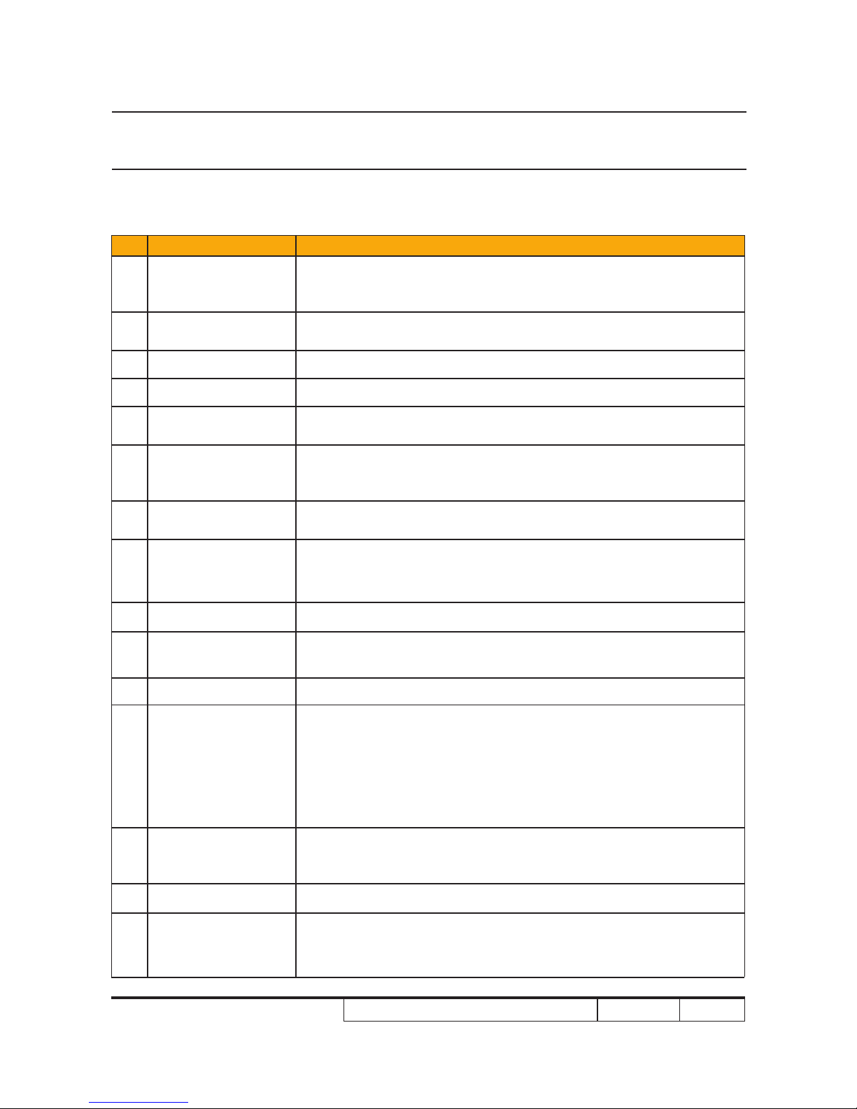
No Item Description
1Technology
● 0.55” XGA 2xLVDS SERIES 450 DMD DC3 (For EX615/EX612/
EX612i/EX615i)
● 0.65” WXGA 2xLVDS SERIES 450 DMD DC3(For EW615i) 0.65” WXGA 2xLVDS SERIES 450 DMD DC3(For EW615i)
2Dimension
(W x D x H) ● 324 x 234 x 97 mm
3 Weight ● 6.3-6.4 lbs
4 Power Supply ● Auto-ranging: 100V~ 240V ± 10%, 50~ 60Hz
5Keystone
Correction ● �/-40 degree (TI spec.)�/-40 degree (TI spec.)
6Resolution
● Native Resolution: 1024 x 768(For EX615/EX612/EX612i/EX612i/
EX615i))
● Native Resolution: 1280 x 800(For EW615i)
7 Power consumption ● Full Mode:(Typ)298W,(Max)328W @ac 110V
● ECO Mode:(Typ)247W,(Max)272W @ac 110V
8 Throw ratio
● 1.95 ~ 2.15 @60”(For EX615/EX612/EX612i)
● 1.28~1.536:1 @60” (For EW615i)1.28~1.536:1 @60” (For EW615i)(For EW615i)
● 1.6~1.92(D/W) @ 60” (For EX615i)1.6~1.92(D/W) @ 60” (For EX615i)(For EX615i) EX615i)EX615i)
9 Projection lens ● YM09X/FPL30, F# 2.41~ 2.55 @60”, f= 21.8 ~ 24 mm @60”
10 Lamp life ● 2500 Hours, 50% Survival Rate (Standard-Mode)
● 4000 Hours, 50% Survival Rate (ECO-Mode)
11 Offset ● 115% ± 5%
12 Video compatibility
● NTSC: NTSC M 3.58 MHz, 4.43 MHz
● PAL: PAL B/D/G/H/I/M/N, 4.43 MHz
● SECAM: SECAM B/D/G/K/K1/L, 4.25/4.4 MHz
● Component: 480i/p, 576i/p, 720p (50/60Hz), 1080i/p (50/60Hz)
● HDTV: 720p(50/60Hz), 1080i(50/60Hz),1080P(24/50/60Hz) (ForHDTV: 720p(50/60Hz), 1080i(50/60Hz),1080P(24/50/60Hz) (For
EW615i/EX615i)/EX615i))
13 Aspect ratio
● 4:3, 16:9 I, 16:9 II, NATIVE, AUTO (For EX615/EX612/EX612i/X615/EX612/EX612i/
EX615i ))
● 4:3, 16:9 or 16:10, LBX, Native, Auto(For EW615i)
14 Lamp ● 230 W OSRAM Lamp E20.8 elliptic
15 Color Wheel
● 5 Segments; RGBYW; Filter Diameter 40 mm
● R76Y32G78W98B76
● 2x,7200 RPM
1-1 Highlight