Orbis COMFORTVIEW User manual

ORBIS COMFORTVIEW ORBIS CALORAMA
ORBIS DIRECT VENT ROOM
HEATERS
Complete instructions for safe installation, operation and servicing of units
manufactured for use with natural gas and propane liquefied petroleum gases.
CALORAMA/COMFORT VIEW SERIES DIRECT VENT
WALL FURNACE
INSTALLATION AND OPERATING MANUAL
OWNER’S MANUAL
P/N CCV - MANUAL
CAUTION: Read these printed instructions
prior to starting the installation of this unit
ATTENTION:Heaters installed in the State
of Massachusetts must be installed by a
licensed plumber or gas fitter.
IMPORTED BY:
The Gas Appliance Company, Inc.
FLORIDA, US of A
www.orbisheat.com
WARNING: If the information in this manual
is not followed exactly, a fire or explosion
may result causing property damage,
personal injury or loss of life.
- Do not store or use gasoline or other flammable
vapors and liquids in the vicinity of this or any
other appliance.
- WHAT TO DO IF YOU SMELL GAS
-Do not try to light any appliance.
-Do not touch any electrical switch; do not use
any phone in your building.
-Immediately call your gas supplier from a
neighbor’s phone. Follow the gas supplier’s
instructions.
-If you cannot reach your gas supplier, call the
fire department.
- Installation and service must be performed by
a qualified installer, service agency or the gas
supplier.

1
CALORAMA/COMFORT VIEW SERIES DIRECT VENT WALL FURNACE
INSTALLATION AND OPERATING MANUAL
SECTION I - Introduction and Safety Information
Introduction
Basic Description
Qualified Service Agency
Safety Rules
Safety Information for Users of Propane / L.P. Gas
Propane / L.P. Gas odor Warning
CALORAMA/COMFORT VIEW (CCV) HEATER SPECIFICATIONS
SECTION II – Installing Your Orbis ( CCV ) Direct Vent Space Heater
Unpack the Heater
Locating the Orbis Calorama/Comfort View Series Space Heaters
Figure 1: Outside Clearances to the Vent Cap
Figure 2: Clearances for Mounting the Heater Itself
Table 2: Minimum Clearances Required for Mounting
Mounting Template
Figure 3: ALL MODELS – Unit Mounting Instructions
Figure 4: Unit Mounting Template Position
Figure 5: Wall Mounting Plate
SECTION III - Vent, Wall Plate and Unit Installation
Unpack the Vent Assembly
Prepare for Installation
Figure 6:Exploded Side View of Vent Installation
Vent and Wall Plate Installation
Figure 7: Vent Kit Assembly
Figure 8:Vent Cap as seen from the Outside
Connect Gas Piping
Gas Supply
Pressure Testing of the Gas Supply Piping System
Figure 9: Guidelines for Gas Piping Connections
Check for Gas Leaks
Installing the Unit Cover
Lighting the Unit
Figure 10:Lighting Instructions
Adjusting the Thermostat
SECTION IV - Maintenance Instructions
Maintenance Instructions (General)
Maintenance Instructions for Calorama/Comfort View Series Heaters
Figure 11:Flame Pattern Calorama/Comfort View Series
SECTION V - Troubleshooting Guide
SECTION VI - Replacement Parts Guide
SECTION VII - Limited Warranty
SECTION VIII - Blower Option
INDEX
Page 2
Page 2
Page 2
Page 3
Page 4
Page 5
Page 5
Page 6
Page 6
Page 7
Page 8
Page 8
Page 8
Page 9
Page 10
Page 10
Page 11
Page 11
Page 11
Page 12
Page 13
Page 13
Page 14
Page 14
Page 14
Page 15
Page 15
Page 16
Page 16
Page 16
Page 17
Page 18
Pages 18-20
Page 20
Pages 21-23
Pages 24-25
Pages 26-27
Pages 28-29

2
SECTION I
INTRODUCTION AND SAFETY INFORMATION
INTRODUCTION:
Your purchase of the ORBIS Calorama/Comfort View I, II or III gas fired direct vent wall
furnace will reward you with many years of satisfying safe operation. Read these
instructions carefully. If you cannot understand them, or donot feel comfortable
installing this unit, contact a qualified service technician or your gas supplier for assistance.
BASIC DESCRIPTION:
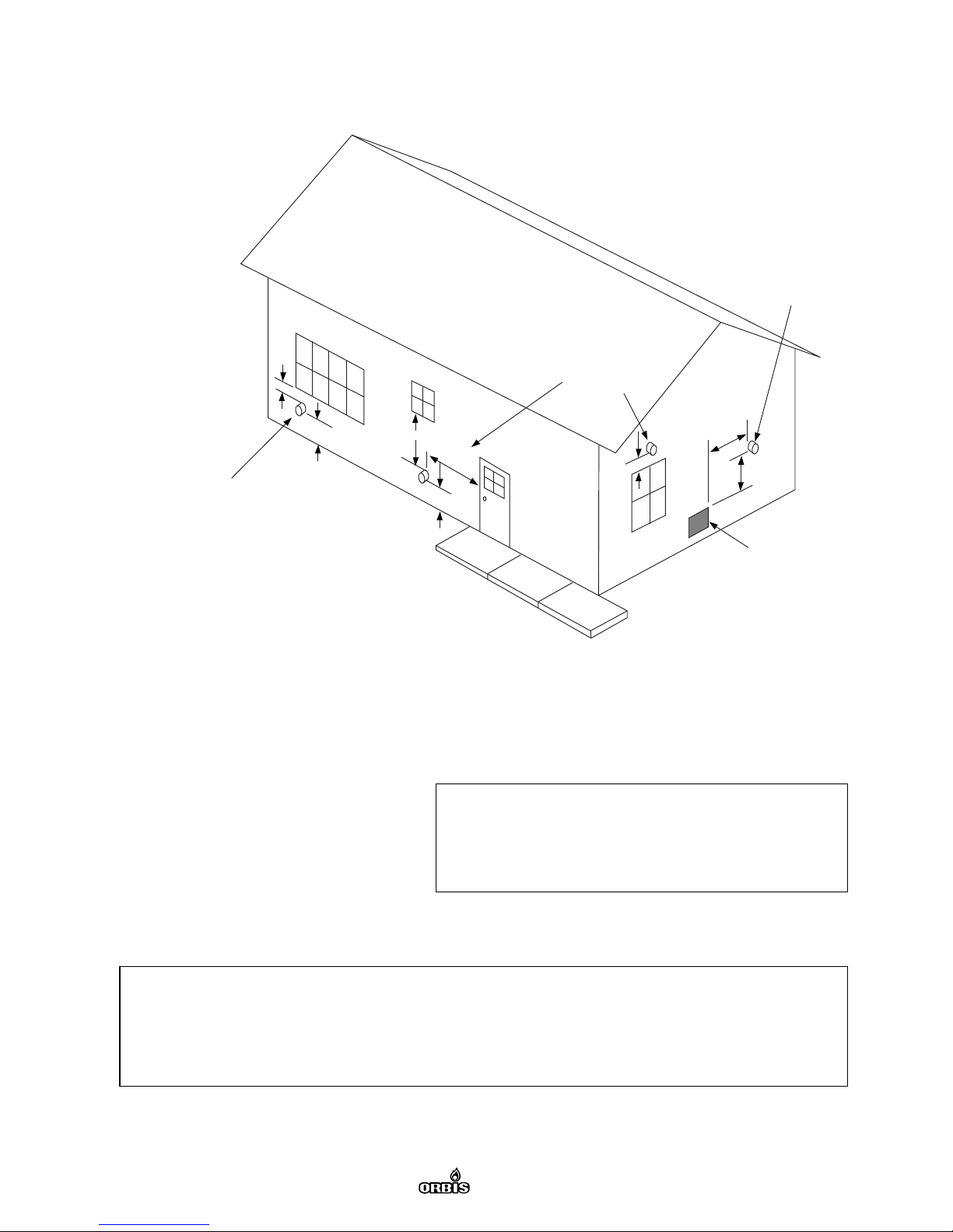
Your direct vent wall furnace is shipped ready to install against an exterior wall up to
12" thick. For walls less than 12", the vent kit must be trimmed.
QUALIFIED SERVICE AGENCY:
A qualified service agency is defined as any individual, firm, corporation or company
which either in person or through representatives, is engaged in and is responsible for:
(1) the installation or replacement of gas piping or (2) the connection, installation, repair
or servicing of equipment, who is experienced in such work, familiar with all precautions
required, and has complied with all requirements of the authority/authorities having
jurisdiction.
WARNING:
This unit is certified to ANSI Z21.86 (Most Recent Edition) Direct Vent Wall Furnace
Standard (CAN 2-32M98) to provide safe, trouble free operation throughout the
expected life of the unit. Any alteration, modification or adjustment not specifically
mentioned in this owner’s manual is NOT authorized by the manufacturer, distributor or
certifying agency, and may result in the unsafe operation ofthis unit. Responsibility for
these modifications rests solely with the individual or company who performed the change.
This unit must be installed in strict accordance with these instructions and all applicable
local codes, if any. In the absence of local codes, refer to these instructions and National
Fuel Gas Code, ANSI Z 223.1/Canadian Installation Code, CAN/CGA B149, and Combination
Control Standards ANSI Z21.78, most current edition. This unit has been tested IAW
(NFPA #54. These publications are available from the American National Standards
Institute, 1430 Broadway, New York, NY 10018, or from the National Fire Protection
Association, Batterymarch Park, Quincy, Mass., 02269. In Canada, refer to
CAN/CGA-B149.1 (.2), Canadian Standards, most recent edition.
GENERAL SAFETY RULES
WARNING: READ THESE RULES AND THE INSTRUCTIONS CAREFULLY. FAILURE TO FOLLOW
THESE RULES AND INSTRUCTIONS COULD CAUSE A MALFUNCTION OF THE FURNACE.
THIS COULD RESULT IN DEATH, SERIOUS BODILY INJURY, AND/OR PROPERTY DAMAGE.

3
SAFETY RULES:
1) USE ONLY MANUFACTURER’S REPLACEMENT PARTS. Use of anyother parts could
cause injury or death.
2) Only specially modified and marked units are for use in a travel trailer, recreational
vehicle or mobile home. A primary temperature limit control to limit the outlet air
temperature is provided with each optional Mobile / Manufactured Home Installation
Kit for installations in a travel trailer, recreational vehicle or mobile home.
3) MAINTAIN all clearances specified in the section entitled "Locating the
Orbis Calorama/ Comfort View Series Heater." (See Fig. 1 and 2 and Table 2)
4) THIS APPLIANCE IS ONLY FOR USE WITH THE TYPE OF GAS INDICATED ON THE
RATING PLATE. Be sure furnace is for type of gas to be supplied. Check the rating plate in
the inside of the heater. Do not change the furnace to use other gases. Unsafe operation
could result and could cause bodily injury and death.
5) Any safety screen, guard or parts removed for servicing the appliance must be
replaced prior to operating the appliance to avoid property damage, bodily injury or death.
6) INSTALL the furnace to vent directly to the outdoors using only the vent assembly
supplied with the unit, so that harmful gases will not gather inside of the building.
(The vent kit part number for your unit can be found in the exploded parts view at the
end of this manual)
7) NEVER vent flue gases into another room, a fireplace or any space inside a building.
8) NEVER test for gas leaks with an open flame.
9) ALLOW furnace to cool before servicing.
10) Children and adults should be alerted to the hazards of high, top output, surface
temperatures and should stay away to avoid burns or possible clothing ignition.
11) Young children should be carefully supervised when theyare in the same room as
the furnace.
12)Clothing or other flammable material should not be placed on or near the appliance.
13) Do not lay any object on top of the heater that could obstruct the louvers of the unit
through which warm circulating air needs to pass. DON’T allow children to insert articles
in the louvers on the heater.
14) INSTALLATION AND REPAIR SHOULD BE DONE BY A QUALIFIED SERVICE PERSON.
The appliance should be inspected before first use and at least annually by a qualified
service person. More frequent cleaning may be required due to excessive lint from
carpeting, bedding material, etc. It is imperative that control compartments, burners and
circulating air passageways of the appliance be kept clean.

4
SAFETY INFORMATION FOR USERS OF PROPANE / L.P. GAS:
Propane/L.P. gas is highly flammable gas that can cause fireand explosions. Propane/L.P.
gas is naturally odorless, but a special odorant is added to the gas to alert you to the
presence of a gas leak, should one occur. This odor may fadeover time. It is recommended
that you obtain a "Scratch and Sniff" brochure to familiarize occupants with the odor
associated with propane/LP gas. Not everyone is familiar with the safety precautions
covering the use of Propane/L.P. gas. These precautions willhelp you safeguard your
family and your property from an accident. Read the following carefully and make sure
that everyone in your household knows the correct action to take in the event of a leak
in the Propane/L.P. gas system.
PROPANE / L.P. GAS ODOR WARNING
The odorant put into the Propane/L.P. gas by your gas supplier will allow you to detect
the distinctive smell of gas in the event of a leak. If you smell propane / L.P gas anywhere
in or around your house or apartment, this odor indicates it is time to take immediate
action in order to reduce or eliminate the risk of injury and or property damage.
KNOW AND MAKE SURE OTHERS IN YOUR HOUSEHOLD KNOW THE FOLLOWING
PROCEDURES TO TAKE IN THE EVENT OF A PROPANE / L.P. GAS LEAK:
1. DO NOT operate electric switches, light matches, or use your telephone. Do not do
anything that could create an open flame or sparks, resulting in the ignition of leaking gas.
2. USE a neighbor’s telephone and call a qualified Propane / L.P. gas service technician
or the gas supplier AND the fire department. Even if the odor of Propane / L.P. gas fades
and you cannot detect the smell of gas, DO NOT turn on any appliances.
3. DO NOT re-enter the building or area until it has been declared safe to enter by the
fire department or other authority. A properly trained and qualified Propane / L.P. gas
service technician or gas supplier must repair the system leak and then re-light your gas
appliances for you.
WARNING: DO NOT USE THIS HEATER IF ANY PART HAS BEEN UNDERWATER.
IMMEDIATELY CALL A QUALIFIED SERVICE TECHNICIAN TO INSPECT THE APPLIANCE
AND TO REPLACE ANY PART OF THE CONTROL SYSTEM
AND ANY GAS CONTROL WHICH HAS BEEN UNDER WATER.
IF YOU DO NOT UNDERSTAND THIS INFORMATION OR FEEL YOU NEED
ADDITIONAL INFORMATION, CONTACT YOUR GAS SUPPLIER.

5
CALORAMA/COMFORT VIEW (CCV) SERIES HEATER SPECIFICATIONS
Model
Maximum input BTU/h (KW)
Minimum input BTU/h (KW)
NATURAL GAS
Manifold Gas Pressure:
Minimum Gas Supply Pressure
Maximum Gas Supply Pressure
PROPANE/LP GAS *
Manifold Gas Pressure:
Minimum Gas Supply Pressure
Maximum Gas Supply Pressure
Gas Inlet Connection
Minimum Wall Thickness
Maximum Wall Thickness
Vent Opening Diameter in Wall
Height of Unit
Width of Unit
Depth of Unit (including wall
mounting Plate)
8 000 (2,32) 15 000 (4,40) 20 000 (5,86)
4 100 (1,20) 6 900 (2,00) 9 500 (2,78)
4" (102 mm) wc 4" (102 mm) wc 4" (1 02 mm) wc
5" (127 mm) wc 5" (127 mm) wc 5" (1 27 mm) wc
7" (178 mm) wc 7" (178 mm) wc 7" (1 78 mm) wc
10" (254 mm) wc 10" (254 mm) wc 10" (254 mm) wc
11" (279 mm) wc 11" (279 mm) wc 11" (279 mm) wc
13 " (330 mm) wc 13" (330 mm) wc 13" (33 0 mm) wc
3/8" NPT 3/8" NPT 3/8" NPT
2" (51 mm) 2" (51 mm) 2" (51 mm)
12" (305 mm) 12" (305 mm) 12" ( 305 mm)
8,31" (211 mm) 8,31" (211 mm) 8,31 " (211 mm)
23,23" (590 mm) 23,23" (590 mm) 23,23" (590 mm)
13,78" (350 mm) 19,69" (500 mm) 27,56 " (700 mm)
7,64" (194 mm) 7,87" (200 mm) 8,27" (210 mm)
Note: Minimum gas inlet gas pressure is for purpose of input adjustment.
* Exterior Regulator pressure MUST NOT EXCEED 13 IN. W.C.
CCVI
Calorama/Comfort
View I
CCVII
Calorama/Comfort
View II
CCVIII
Calorama/Comfort
View III
WARNING: IMPROPER INSTALLATION, ADJUSTMENT, ALTERATION,
SERVICE OR MAINTENANCE CAN CAUSE INJURY OR PROPERTY
DAMAGE: REFER TO THIS MANUAL. FOR ASSISTANCE OR
ADDITIONAL INFORMATION, CONSULT A QUALIFIED INSTALLER,
SERVICE AGENCY OR YOUR GAS SUPPLIER.

6
UNPACK THE HEATER:
Unpack the unit from the carton. Remove the plastic bag. Examine all packing material
looking for loose parts before discarding.
Loosen the two (2) bolts on the right and left bottom rear of the unit front cover only 2
or 3 turns (without removing them).
Remove the two (2) screws on top rear of the unit front cover, pull the top of the front
cover away from the unit about an inch and lift it to take it off.
Remove the wall mounting plate from the unit by removing the [ two (2) hexagonal nuts
Calorama/Comfort View I or four (4) hexagonal nuts Calorama/Comfort View II & III ]
inside the back cover and keep them for securing the unit back to the same plate during
installation.
LOCATING THE ORBIS CALORAMA/COMFORT VIEW SERIES SPACE HEATERS:
When choosing a location for your ORBIS Calorama/Comfort View Series Direct Vent Wall
Furnace, please remember that the Vent Kit supplied with the unit must be installed
WITHOUT alteration, with the exception of cutting the vent tubes to length, as directed
in these instructions. In addition, the finished vent cap must be located as shown in
Figure 1 (below). The bottom of the vent cap AFTER installation must be at least 12"
(305mm) above ground level, on the outside wall.
After picking a location that meets the requirements, inspect the wall, floor and outside
areas. Make sure there are no pipes, wiring, or anything else that would interfere with
furnace or vent installation, if required, move them or pick a new location. The correct
clearances for mounting the heater are shown in the illustrations below (Figure 2 and
Table 2). Allow adequate accessibility clearances for servicing the unit.
SECTION II
INSTALLING YOUR ORBIS CALORAMA/COMFORT VIEW
DIRECT VENT SPACE HEATER

7
Figure 1: Outside Clearances to the
Vent Cap per ANSI Z223.1-98
WARNING: The nearest point of the vent cap must be a minimum
horizontal distance of 6 FEET (1.83 m) from any gas pressure regulator or gas
meter (with the exception of the pressure regulator provided with this unit).
C
12 in. minimum 12 in. minimum
4 ft minimum
4 ft
minimum
12 in. minimum 3 ft minimum
Grade
Forced air
inlet
Mechanical draft
vent terminal
[see 7.8 (b)]
Mechanical draft
vent terminal
[see 7.8 (a)]
Less
than 10 ft
Direct vent terminal clearance
Minimum clearance, C
Input (Btu/hr) Clearance (in.)
10,000 or less 6
10,001 to 50,000 9
Over 50,000 12
[see 7.8 (c)]
For Sl units: 1 ft = 0.305 m; 1 in. = 25.4 mm;
1 Btu/hr= 0.293 W

8
TABLE 2
MINIMUM CLEARANCES REQUIRED FOR MOUNTING
Model
Distance from Sides of Unit
Back of Unit
Distance from Front of Unit
Distance from Top of Unit
Distance to Floor or Floor
Materials
(Carpeting, tile, etc.)
ALL CALORAMA/COMFORT VIEW SERIES UNITS
2" (51 mm)
0" (0 mm)
12" (304 mm)
24" (610 mm)
6,7" (170 mm)
Mounting Template:
A template is furnished in the carton with the unit (See Figure 3). The template illustrates
all of the openings and mounting holes and their correct location for EACH UNIT.
The illustration (Figure 3) gives you the required dimensional information for mounting
the unit, in the event that the template is unusable or lost. The heater has to be mounted
on the wall with the special wall mounting plate provided (See Figure 5). The template
DUE TO HIGH OUTPUT TEMPERATURES AT THE TOP OF THE UNIT,
THE UNIT SHOULD BE LOCATED OUT OF TRAFFIC AND AWAY FROM DRAPERIES.
Figure 2: Clearances for Mounting the Heater Itself
6.7” (170mm)
12” (304mm)
2” (51mm)
24” (610mm)

9
must be located so that the ORBIS Calorama/Comfort View Series Heater is installed
BETWEEN THE WALL STUDS (See Figure 4). It is NOT permissible to cut the wall studs in
order to install this unit. The wall studs can be used to mount the Calorama/Comfort
View II and Calorama/Comfort View III units to the wall in order to provide a secure
installation. The template is to be located directly on the floor surface or floor covering
such as carpeting or tile to provide the correct clearances from the bottom of the unit to
combustible materials. NEVER reduce the clearances from the finished unit to adjacent
combustible materials.
Figure 3: ALL MODELS –
Unit Mounting Instructions
8.35" (212 mm)
1.65" (42 mm)
11.89" (302 mm)
12.09" (307 mm)
10.85" (275.5 mm)
14.78" (375.5mm)
7.89" (200,5 mm)
4.8" (121.9 mm)
5.12" (130.1 mm)
8.37" (212.5 mm)
8.37" (212.5 mm)
8.12" (206.2 mm)
8.12" (206.2 mm)
HOLES FOR VENT
ASSEMBLY
17.6" (447 mm)
12.09" (307 mm)
11.89" (302 mm)
GAS SUPPLY
PIPING HOLES
HOLES FOR FIXING WALL
MOUNTING PLATE
HOLES
FOR FIXING OPTIONAL
BLOWERKIT
FLOOR
OR FLOOR MATERIALS
CUT OR FOLD ALONG
THIS LINE
8.12" (206.2 mm)
8.12" (206.2 mm)
5.17" (131.2 mm)
WALLSTUD
16" ON CENTER
ø 8.31" (ø 211mm)
CALORAMA/COMFORT VIEW II
&
CALORAMA/COMFORT VIEW III
ø 8.31" (ø 211mm)
CALORAMA/COMFORT VIEW I
5.17" (131.2 mm)
16" (406.4 mm) ON CENTER OF STUDS
NOTE: EACH SYMBOL CORRESPONDS
TO A DIFFERENT HEATER
CALORAMA / CCV III
CALORAMA / CCV II
CALORAMA / CCV I

10
Figure 4: Unit Mounting Template Position
Figure 5: Wall Mounting Plate
(ALL MODELS)
Unit mounting positions
Wall mounting
positions
TEMPLATE

11
SECTION III
VENT, WALL PLATE AND UNIT INSTALLATION
Unpack the Vent Assembly:
Inside the heater´s carton you will find the following parts which make up the vent kit:
one (1) exhaust gas pipe, one (1) air inlet pipe, one (1) protection vent pipe, one (1) vent
cap, one (1) vent cap flange ring, six (6) screws
During installation, the underside of the flange on the vent cap assembly has a lip that
can be filled with sealant to prevent rainwater or small insects from entering the
structure from outside. This appliance is certified for installation on walls that are a
minimum of 2" (51mm), and a maximum of 12 " (305 mm) thick. The vent kit supplied will
accommodate walls up to a 12 "(305 mm) thickness. The vent kit uses slip-fit connections
to the heat exchanger (flue terminus) and does not require caulking. IT CANNOT BE
CONNECTED TO ANY OTHER TIPE OF FLUE SYSTEM. The flow of combustion and
ventilation air must NEVER be obstructed.
Prepare for Installation:
After ensuring that the location you have selected for the installation complies with the
requirements outlined in this manual in the section titled "Locating the
Orbis Calorama/Comfort View Series Space Heater," you shouldcheck to see that you
have all of the following required tools to complete the job : Tape measureCarpenter’s
levelDrill Screwdriver (Phillips & Standard) Jig Saw Hole Cutter Metal Cutting Shears
Outdoor CaulkingPipe Joint Compound 7/16" (11mm) Socket Tool 9/32" (7mm) Wrench
Soapy water solution to check for leaks3 vent kit wall fasteners and 4 unit wall mounting
plate fasteners
Refer to the following illustration (Fig 6) for an exploded side view of the installation.
Protection Vent
Pipe (A) is Cut Flush
To the Inside Wall
Distances of Pipe
From Wall Into Room
ALL MODELS
A = Flush with Wall
B = 1.38" (35mm)
C = 1.54" (39mm)
Figure 6: Exploded Side View
of the Finished Installation
HEATER MOUNTING BOLT
MOUNTING PLATE
PLATE MOUNTING SCREW
A
HEATER MOUNTING HEX NUT
B
C

12
Begin installation by locating the wall studs on the inside wall of the structure. Use a
stud locator or small finishing nail (repeatedly drive and remove a nail into the wall in
the area of the stud until you find it). After you have found one stud, the inside edge of
the other stud should be about 14 _ " from the one found. The studs will be about 1 1/2"
(39mm) wide. Using a level, draw vertical lines that will represent the two stud centers.
Vent and Wall Plate Installation:
Step 1 Place the supplied (paper) template at the desired inside wall location with the
template bottom resting on the floor (See Fig. 4). The mounting template large diameter
hole MUST be between the wall studs.
Step 2 Mark the location of all the holes corresponding to your unit: The large 8.31"
(211mm) opening, the holes for the wall mounting plate supporting screws (4 holes) and
for the gas supply piping. (See Fig. 3 for the correct dimensions for these openings if the
template is lost or not usable)
Step 3 Cut the marked large diameter opening corresponding to your unit through the
inside and outside walls. Ensure that this opening is large enough to allow the vent
protection pipe to pass through without bending. In addition, make sure that the holes
in the inside and outside wall are concentric to one another. NOTE: Cut the outside hole
slightly lower (not more than 1/8") than the inside hole so that the vent will have a slight
downward slope toward the outside. This will help prevent water from entering. Mark
the four (4) holes corresponding to your unit’s mounting plate. Drill the hole for the gas
supply piping with an appropriate drill size for the piping.
Step 4 Determine the overall wall thickness, (from the outside wall up to the inside wall).
Cut the three vent pipes to the following lengths with a sheet metal cutting scissors:
Exhaust pipe: overall wall thickness plus 4.84" (123 mm).
Air inlet pipe: overall wall thickness plus 2.87" (73 mm). Cut off from the side opposite
to the one with the holes.
Protection vent pipe: overall wall thickness plus 0.76" (19.2 mm). Cut off from the side
opposite to the one with the holes Assemble the vent flange ring on the protection pipe
and secure with three (3) screws supplied. (The screws must project inside the pipe).
Insert the air inlet pipe into the flange ring bore, insert the cap on the air inlet pipe and
align the holes on the three parts. Secure with three (3) screws supplied. (The screws must
project inside the air inlet pipe). Figure 7 shows the vent kit assembly.

13
Step 5 Insert the vent kit assembly through the outside hole into the inside of the
structure. Ensure that the "ORBIS" lettering on the vent cap is level and upright.
(See Figure 8).
Fix the vent assembly to the outside wall with three (3) screws (not provided) and apply
caulking to the wall at the vent assembly/wall contact location (See Figure 8).
Step 6 Install the wall mounting plate on the inside wall using the protruding vent pipe
to center the wall plate vent opening. Fix the wall plate to the wall using four (4) screws,
drywall fasteners or molly screws as appropriate to support the weight of the unit.
Place the unit on the wall mounting plate, taking extreme care to ensure that the exhaust
vent pipe in the vent cap is securely engaged with the similar sized opening in the rear of
the unit. Make sure the exhaust vent pipe remains engaged in its position in the vent cap.
The air inlet pipe must also slide over its corresponding vent connection.
After the wall mounting plate has been fixed to the wall as directed above, mount the
unit on the plate sliding it onto the corresponding bolts protruding from the plate.
Secure the heater to the mounting plate with the two (2) or four (4) hexagonal nuts set
apart during the unpacking of the furnace.
INSIDE DIAMETERS
EXHAUST PIPE
AIR INLET PIPE
PROTECTION PIPE
CCV I
3,19" (81mm)
5,91" (150mm)
7,99" (203mm)
CCV II
3,19" (81mm)
5,91" (150mm)
7,99" (203mm)
CCV III
3,98" (101mm)
6,79" (172,5mm)
7,99" (203mm)
Figure 7: Vent Kit Assembly
Figure 8: Vent Cap "ORBIS" Marking is Upright and Level
EXHAUST PIPE
PROTECTION VENT PIPE
AIR INLET PIPE
WALL THICKNESS + 0.76"
WALL THICKNESS + 2.87"
WALL THICKNESS + 4.84"

14
Connect Gas Piping:
Connect the gas piping to the gas inlet of the valve on the right side of the unit.
Gas piping connections require an approved pipe joint compound that must resist the
action of Natural and Propane/LP Gas. Please refer to the cautionary remarks noted at
the beginning of this manual. If local codes permit the use of a flexible metal gas
connector, it must be of the type approved for this use by displaying a certification symbol
in accordance with ANSI Z21.24 (Most Current Edition) covering Appliance Connectors or
Corrugated Metal Tubing and Fittings;
- OR -
If local codes permit the use of flexible gas connector of other than all-metal construction,
it must be of the type approved for this use by displaying a certification symbol in
accordance with ANSI Z21.45 (Most Current Edition) covering Assembled Flexible
Appliance Connectors of other than All-Metal Construction.
Gas Supply:
The template (See Figure 3) supplied with your unit shows a recommended location for
the gas supply piping. Gas piping must be installed in accordance with all applicable
building and plumbing codes. For Propane Units., Gas supply Line Pressure MUST NOT
EXCEED 13 IN. W.C..It is recommended that a gas shut off valve be installed upstream of
the heating unit, even if local codes do not require it. It is recommended that a sediment
trap or "drip leg" be installed in the gas piping just before the piping enters the unit.
(See Figure 9). Refer to the most current edition of the National Fuel Gas Code,
ANSI Z223.1 (Most Recent Edition), for details on gas piping installation.
Pressure Testing of the Gas Supply Piping System:
Test of gas supply piping system at pressures in excess of _PSIG (3.5 kPa):
When carrying out tests at this range of pressures, the appliance and its appliance main
gas valve must be disconnected from the gas supply piping system.
Tests of gas supply piping system at pressures equal to or less than _ PSIG (3.5 kPa):
When carrying out tests at this range of pressures, the appliance must be isolated from
the gas supply piping system by closing the shut off valve if it has been installed upstream
the heater. Otherwise, the appliance and its appliance maingas valve must be
disconnected from the gas supply piping system. (See figure 9).

15
Check for Gas Leaks:
After connecting the gas supply piping to the gas control on the heater, the connections
must be checked thoroughly for leaks. With the shut-off valve on the supply piping near
the heater (if installed) turned ON, but the gas control knob supplied with the heater
OFF, apply liberal amounts of a soapy water solution to allof the piping joints. A gas leak
will cause bubbles to form. Note any leaks in the piping system. Shut off the gas at the
shut-off valve (if installed), or at the gas meter of the Propane/LP tank serving the
structure. Fix the leaking joint and re-test the joints as directed above.
Fig 9 – Guidelines for Gas Piping Connections (ANSI Z223.1)
WARNING: NEVER USE A MATCH OR OPEN FLAME TO TEST FOR LEAKS.
THIS CAN CAUSE PROPERTY DAMAGE, BODILY INJURY OR DEATH.
GAS SUPPLY INLET
(NOT TO EXCEED 13 IN.W.C.)
MANUAL SHUT-OFF VALVE
DRIP LEG 3" MINIMUM
TO BE INSTALLED
ORBIS HEATER
L.P.
SUPPLY
TANK
EXTERNAL
REGULATOR
GAS VALVE
WITH BUILT-IN REGULATOR

16
Installing the Unit Cover:
Slide the heads of the two (2) bolts at the bottom of the front cover into the
corresponding holes in the back cover (with the upper end of the front cover leaning
about an inch forward), push the front cover in and down until the bolts lock into place.
Slide the overhangs at the upper end of the front cover under the back cover and fix with
the two (2) screws.
Secure the two (2) bolts at the bottom of the front cover.
Lighting the Unit:
The pilot and main burner lighting instructions for this unit can be found as a full size
label which is attached to a plate of sheet metal which hangs on a chain at the rear of
the heating unit. The instructions can also be found at Figure 10 below. These instructions
will direct you through the complete safe lighting and operation of the gas control system.
Figure 10: lighting Instructions
FOR YOUR SAFETY READ BEFORE LIGHTING
WARNING: If you do not follow these instructions exactly, a fire or explosion
may result causing propety damage, personal injury or loss of life.
A. This appliance has a pilot which must be lighted by hand.
When lighting the pilot, follow these instructions exactly.
B. BEFORE LIGHTING smell all around the appliance area for gas.
Be sure to smell next to the floor because some gas is heavier
than air and will settle on the floor.
WHAT TO DO IF YOU SMELL GAS:
* Do not try to light any appliance.
* Do not touch any electric switch; do not use any phone in your building.
* Immediately call your gas supplier from a neighbor’s phone.
Follow the gas supplier´s instructions.
* If you cannot reach your gas supplier, call the fire department.
C. Use only your hand to push in or turn the gas control knob.
Never use tools. If the knob will not push in or turn by
hand, don´t try to repair it; call qualified service technician.
Force or attempted repair may result in a fire or explosion.
D. Do not use this appliance if any part has been under water.
Immediately call a qualified service technician to inspect the
appliance and to replace any part of the control system and any
gas control which has been under water.
LIGHTING INSTRUCTIONS
TO TURN OFF GAS TO APPLIANCE
1. STOP: Read the safety information above on this label.
Tum gas control clockwise to the “OFF” podition. Do noy force.
2. Turn gas control knob clockwise to “OFF”.
3. Wait five (5) minutes to clear
out any gas. Then smell for gas,
including near the floor. If you
smell gas, STOP! Follow “B” in the
safety information above on this label.
If you don´t smell gas, go to the next step.
4. Find pilot by looking through
the upper Heat exchanger window
of the heather.
5. Turn gas control knob counterclokwise to “PILOT”.
6. Push in the control knob all the way and hold in 90 seconds. Then
light the pilot with the piezoelectric igniter (black knob)
several times if necessary, until it is lit. Continue tohold
the control knob in for about one (1) minute after the pilot is lit.
Release the knob and irt will pop back up. Pilot should remain lit;
if it goes out, repeat steps 1 through 6.
* If the knob does not pop up when released, stop and immediately
call your service technician or gas supplier.
* If the pilot will not stay lit after several tries, turn the gas control
knob to “OFF” and call your service technician or gas supplier.
7. Repleace the front panel (if removed)
8. Turn gas control knob counterclockwise to the
desired temperature setting.
⅝
⅔
½¾
⅝⅔
“LO”
-
IGNITER
BUTTON
GAS CONTROL
KNOB
SHOWN IN
“OFF” POSITION
“HI”+
THERMOCOUPLE PILOT
PILOT
ELECTRODE
CERAMIC
DUE TO HIGH SURFACE TEMPERATURES, KEEP CHILDREN, CLOTHING, AND FURNITURE AWAY.
KEEP BURNER AND CONTROL COMPARTMENT CLEAN.
SEE INSTALLATION AND OPERATING INSTRUCTIONS ACCOMPANYNG APPLIANCE.

17
Adjusting the Thermostat:
The Orbis Calorama/Comfort View Series heater is equipped with a modulating
thermostatic control for your comfort. The term "modulating" means that the gas flow
to the burner is constantly adjusted either higher or lower depending on the temperature
of the room. Position LO on the thermostat dial is the lowest temperature setting. Position
HI on the thermostat dial is the highest temperature setting. Choose the setting that
provides the most comfort for you. Excessively high temperature settings can cause you
to constantly readjust the thermostat and lose valuable efficiency.
WARNING: DO NOT OPERATE THIS APPLIANCE WITH THE PILOT/MAINBURNER
OBSERVATION PANELS REMOVED, CRACKED OR BROKEN. REPLACEMENT
OF THESE PANELS SHOULD BE DONE BY A LICENSED OR QUALIFIED PERSON.
NEVER OPERATE YOUR ORBIS CALORAMA/COMFORT VIEW SERIES HEATER
WITH THE FRONT COVER REMOVED. THIS APPLIANCE GENERATES HEAT
AND THE INNER PANELS, WHEN EXPOSED,
CAN CAUSE SEVERE BURNS AND/OR PROPERTY DAMAGE.
CARE OF YOUR UNIT: This unit needs very little care.
To clean the outer case, wipe it with a soft damp cloth. DONOT USE SOLVENTS.

18
Maintenance Instructions (General):
As with all fuel burning appliances, it is important to conduct periodic maintenance
functions that will allow for continued safe, efficient operation of the unit. We suggest
that before each heating season, or at least once every year, you conduct the following
MINIMUM service functions.
SECTION IV
MAINTENANCE INSTRUCTIONS
Maintenance Instructions for All Calorama/Comfort View Series Heaters:
Step 1 The gas supply should be turned OFF at the shut-off valve in the supply line
leading to the appliance (if supplied), or at the gas source. The gas to the unit should be
disconnected so the unit can be removed from the wall.
Step 2 Remove the front cover, loosen the two (2) bolts on the bottom right and left rear
of the unit 2 or 3 turns (without removing them).
Remove the two (2) screws on top of the unit, pull the front cover forward about an inch
and lift it to take it off.
Step 3 Remove the Calorama/Comfort View unit from the wall mounting plate by
removing the hexagonal nuts (Two (2) nuts for Calorama/Comfort View I or four (4) nuts
for Calorama/Comfort View II and III) inside the back cover.
Step 4 Carefully examine the interior of the vent pipe. If you notice any blockage or
obstruction that was not part of the unit when it was installed, clean the pipes and
prepare them for the reattachment to the unit.
Step 5 Look inside the openings of the rear of the unit and check for foreign materials.
Remove any objects which may block or obstruct the free flow of combustion and
ventilation air. You will only be able to see a portion of the interior of the unit from this
angle.
IMPORTANT COMFORT VIEW NOTICE: Do not remove the heat exchanger front glass
when carrying out the periodic maintenance check or servicing the unit.
Step 6 Visually check the pilot and the main burner for signs of excessive dirt and debris
through the heat exchanger front glass on Comfort View units or through the pilot
viewing window located at the top right front of the heat exchanger on Calorama units.
If you find any of these, follow the directions below to reach the components to clean,
otherwise continue to Step 7:
WARNING: THE FOLLOWING INSTRUCTIONS ARE DESIGNED TO DIRECT
A QUALIFIED SERVICE TECHNICIAN THROUGH THE PROPER PERIODIC
MAINTENANCE AND REPAIR PROCEDURES WHICH
MAY BE REQUIRED THROUGHOUT THE EXPECTED LIFE OF THIS UNIT.
NO ATTEMPT SHOULD BE MADE BY THE HOME OWNER TO CARRY
OUT THESE FUNCTIONS.

19
Remove the gas control valve rod by removing the cotter pin. Disconnect both
piezoelectric igniter cables from their connections to the heat exchanger. Remove the
electrode ceramic. Remove the two (2) gas lines connecting the gas control valve to the
pilot and main burner from both ends. Remove the thermocouple from both ends.
Remove the gas control valve grip (one (1) screw) and remove the valve. Remove the gas
control valve support (two (2) screws). Remove the sheet metal valve protector
(two (2) screws). Remove the main burner fixing nut on the left of the heat exchanger.
Remove the main burner support (four (4) screws). Take the main burner assembly (with
pilot attached) out of the heat exchanger. Clean the pilot and main burner completely as
necessary with a soft bristled brush.
Check the main burner gasket , If it is damaged or worn replace with a new gasket
available from your dealer. (the gasket part number can be found in the exploded parts
view at the end of this manual) After cleaning, reinstall the main burner module in the
reverse order of the directions above.
Step 7 Replace the heater on the wall mounting plate. Take extreme care to ensure that
the EXHAUST pipe is firmly engaged with the vent outlet at the rear of the heater.
Be sure that the pipe remains engaged in its position in the vent cap. The air inlet pipe
must slide over its appropriate opening. Use the hexagonal nuts of step 3 above to firmly
re-attach the unit back on the wall mounting plate.
Step 8 Reconnect the gas supply.Perform the leak test procedure found in the section of
this manual titled "Check for Gas Leaks" on page 14.
Step 9 Verify Proper Operation After Servicing: Place the unit back into operation
following the procedures found on the hanging tag behind the unit and/or in Figure 10
in this manual. Check all connections from the Gas Control Assembly to the pilot and main
burner with soapy water solution. Bubbles on any of the joints indicate a leak is present
and must be repaired. Turn OFF the gas to the unit when performing repairs to the gas
piping system. Check to make sure that the spark ignition (piezoelectric igniter) lights
the pilot.
Step 10 While the main burner is ON, check the flames to see that they are burning a
clean blue color.
Note: After cleaning, the first few minutes of heater operation will probably have some
yellowish flying traces in the flame due to the burning of particles left behind during the
cleaning operation.
Liquid propane has some evidence of yellowing in the tips of the flame. The main burner
and pilot flames can be observed through the heat exchanger front glass on
Comfort View units or through the pilot viewing window located at the top right front of
the heat exchanger on Calorama units. See Figure 11 below for an approximation of the
correct flame patterns. If your unit is not burning cleanly,turn it OFF. Clean or change
injectors following the directions below.
CONDUCT ALL LEAK TESTING ONLY IN A WELL VENTILATED AREA.
THE AREA MUST BE FREE OF ACCUMULATED GAS. BE SURE YOU DO NOTSMELL ANY
GAS BEFORE PROCEDING TO OPERATE THE UNIT.
This manual suits for next models
1
Table of contents
Popular Heater manuals by other brands

Arbonia
Arbonia SABIANA ELECTRA 90 Installation and maintenance manual

Ontel
Ontel HANDY HEATER HEATWAVE instruction manual

Mi-T-M
Mi-T-M MH-0015-IM10 Operator's manual

L.B. White
L.B. White CP300CKI Owner's manual and instructions

Proove
Proove EL2650 user manual

Clas Ohlson
Clas Ohlson DL01SB-UK instruction manual

PF Jones
PF Jones PFJ-2D-12 Technical specifications

Nibe
Nibe ELK 26 Installer manual

Honeywell
Honeywell HZ-3750GP - Electronic Ceramic Tower Heater Important safety instructions

Sovelor
Sovelor ELITE C30 User and Maintenance Book

Ballu
Ballu BOGH-15 Operation manual

Beurer
Beurer FWM 50 Instructions for use