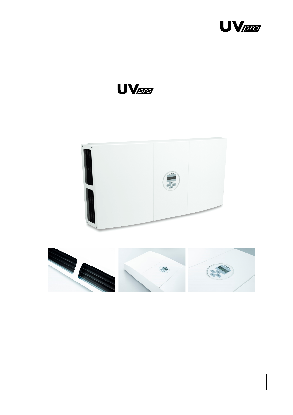
Recirculating Air Disinfection System V-lab
TABLE OF CONTENTS
1. SAFETY INSTRUCTIONS.................................................................................................... 3
DANGER ................................................................................................................................................................3
WHAT THE SYMBOLS MEAN.......................................................................................................................................3
TO BE AWARE OF BEFORE USAGE ................................................................................................................................4
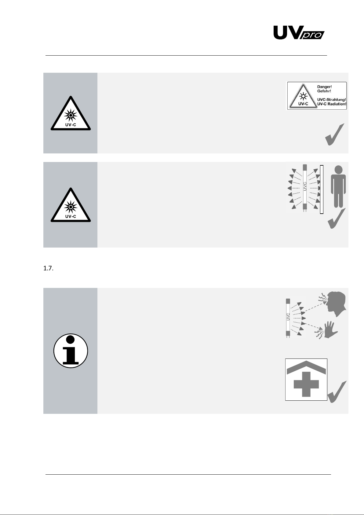
EMISSION ..............................................................................................................................................................5
AVOIDING DANGER .................................................................................................................................................5
MEASUREMENTS ON SITE..........................................................................................................................................6
IN CASE OF EMERGENCY ............................................................................................................................................7
2. TECHNICAL DATA AND DESCRIPTION OF THE SYSTEM ..................................................... 8
SPECIFICATIONS.......................................................................................................................................................8
SYSTEM DESCRIPTION...............................................................................................................................................8
3. ELECTRONIC COMPONENTS .......................................................................................... 10
ELECTRONIC COMPONENTS .....................................................................................................................................10
CONNECTION DIRECTLY OR WITH UVPRO MONITORING UNIT .........................................................................................10
DIMENSIONS AND SKETCH .......................................................................................................................................11
4. COMPONENTS OF THE SYSTEM ..................................................................................... 12
INSTALLATION INSTRUCTIONS...................................................................................................................................12
TUBE CHANGE.......................................................................................................................................................13
ELECTRICAL CONNECTION........................................................................................................................................16
POSITIONING AND DIMENSIONING ............................................................................................................................16
SKETCH HOLE PATTERN ...........................................................................................................................................16
5. OPERATION AND PROGRAMMING................................................................................ 17
COMMISSIONING AND MENU NAVIGATION.................................................................................................................19
MANUAL .............................................................................................................................................................19
DAILY TIMER.........................................................................................................................................................19
WEEKLY TIMER .....................................................................................................................................................20
6. PROBLEMS, CAUSES AND SOLUTIONS ........................................................................... 20
7. MAINTENANCE ............................................................................................................. 21
SAFETY INSTRUCTIONS FOR REPAIR WORK...................................................................................................................21
OPERATING TIME OF THE UVC TUBES........................................................................................................................22
MAINTENANCE OF COMPONENTS .............................................................................................................................23
ORIGINAL ACCESSORIES AND SPARE PARTS..................................................................................................................23
8. WARRANTIES ................................................................................................................ 24
9. DISPOSAL OF COMPONENTS ......................................................................................... 24
UVPRO TUBE ........................................................................................................................................................24
ELECTRONIC BALLAST WITH SCREW JOINT ...................................................................................................................24
10. ADDITIONAL INFORMATION ......................................................................................... 25
EC DECLARATION OF CONFORMITY ...........................................................................................................................25