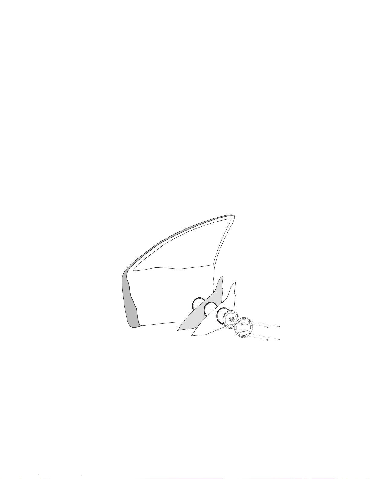
Orion CO40 User manual

Coaxial Speaker MODEL
CO40
CO46
CO52
CO57
CO60
CO65
CO653
CO68
CO69
CO693
OWNER'S MANUAL
™
TM

INSTALLATION
The performance of the Cobalt coaxial speakers is directly proportional to the
quality of installation. Care taken during the installation process will be
rewarded with years of satisfying performance. If you are unsure about your
installation capabilities, please refer to your local Authorized ORION Dealer
for technical assistance. ORION dealers are trained professionals dedicated
to obtaining the maximum performance out of your ORION system. If
you decide to install this speaker system yourself, please read the entire
installation section before starting your installation.
TOOLS OF THE TRADE
Listed are the majority of the tools required to perform the installation.
Having the proper tools will make the installation much easier. Some of these
tools are required.
•marking pen needle nose pliers
•wire crimpers •electric drill
•volt-ohm meter (opt.) wire strippers
•
1/8" drill bit wire cutters
•assorted tin snips •hole saw arbor
•Phillips screwdriver
•43/4" (120mm) hole saw (5"Coaxial installation)
•51/2" (140mm) hole saw (6" Coaxial installation)
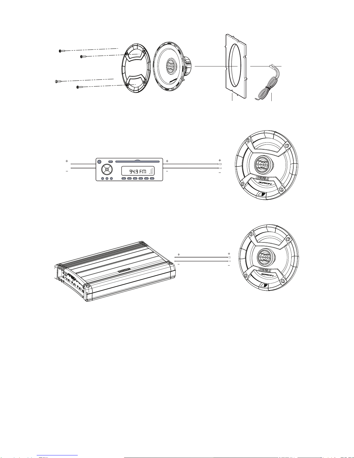
WHAT’S IN THE BOX
Included in this box are all the necessary mounting hardware and cables
for your basic installation. Listed below is a detailed list of the components
included in this system package.
Quantity Description
1 Installation and Operation Manual
1
1
Mounting template
2 Cobalt Coaxial Speakers
2 Grills (except for 4”, 6”, 4x6”,5x7”,6x8”)
Mounting Screws
•
•
•

FINDING SPEAKER MOUNTING LOCATIONS
Choosing the correct speaker locations will have the greatest effect on the
sound quality of the system. Different considerations are needed when choosing
the locations that best suit your needs. The locations must be large enough for
the speakers to fit. Care is needed to ensure that the location you have chosen
will not affect any of the mechanical or electrical operations of the vehicle.
Determining the best location for the speakers will depend on your cosmetic needs
and your vehicle's interior. If minimal intrusion in your vehicle is desired, factory
speaker locations may be the ticket for you. Placing the speaker in the factory location
can often give very desirable results.
DOOR MOUNTING
When checking for possible speaker locations in the doors, check the
operation of the window and all of the doors assemblies. There is also a
stabilizer stop bar in between the door and the door jamb. This bar prevents
the door from opening too far. Pay particular attention to this so you do not
damage the speaker when you close the door.
Figure 1
Figura 1
Abbildung 1
Stagger the holes for the wiring and use a rubber or
plastic grommet to protect the wire from damage
Figure 3
Dash
PanelTo the
amplifier
or source
unit
3
Inside
of Door
Speaker
cut out
Coaxial
Driver
Dampening Mat
Speaker installed
with no gaps
or air leaks
Dampening on
top of outer
door skin
Door
Panel
Rear/Trunk
of Car
Rear Seat
Grille Screws
REAR DECK MOUNTING
In rear deck installations, check the operation of the trunk suspension springs
or tension bars. These tension bars move in the opening and closing of the
trunk. You cannot be too cautious during this part of the installation, In
addition, do not locate the speakers too close to the back of the rear deck.
Mounting the far screws will only be possible with the removal of the rear
window.

Figure 2
Figura 2
Abbildung 2
Stagger the holes for the wiring and use a rubber or
plastic grommet to protect the wire from damage
Figure 3
Front Door
Body
Front Dash
Kick Panel
Speaker
cut-out
To the
amplifier
or source
unit
3
Inside
of Door
Speaker
cut out
Coaxial
Driver
Dampening Mat
Speaker installed
with no gaps
or air leaks
Dampening on
top of outer
door skin
Door
Panel
Rear/Trunk
of Car
Rear Seat
Grille Screws
STEP BY STEP INSTALLATION
Step 1: Determine where the speaker will be mounted. Make sure there is a
flat area large enough for the speaker to fit properly. An uneven
mounting surface can damage the driver.
Step 2: Check to make sure the space you have chosen for the speaker will
not interfere with the operation of the vehicle.
Step 3: Using a template, mark the speaker hole with a pen.
Step 4: Cut the hole for the speaker. When using factory locations, this step
can be passed. A hole can be cut either with a pair of metal tin snips
or a hole saw corresponding to the size of the speaker listed below.
• 43/4"(120mm)holesaw(51/4")
• 51/2"(140mm)holesaw(61/2")
Step 5: Run the speaker wire to the speakers. Make sure to keep wires away
from sharp metal or other edges. When passing through metal ,use a
protective grommet.
Step 6: Using the template, mark the mounting holes with a pen.
Step7:Pre-drillmountingholesusinga1/8" drill bit.
Step 8: Pull the wire through the speaker opening and connect to the
speaker.
Step 9: Mount the speaker and grill in the hole using the same screws. Insert
the screws through the grill and the mounting holes in the basket.
WARNING: Window mechanisms and electrical wires may be hidden
from sight. CHECK FOR CLEARING BEFORE YOU DRILL!

Flush Mount
Tweeter
Assembly
Tweeter
Cup
Pressure
Ring
Tweeter
Wire
Flush Mount
Trim Ring
Wiring
Harness
Panel
Wiring
Harness
Panel
Figure 3
Figura 3
Abbildung 3
AA
Other Channel Source Unit
Amplifier
Cobalt Coaxial wired
to a single channel
Cobalt Coaxial wired
to a single channel
stereo
Figure 4
Figura 4
Abbildung 4
Figure 5
Figura 5
Abbildung 5
AA
Other Channel Source Unit
Amplifier
Cobalt Coaxial wired
to a single channel
Cobalt Coaxial wired
to a single channel
stereo
Figure 4
Figura 4
Abbildung 4
Figure 5
Figura 5
Abbildung 5
* The Cobalt speakers can be powered by a head unit or an amplifier.
* Leshaut-parleursCobaltpeuventêtrealimentésparunrécepteurouun
amplificateur.
* Los altavoces Cobalt se pueden alimentar con una unidad principal o un
amplificador.
* Die Cobalt-Lautsprecher können von einem Autoradio oder einem
Verstärker betrieben werden.
* Gli altoparlanti Cobalt possono essere alimentati da una Head Unit o da
un amplificatore.
* Os alto-falantes de cobalto podem ser acionados por uma unidade
principal ou um amplificador.

SPECIFICATIONS
MODEL/PART NUMBER
Nominal Impedance
(ohms)
RMS/NOMINAL/MAX
music power (Watts)
RMS/NOMINAL/MAX
music power (Watts)
Frequency Response (Hz)
Sensitivity (dB)
Mounting Depth (inches)
Mounting Diameter
(inches)
MODEL/PART NUMBER
Nominal Impedance
(ohms)
Frequency Response (Hz)
Sensitivity (dB)
Mounting Depth (inches)
Mounting Diameter
(inches)
CO40
4
35/70/200
120 to 20k
86.2
1.81
4.55
CO46
4
35/70/200
110 to 20k
86.5
2.09
4.55
FEATURES
Cone moisture and UV resistant paper cone
Surround NBR (Nitrile butadiene rubber)
Voice Coil 2 layer copper clad aluminum wire on a Kapton former
Tweeter metalized PEI (Polyetherimide) - Ferrofluid
Spider single interlaced Conex
Stamped steel baskets with Euro mounting configurations
Two way systems have custom crossover with 6 dB high pass, 6 dB low pass and
tweeter protection
Swivel tweeter
NOTE: All specifications are subject to change without notice.
CO60
4
50/100/250
75 to 20k
87.3
1.73
5.61
CO52
4
50/100/250
90 to 20k
87.1
1.85
5.41
CO57
4
50/100/250
75 to 20k
87.9
2.15
5.1 x 7.1
CO65
4
50/100/250
62 to 20k
88.2
2.36
6.12
CO69
4
70/140/350
55 to 20k
88.8
2.95
6.1 x 8.75
CO693
4
80/160/400
55 to 20k
88.8
2.95
6.1 x 8.75
CO68
4
50/100/250
60 to 20k
88.5
2.52
5.1 x 7.5
CO653
4
60/120/300
62 to 20k
88.2
2.36
6.12

Figure 6
Figura 6
Abbildung 6
H
GF
I
E
D
A
B
C
H
GF
I
E
D
A
B
C
Dimensions inches/mm, Dimensions pouces/mm, Dimensiones plg./mm, Abmessungen Zoll/
mm, Dimensioni pollici/millimetri, Dimensões polegadas/mm
A
B
C
D
E
CO40
1.81/46
0.71/18
2.76/70
3.7/94
4/102
CO52
1.85/47
0.71/18
2.76/70
4.53/115
5.12/130
CO60
1.73/44
0.79/20
3.15/80
5.04/128
6.02/153
F
G
H
I
CO46
2.09/53
0.71/18
2.76/70
3.54/90
4.06/103
5.51/140
6.14/156
CO57
2.17/55
0.79/20
3.15/80
5.09/129
5.51/140
7.2/183
8.66/220

CO65
2.36/60
0.91/23
3.15/80
5.51/140
6.50/165
CO653
2.36/60
0.91/23
3.15/80
5.51/140
6.50/165
Dimensions inches/mm, Dimensions pouces/mm, Dimensiones plg./mm, Abmessungen Zoll/
mm, Dimensioni pollici/millimetri, Dimensões polegadas/mm
A
B
C
D
E
F
G
H
I
CO68
2.52/64
0.91/23
3.15/80
5.08/129
5.75/146
7.4/188
8.03/204
CO69
2.95/75
0.95/24
3.94/100
5.95/151
6.61/168
8.66/220
9.17/233
CO693
2.95/75
0.95/24
3.94/100
5.95/151
6.61/168
8.66/220
9.17/233
Orion Car Audio Speaker System
This manual suits for next models
9
Table of contents
Other Orion Car Stereo System manuals