CONTENTS
SERVICING
NOTICES
ON
CHECKING.
.............ssescscsscsseesessesseneessenneseesseersesanenseneeneess
Al-1
HOW
TO
ORDER
PARTS
.................05
Al-1
CONTENTS...
ceeeseeteeeeeeee
wee
AQ-1
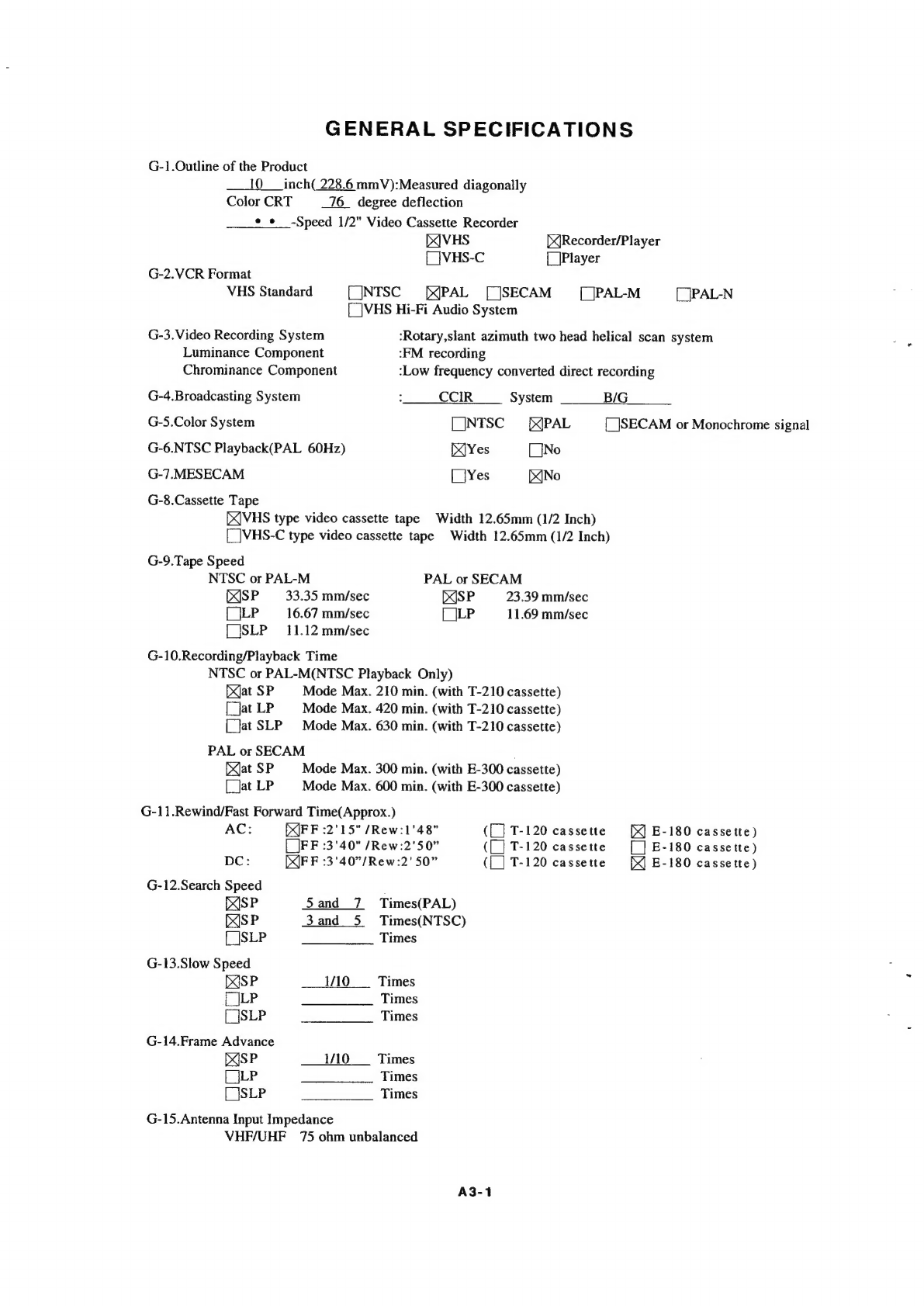
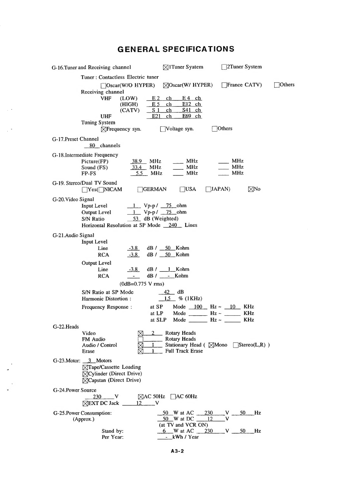
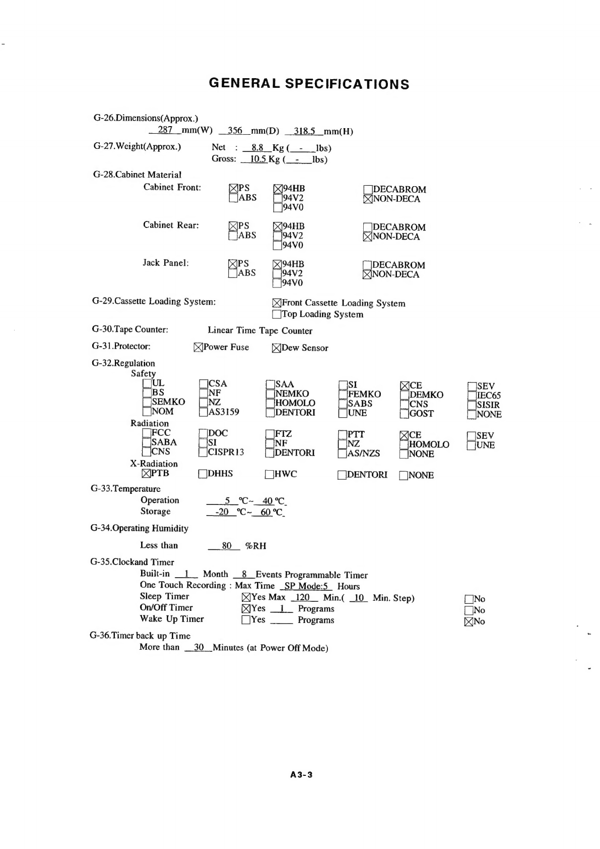
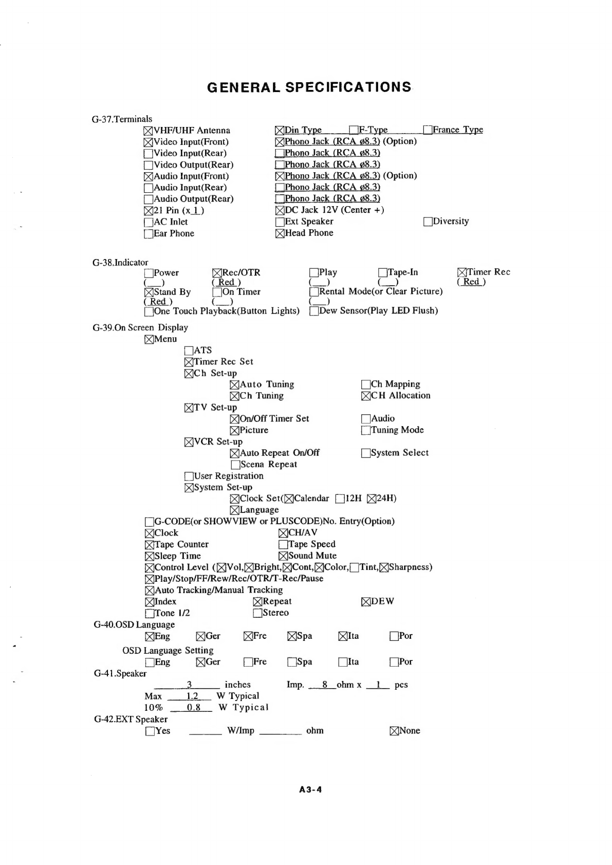
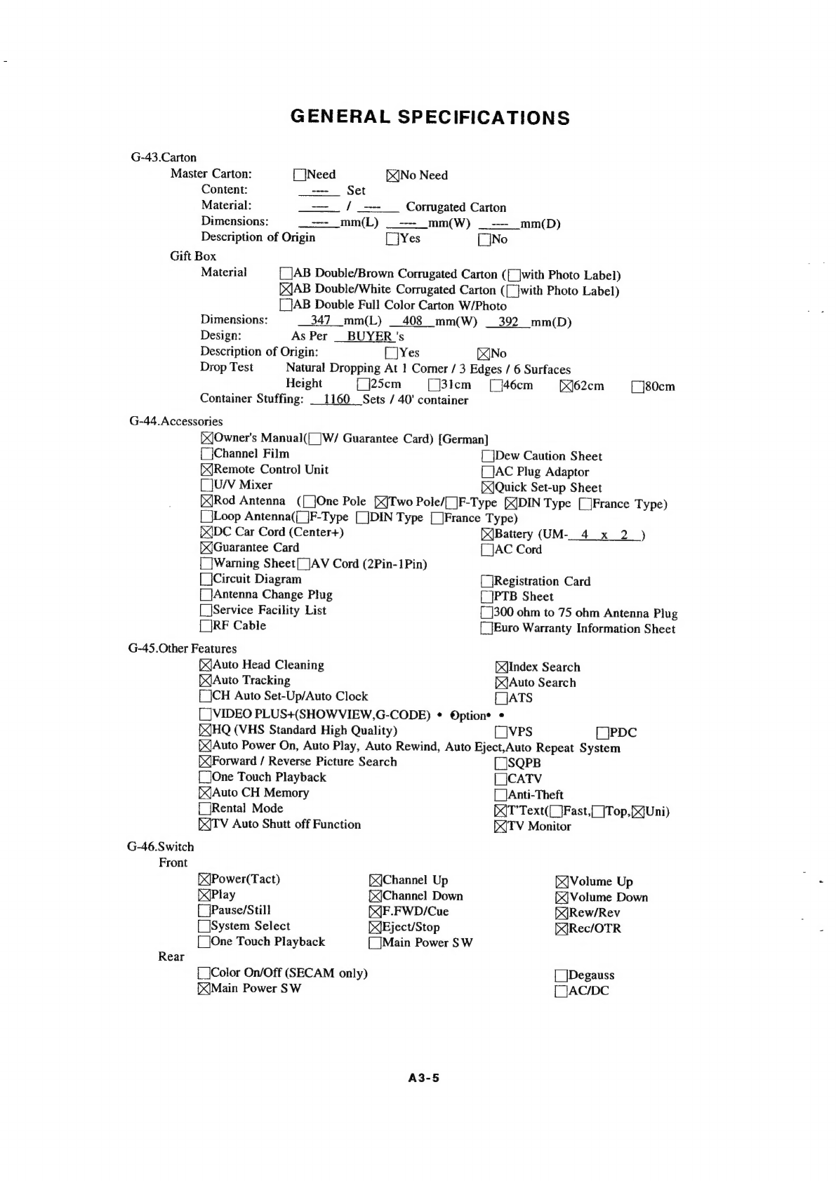
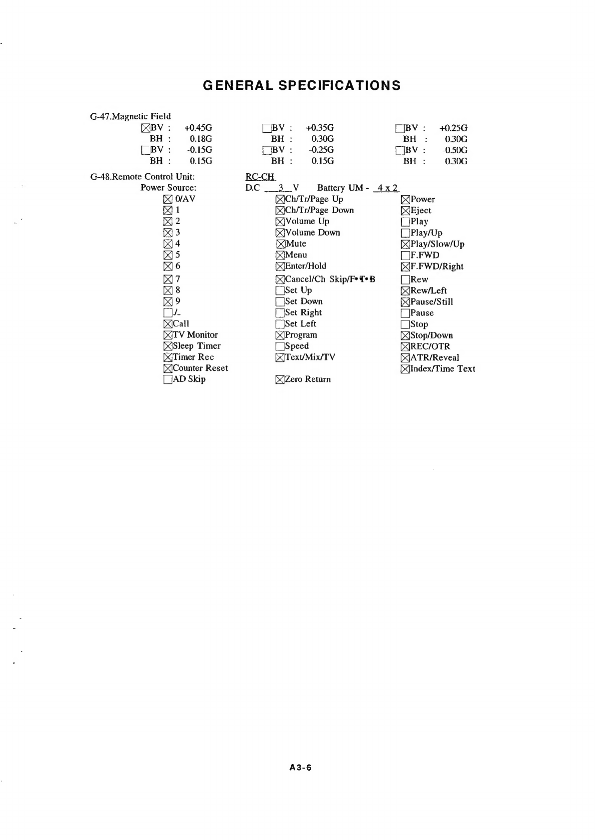
GENERAL
SPECIFICATIONS
A3-1~A3-6
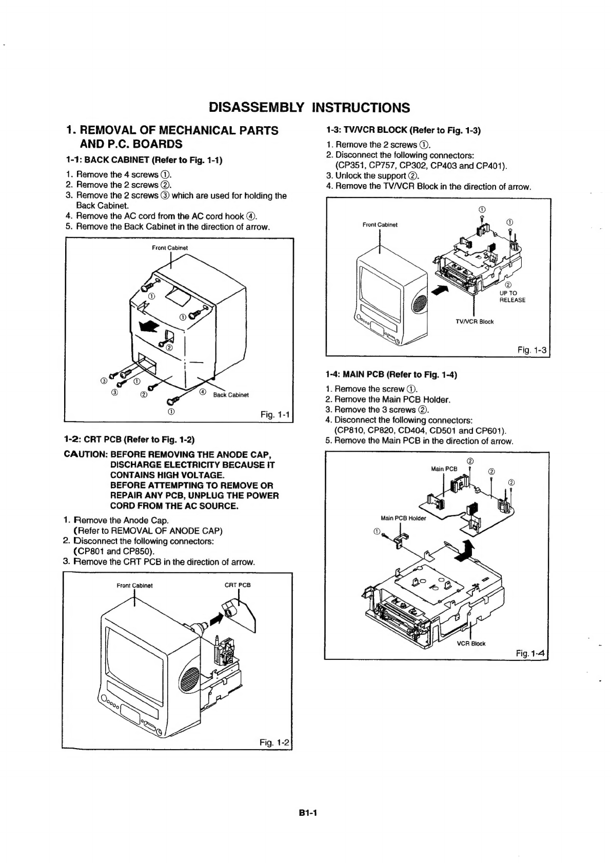
DISASSEMBLY
INSTRUCTIONS
1.REMOVAL
OF
MECHANICAL
PARTS
AND
P.C.
BOARDS
...........s.c:csccereseeeeeee
B1-1,
B1-2
2.REMOVAL
OF
DECK
PARTS
.......ecccessssssseesescnseseeeeseesenseesssseesseessseeeeaacenanseeseanace
B2-1~B2-5
3.REMOVAL
OF
ANODE
CAP
ou...
cescceseessessssesssseseessensessessenseseessseeasassanansesanesec®
B3-1,
B3-2
KEY
TO
ABBREVIATIONS
......
..
Ct-1,
C1-2
SERVICE
MODE
LIST
............cccscscesssscessessseeeeseeeees
..
C2-4
PREVENTIVE
CHECKS
AND
SERVICE
INTERVALS
NOTE
FOR
THE
REPLACING
OF
MEMORYIC
..
SERVICING
FIXTURES
AND
TOOLS
................
PREPARATION
FOR
SERVICING
..
.
C5-2
MECHANICAL
ADJUSTMENTS
..
..
D1-1~D1-4
ELECTRICAL
ADJUSTMENTS.
ote
eeeeececeesanecsenseseassenseeseserseseseneeeesnenteenenene
D2-1~D2-6
BLOCK
DIAGRAMS
PV
BE
OG
sich.
cocscescceatctesscccbsetsncudsesersuccascnecsectns
suede
rovend
soesrsoseotsctauy
acbesesstessdducesbecsoaehs
E-1,
E-2
Y/C/AUDIO/HEAD
AMP/21PIN/AIN/OUT
..
.
E-3,
E-4
MICON/POWER/OPERATION
..
..
E-5,
E-6
PMB,
Siscsetivcccsctsesecsnedcsdntirasessuuetcnswdusdcpsveussccscavestrsedeetpnendesbivoesvsoiecuesdeatustzcviecddseue
E-7,
E-8
PRINTED
CIRCUIT
BOARDS
MAINIGRID
sssesecesopsdccesssceconssnscsssnoscsceceaccecacabeccadarteassetsesesbnanedeisaceussoeonSuccsenetscteosbvesbetps
F-1,
F-2
SYSCON....
.
F-3~F-6
OPERATIONIDEGK.
4
sveshssiscceceseccscesncecedensecesesaesstocvsteseesenssinssed
susie
sausucedecsthassensseczcnns
F-7,
F-8
SCHEMATIC
DIAGRAMS
Y/CIAUDIO/HEAD
AMP.
............sssscsssesssssessssscscersssessssssssessescesseceseeecessseresseuonsensacasans
G-1,
G-2
MICON
ou.
cee
ccceseetseeeeeeseeseoes
aoe
.
G-3,
G-4
POWER
ue
scscseseseeescsssessssenenaseenens
vee
.
G-5,
G-6
21PINAN/OUT
.
G-7,
G-8
CHROMAIIF
......
.
G-9,
G-10
SOUND
AMP
1...
ccccsssnesesnsssssssesesesenesessesseeesessesceneeeenesessseseaesaeseaeatsnssessanesseesenasenenes
G-11,
G-12
TTEXT
.......
wee
G-13,
G-14
TV
POWER...
.
G-15,
G-16
DEFLECTION
G-17,
G-18
CRT
....sseeeeeeee
G-19,
G-20
OPERATION
..
.
G-21,
G-22
DECK
oo
sctscssiceitensticicmetedetiecss
.
G-23,
G-24
INTERCONNECTION
DIAGRAM
.
.
G-25,
G-26
WAVEFORMS
.............:.ccseccsseseeeeeneee
MECHANICAL
EXPLODED
VIEWS
.
.
11,
1-2
CHASSIS
EXPLODED
VIEWS.
...............:0:00
.
1-3,
1-4
MECHANICAL
REPLACEMENT
PARTS
LIST
.
.
J1-1
CHASSIS
REPLACEMENT
PARTS
LIST
.........
J2-1
ELECTRICAL
REPLACEMENT
PARTS
LIST
ow...
eee
ccceeneteeeeee
tenes
..
J3-1~J3-3