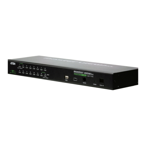
osprey video MSS-8 Guide

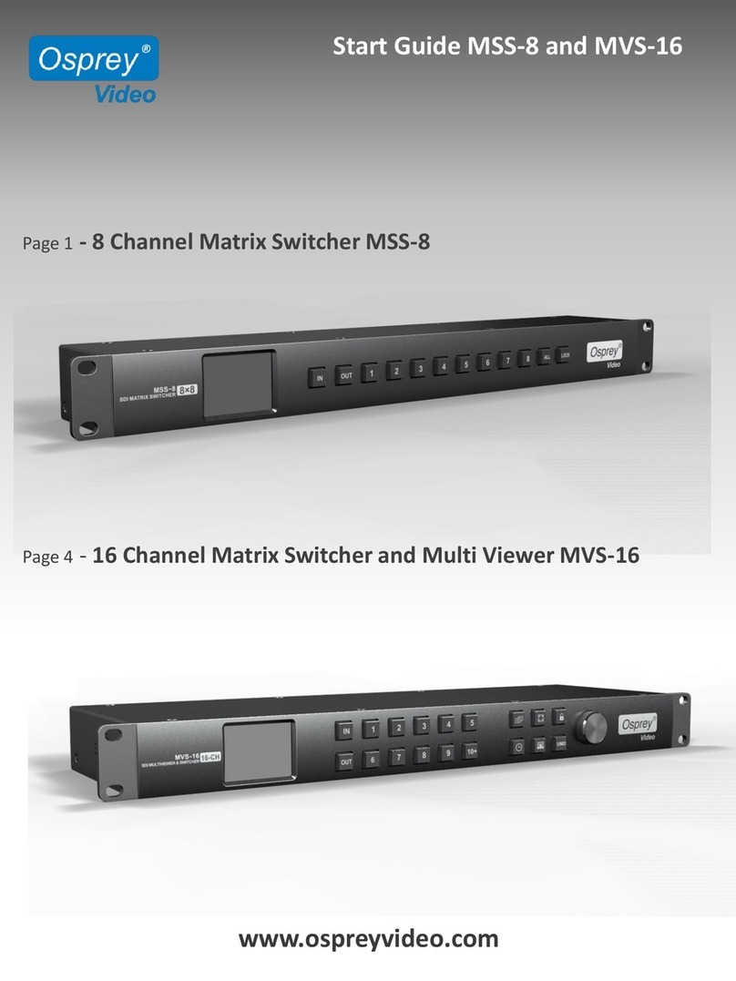
Start Guide MSS-8 and MVS-16
Page 1 - 8 Channel Matrix Switcher MSS-8
www.ospreyvideo.com
Page 4 -16 Channel Matrix Switcher and Multi Viewer MVS-16

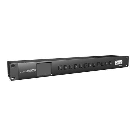
RACKMOUNT 8x8 MATRIX SWITCHER
MSS-8
Initial Setup
Power Connections:
MSS-8 is supplied with two 12V Wall Power Supplies. One Power Supply is sufficient
to power the MSS-8, however for redundancy we recommend both Power Supplies to
be used simultaneously.
LAN Connection:
MSS-8 has been designed to work seamless with any DHCP Server. A Static IP can be
assigned using the Software Control Utility.
RS232 Connection:
Port Settings: Bps 9600, Data bits 8, Parity None, Stop Bits 1, Flow Control None
Setup:
•Download and Install the Osprey control panel software
•Connect Unit to your PC using RS232 or to your network using LAN
•Connect your video sources and video sinks to the SDI Inputs/Outputs
•Connect Power and turn unit ON
www.ospreyvideo.com
1

RACKMOUNT 8x8 MATRIX SWITCHER
MSS-8
Manual Keypad Controls
Using the Buttons on MSS-8 Front Panel
IN/OUT: Make individual Matrix Connections
Example Sequence: IN –2 –OUT –4 –6 –7 (Input 2 connected to
Outputs 4, 6 and 7 )
ALL: Connect one Input to all Outputs simultaneous
Example Sequence: IN –4 –ALL (Input 4 connected to all 8 Outputs)
LOCK: Keypad Lockout
Display: The first line represents Outputs 1-4, the second line Outputs 5-8.
SIP: Static IP Address
DIP: Dynamic IP Address (DHCP)
Above display shows the following connections.
- Input 1 to Outputs 5, 6, 7, 8
- Input 2 to Outputs 1, 2, 3, 4
The display brightness can be adjusted using the PC based Osprey
Control Software. There is also a “sleep” option.
www.ospreyvideo.com
2
Input Select Output Select Channel # One to All Keypad Lockout

RACKMOUNT 8x8 MATRIX SWITCHER
MSS-8
Software Controls
Using Osprey Control Panel Software
SCANNING: Scans the Network for all connected Osprey MSS-8 and MVS-16
SETTING: Switch between LAN (Static or DHCP) or Serial Connection
LOCK: Lockout of the Unit Keypad to prevent unwanted I/O changes
INPUT: Selection of Input Channel
OUTPUT: Selection of Output Channel
APPLY: Applies the I/O Selections
STATUS: I/O Connections. Left to right shows Outputs 1 through 8
REFRESH: Updates the I/O status in the Software Interface to capture Changes
made on the keypad while the Software was running
ONE to ALL: Simultaneous connect one Input to all Outputs
ONE to ONE: Simultaneous connect Input 1 to Output 1, Input 2 to Output 2,etc
BACKLIGHT: Change brightness and behavior of the Units Display
www.ospreyvideo.com
3

Initial Setup
Power Connections:
MVS-16 is supplied with two 12V Wall Power Supplies. One Power Supply is sufficient
to power MVS-16, however for redundancy we recommend both Power Supplies to
be used simultaneously.
LAN Connection:
MVS-16 has been designed to work seamless with any DHCP Server. A Static IP can be
assigned using the Software Control Utility.
Setup:
•Download and Install the Osprey control panel software
•Connect Unit to your network using LAN
•Connect your video sources and video sinks to the SDI Inputs/Outputs
•Connect Power and turn unit ON
www.ospreyvideo.com
4
16 CHANNEL MULTIVIEWER
16x16 MATRIX SWITCHER
MVS-16

16 CHANNEL MULTIVIEWER
16x16 MATRIX SWITCHER
MVS-16
Manual Keypad Controls
Using the Buttons on MVS-16 Front Panel
1: Display to show Device Status and Menu Controls
2: MultiViewer Mode
Assigning an Input to a Window.
Example: IN –1 –OUT –1 –2 assigns Input 1 to Windows 1 & 2
Switcher Mode
Make individual Matrix Connections
Example Sequence: IN –2 –OUT –4 –6 –10+ –2 connects Input 2
to Outputs 4, 6 and 12 )
3: Turns Time Code On/Off for all Channels
4: Turns Audio Meters On/Off for all Channels
5: Turns Channel ID On/Off for all Channels
6: Toggle between 20 different MultiView Layouts
7: Turn On Full Screen Mode. Then select channel for full screen view of
selected channel
8: Keypad Lockout
9: Menu Controls - Push to Enter Menu
Note: Multiviewer Mode vs. Switcher Mode only affects the functionality of the
buttons “2” as shown above. The Mode can only be changed in the menu
settings using rotary button “9”.
www.ospreyvideo.com
5
1 2 3 4 5 9
678

Front Panel Menu Controls
Push Rotary Button on Front Panel to access the System Menu
www.ospreyvideo.com
6
Main Menu Sub Menu Options Description
System Setting
Language
English/Chinese
Change the Language between Chinese and
English
LCD brightness
10
-100
Set the backlight brightness between 10
-100
LCD ON/OFF
Always/ Off/ Dim
Set the state of backlight,there are three mode for
option: Always/Off/ Dim
LCD Sleep
5~60s
Set backlight time of “Off” and “Dim”
Reset
Reset to default configuration
Custom1
Load Custom1 configuration
Custom2
Load Custom2 configuration
Return
Back to the main menu
Network
Setting
IP Acqui
Dynamic/Static
Two ways to acquire the IP:
Static or Dynamic
IP Addr
Set the IP address
NetMask
Default setting is 255.255.255.0
GateWay
Set Gateway according to current IP address
Save
Save network setting
Return
Back to the main menu
Overlay Setting
Item Select
UMD/Input Resolu/Audio Meter/Time
Code/Border/Audio Alarm
Select a certain overlay
Win/Source
1~16
Select a Window or signal source for each setting
Enable
On/Off
On/Off the selected overlay
Text Color
Yellow/White/Gray/Violet Red/Light Blue/Light
Green/Light Cyan/Light Yellow/Transparent
HalfTrans/Black/Blue/Red/Magenta/Green/Cyan
Text color setting
Background
Yellow/White/Gray/Violet Red/Light Blue/Light
Green/Light Cyan/Light Yellow/Transparent
HalfTrans/Black/Blue/Red/Magenta/Green/Cyan
Background color setting
Return
Back to the main menu
Audio Setting
Audio Source
WIN1~WIN16
Select the audio source of multiviewer output
Audio Meter
1~16
Select a certain window for audio meter setting
Channel
CH1&CH2
CH3&CH4
CH5&CH6
CH7&CH8
CH9&CH10
CH11&CH12
CH13&CH14
CH15&CH16
Set the audio channel of audio meter
Return
Back to the main menu
16 CHANNEL MULTIVIEWER
16x16 MATRIX SWITCHER
MVS-16

www.ospreyvideo.com
7
Output Setting
Format
1080P60/1080P50/1080P30/1080P25/1080P24/1080I60
1080I50/720P60/720P50
Set the output formats
Mode
Multiviewer/Switcher
Change the mode between Multiviewer and Switcher
SDI Loop Out
Under "Matrix Switcher" mode, set all input and output
channels correspond one by one
Return
Back to the main menu
Device
Info
Version
Current version information
Return
Back to the main menu
Exit
Exit main menu
16 CHANNEL MULTIVIEWER
16x16 MATRIX SWITCHER
MVS-16
Osprey Control Panel Software
SCANNING: Scans the Network for all connected Osprey MSS-8 and MVS-16
SETTING: Switch between LAN (Static or DHCP) or Serial Connection
LOCK: Lockout of the Unit Keypad to prevent unwanted I/O changes
LAYOUT: Selection of MultiView Output Layout
SWITCHER: Control of 16x16 Matrix Connections
UMD: Customize Channel Names
AUDIO: Audio Meter Enable/Disable, Audio Meter Channel Selection
Selection of Audio Source for MultiView Output Embedding
COLORS: Customize colors of Text and Video Information Overlay
CONTROLS: Enable/Disable Video Information Overlay
Enable/Disable Audio Alarm
Enable/Disable Timecodes
Save/Load Custom Profiles
Other manuals for MSS-8
2
This manual suits for next models
1
Table of contents
Other osprey video Matrix Switcher manuals
