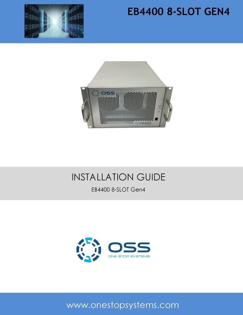
OSS EB4400 5-SLOT Gen4 User manual

INSTALLATION GUIDE
EB4400 5-SLOT GEN4
EB4400 5-SLOT Gen4
www.onestopsystems.com

One Stop Systems
EB4400 (5-SLOT BP) 2
Table of Contents
1Introduction................................................................................................................................................................... 5
1.1 General Specifications...............................................................................................................................................................................5
1.2 Features ....................................................................................................................................................................................................6
1.3 EB4400 Architecture (5 Slot) ..................................................................................................................................................................... 6
1.4 PCIe Slots .................................................................................................................................................................................................. 6
1.5 Backplane Block Diagram..........................................................................................................................................................................7
1.6 Dimensions................................................................................................................................................................................................8
1.7 Parts Overview.......................................................................................................................................................................................... 9
1.8 HIB x16 Gen 4 Card ................................................................................................................................................................................. 11
1.9 Backplane................................................................................................................................................................................................12
1.10 Slot Configurations ............................................................................................................................................................................13
1.11 Use Case Diagrams ............................................................................................................................................................................14
1.12 Main Components ............................................................................................................................................................................. 15
1.13 Pre-Installation Information ..............................................................................................................................................................15
1.14 Tools Required for Installation........................................................................................................................................................... 15
1.15 Items List ...........................................................................................................................................................................................15
2Getting Started .............................................................................................................................................................16
3Installation Overview ....................................................................................................................................................16
4Hardware Set-up / Installation ......................................................................................................................................17
4.1 Remove Top Cover..................................................................................................................................................................................17
4.2 Install Target Card ...................................................................................................................................................................................17
4.2.1 Target Card Configuration ................................................................................................................................................................. 17
4.3Install Host Card......................................................................................................................................................................................18
4.3.1 Host Card Configuration...............................................................................................................................................................18
4.4 Dip switch Settings.................................................................................................................................................................................. 20
5GPU / PCIe Cards Installation ........................................................................................................................................21
5.1Before you begin ...............................................................................................................................................................................22
5.2 Install GPU or PCIe card ..........................................................................................................................................................................22
5.3 Connect Auxiliary Power Cables............................................................................................................................................................. 23
6Connect Link Cables ......................................................................................................................................................25
6.1 Mini-SAS HD SFF-8644 Cable Installation ................................................................................................................................................25
6.1.1 x16 Configuration: FOUR cables ................................................................................................................................................... 25
6.1.2 x8 Configuration: TWO cables ......................................................................................................................................................26
6.1.3 x4 Configuration: ONE cable......................................................................................................................................................... 27
6.2 Disconnecting Mini-SAS HD SFF-8644 Cable............................................................................................................................................28

One Stop Systems
EB4400 (5-SLOT BP) 3
7Applying Power Correctly..............................................................................................................................................29
7.1 Connecting to electrical outlet................................................................................................................................................................29
7.2 Connect Power Cord(s) ...........................................................................................................................................................................29
8Powering UP the Computer...........................................................................................................................................31
9Hardware Check............................................................................................................................................................32
9.1 Verify Board LEDs.................................................................................................................................................................................... 32
9.2 Fault LEDs (RED)......................................................................................................................................................................................33
9.3 Verify Adapter Card LEDs ........................................................................................................................................................................34
9.4 Adapter Card LED Definitions..................................................................................................................................................................35
9.5 Slot LEDs.................................................................................................................................................................................................. 35
9.6 Power Distribution Board LED.................................................................................................................................................................36
9.7 Front LED................................................................................................................................................................................................. 36
9.8 Power Supply LED Indicator ....................................................................................................................................................................37
10 Software Installation.....................................................................................................................................................38
10.1 Software Driver Installation...............................................................................................................................................................38
11 Verify HIB Device ..........................................................................................................................................................39
11.1 Linux OS............................................................................................................................................................................................. 39
11.2 Windows 10 / Server .........................................................................................................................................................................41
11.2.1 HIB Cards and Backplane..............................................................................................................................................................41
12 Verify PCIe cards ...........................................................................................................................................................43
12.1 Linux ..................................................................................................................................................................................................43
12.2 Windows............................................................................................................................................................................................44
13 IPMI ..............................................................................................................................................................................46
13.1 Connect Ethernet Cables ...................................................................................................................................................................46
13.2 Locate Mac Address & IP Address...................................................................................................................................................... 47
13.3 Start Internet browser .......................................................................................................................................................................48
14 Other Technical Information .........................................................................................................................................49
14.1 Upstream and Downstream Slots ......................................................................................................................................................49
14.2 Slot LEDs ............................................................................................................................................................................................ 49
14.3 Board LEDs.........................................................................................................................................................................................50
14.4 Slot Type............................................................................................................................................................................................ 50
14.5 PS_ON................................................................................................................................................................................................50
14.6 ARF6 Connector.................................................................................................................................................................................51
14.6 Slot Number and Port Mapping......................................................................................................................................................... 51
14.7 Power Cords ......................................................................................................................................................................................52
14.7.1 Specifications ............................................................................................................................................................................... 52
14.7.2 Power cord socket and voltage tables world standards ...............................................................................................................52

One Stop Systems
EB4400 (5-SLOT BP) 4
14.8 Power Supply.....................................................................................................................................................................................53
14.9 Removing AC Power Supply...............................................................................................................................................................54
14.9.1 Specifications ............................................................................................................................................................................... 55
14.9.2 LED Indicator ................................................................................................................................................................................56
14.10 Fan.....................................................................................................................................................................................................57
14.10.1 Fan Specifications ........................................................................................................................................................................... 57
14.10.2 How to remove Fan........................................................................................................................................................................58
14.11 Fan Foam Air Filter...........................................................................................................................................................................58
14.12 Auxiliary power cables.......................................................................................................................................................................59
14.12.1 Aux power cable installation................................................................................................................................................... 60
14.12.2 Pin Outs...................................................................................................................................................................................61
14.12.3 Using the Auxiliary Power Cable ............................................................................................................................................ 63
14.13 Expansion Unit Power Consumption ................................................................................................................................................. 65
14.14 Power consumption breakdown per hardware .................................................................................................................................65
15 Troubleshooting............................................................................................................................................................66
15.1 Device is not detected or recognized.................................................................................................................................................66
15.2 My PCIe devices are showing UP with a Yellow Exclamation mark....................................................................................................66
15.3 No link between host and target cards..............................................................................................................................................66
15.4 Broken OSS-Backplane.......................................................................................................................................................................66
15.5 My PCIe cards are not detected.........................................................................................................................................................66
15.6 Windows Error Codes ........................................................................................................................................................................67
15.7 System board fails to power UP.........................................................................................................................................................67
15.8 PCIe Upstream and Downstream Ports are not detected..................................................................................................................68
15.9 Support for 3rd Party PCIe Cards ........................................................................................................................................................ 68
16 How to Get More Help ..................................................................................................................................................69
16.1 Contacting Technical Support ............................................................................................................................................................69
16.2 Returning Merchandise ..................................................................................................................................................................... 69
16.3 Third Party Hardware & Software Support Policy..............................................................................................................................69
16.4 Online Support Resources ................................................................................................................................................................. 69

One Stop Systems
EB4400 (5-SLOT BP) 5
1 Introduction
This 5-slot expansion platform provides PCIE expansion in a dense, rugged form factor. The EB4400 supports ONE or TWO PCIe 4.0 x16 host
connections to PCIe 4.0 slots from 1m to 2m away from the host server. The system supports 4 dual-width or 7 single-width full-length PCIe
add-in cards (AICs) such as GPU card, NVME flash and industrial I/O. Two PWM Fans providing high-power add-in card cooling up to 350W per
AIC. Two 1600W or 2600W power supplies provide redundant hot-swap system power with either AC or DC input.
1.1 General Specifications
Item
Description
System
4U Custom Form Factor (10.7” x 7.0” x 18.5”) Net weight 25 lbs.
Host Options
1x PCIe4 x16 Host-to-Target uplink
(32 GB/s)
2x PCIe4 x16 Host-to-Target uplinks
(64 GB/s)
SmartNIC Host
Backplane Options
OSS-538:
1x single-width PCIe 4.0 x16 FHFL upstream slot
4x dual-width PCIe 4.0 x16 FHFL downstream slots
OSS-521:
1x single-width PCIe 4.0 x16 FHFL upstream slot
6x single-width PCIe 4.0 x16 FHFL downstream slots
1x dual-width PCIe 4.0 x16 FHFL downstream slot
Slot Configuration Options
Flex
Modifies one dual-width PCIe 4.0 x16 FHFL
downstream slot to two single-width PCIe
4.0 x16 FHFL downstream slots per
backplane
Riser
Adds an additional single-width PCIe 4.0
FHFL downstream slot per backplane
Environmental Specifications
Temperature:
Operating temp 0 ° to 35 °C ambient.
Short-term (30 mins) operating temp –5°C to 40°C ambient.
Storage temp –40°C to 70°C.
Operational Humidity:
Operating humidity 5-95% (non-condensing)
Storage humidity 0-95% (non-condensing)
Operational altitude:
Operating altitude 6000 ft. at operating temp, 15,000ft. at derated temp. Storage altitude 40,000 ft.
Fans:
3x 180CFM 92mm fans
Default PWM controlled based on built-in temperature sensors
Optional IPMI system monitoring and control
Power Options
Single/Dual AC 1600W
Single/Dual DC 1600W
System Monitoring
Default –automatic dynamic temperature-based fan
speed control
Optional–IPMI system monitoring with power,
temperature, and fan speed control and monitoring
Fan Filters
Optional Quadra foam 45 PPI Replaceable Fan Filters
PCIe 4.0 Cable Lengths
1m
2m
3m
Power Cords
6’ US 110V
6’ US 240V
6’ UK
2’ IEC
6’ IEC
Agency Compliance
Agency Certifications (testing pending):
FCC Class A
CE Safety & Emissions
UL, Cul
RoHS3
Warranty
1 Year Return to Factory. Extended Warranty is available and sold separately.
Upon purchased of a new unit you can buy an extended warranty.

One Stop Systems
EB4400 (5-SLOT BP) 6
1.2 Features
PCIe Gen4 architecture
Small, rugged frame design
Dynamic fan speed control
Configurable slot and host uplinks to optimize throughput
Integrated IPMI based systems monitoring
AC and DC power inlet options
1.3 EB4400 Architecture (5 Slot)
1.4 PCIe Slots
Slot Type: Closed-ended PCIe slot / connector, all the slots are x16 mechanical.
Six x8 electrical slots (slots 1, 2, 3, 4, 5 and 6)
Three x16 electrical slots(slots 0, 7 and 8)

One Stop Systems
EB4400 (5-SLOT BP) 7
1.5 Backplane Block Diagram

One Stop Systems
EB4400 (5-SLOT BP) 8
1.6 Dimensions

One Stop Systems
EB4400 (5-SLOT BP) 9
1.7 Parts Overview

One Stop Systems
EB4400 (5-SLOT BP) 10

One Stop Systems
EB4400 (5-SLOT BP) 11
1.8 HIB x16 Gen 4 Card
x4 cable Ports
There are four x4 cable ports /connectors available on the HIB Gen4 card. Port #0 is located nearest to the Link LED.
A single x4 SFF-8644 cable must be inserted into port#0 of the Target card.
On the Host card side, you can plug in a single x4 cable to any port as long as the Host card switch is set to x4 mode.
When using two x4 SFF-8644 cables, it must be connected to port#0 and port#1 of the Target card only.
On the Host card side, plug-in the two cables to port#0 and portt#1 OR port#2 and port#3.

One Stop Systems
EB4400 (5-SLOT BP) 12
1.9 Backplane
Item
Name
Description
1
12V Input Power
12V input power for the 538 board. Not to be used for external GPU aux.
2
ARF 6 Top Connectors
For connecting ARC 6 cables between ”Option slot” and PEX switch
3
I2C and temp sensors interface
Connector for I2C and temp sensors interface to the power backplane
4
Ethernet port
Not used
5
Passive Heat sink
Moves heat away from the PCIe chip
6
PCIe Downstream Slots / Port
PCIe card slot for 3rd Party PCIe cards
7
Option Slot
Configurable card slot to operate either as an Upstream or Downstream modes
8
Card Slot LED
LED status indicator when slot is populated or not. Solid green when card is present. Off, when no
card.
9
Target Slot LED
LED status indicator for Target card. Solid green when Gen 4 adapter card is installed
10
Upstream Port / Target Slot
Designated slot for Target card only
11
Dip Switches
For slot configuration
12
Board LEDs
LED status indicator for the board
13
FPGA Connector
FPGA Programming connector
14
PS_ON
Enable to force power ON the backplane by placing a jumper on the connector
15
Temperature Sensor
Sensor for detecting temperature on the board
16
24-pin ATX Power Connector
For connecting ATX Power Supply
17
PCIe Switch Port
PCIe switch management port, optional
18
ARF 6 Bottom Connectors
For connecting ARC 6 cables between ”Option slot” and PEX switch
19
Screw-Mounting Holes
For securing the board on to an enclosure

One Stop Systems
EB4400 (5-SLOT BP) 13
1.10 Slot Configurations
Configuration# 1: Default slot configuration. One Upstream slot and five Downstream slots.
You must have the ARC6 cables attached between the edge of the board and the slot connectors under the backplane. Without those ARC6
cables nothing will work in SLOT 5.
Configuration# 2: Two Upstream slots (Slot 0 and SLOT 5) with two partitions.
Slot 0: Partition #1 with two Downstream slots
Slot 5: Partition #2 with two Downstream slots

One Stop Systems
EB4400 (5-SLOT BP) 14
1.11 Use Case Diagrams
Configuration 1
OSS-538 backplane is linked to a single host computer.
Four x4 link cables are connected between OSS Gen4 Host card and Target card.
4 Downstream slots and 1 Option slot
4 x16 slots (Slot 1, 2, 3 and 4 )
Configuration 2
OSS-538 backplane is linked to two host computers, see diagram below.
Two partitions / two Upstream slots (Slot 0 and SLOT 5) with a total of 4 downstream slots.
Slot 0: Partition #1 with two Downstream slots
o2 x16 slots (Slot 1 and 2)
Slot 5: Partition #2 with two Downstream slots
o2 x16 slots (Slot 3 and 4)

One Stop Systems
EB4400 (5-SLOT BP) 15
1.12 Main Components
a. The EB4400 unit is composed of following major components
b. 5-slot Backplanes (OSS-538)
c. One or Two Target Cards : PCIe 4.0 x16
d. One or Two Host Cards: PCIe 4.0 x16 (Installed in the host systems)
e. Four or eight SFF-8644 PCIe Gen4 PCIe Cables
f. One or Two 1600W or 2600W Power Supplies
g. Two 92 x 92 x 32mm fans
h. Features including additional hosts, filters, or system monitoring are configurable.
1.13 Pre-Installation Information
Before using the One Stop Systems expansion unit, you should perform the following steps:
Inventory the shipping carton contents for all of the required parts
Gather all of the necessary tools required for installation
Read this manual
1.14 Tools Required for Installation
To complete the installation of the product you will need a Phillips-head screwdriver and ESD wrist strap to prevent electrostatic discharge.
1.15 Items List
Item
Qty
Description
1
2 or 4
Full-height PCI Express Adapter Cards
2
4 or 8
SFF –8644 x16 PCIe Gen4 cable
3
1 or 2
U.S. Standard 125V or 250V

One Stop Systems
EB4400 (5-SLOT BP) 16
2 Getting Started
Installation procedure on how to set up the expansion unit. You will find instructions for the following procedures:
•How to Remove Top Cover
•Target Card Installation
•Host Card Installation
•GPU / PCIe Cards Installation
•Mini-SAS HD SFF-8644 cable Installation
•Powering Up the unit / system
•Hardware LED Check
•Device Verification via OS
3 Installation Overview
1. Remove the top cover.
a. Check inside the unit for loose components or damaged parts.
2. Check the Target card, make sure it is firmly installed and secured.
a. By default, the Target is already installed in the unit. If the Target card is not installed or missing, please go to section on
how to install the target card.
3. Install the Host card.
a. You should have another card that is configured as host card.
b. Check the dipswitches make sure it is set to host mode prior to installing the card.
4. Install PCIe / GPU cards.
a. Plug in your PCIe or GPU cards in the expansion unit.
5. Connect the external link cables.
a. Plug in the Mini-SAS HD SFF-8644 cables between Target and Host cards.
6. Connect the power cords.
a. The unit is supplied with power cord(s). You should have either one or two, depending on the number of power supplies
installed in the unit.
b. The standard unit is assembled with AC power supplies installed.
7. Power ON the host computer.
8. Check the hardware by verifying all LED status indicators.
a. Boards LED
b. Target & Host cards
c. Unit front power LED
d. Power supplies LED
9. Check the OSS devices via operating system, verifying all OSS devices are properly recognized.

One Stop Systems
EB4400 (5-SLOT BP) 17
4 Hardware Set-up / Installation
The following steps will guide you through the installation of your One Stop Systems expansion system.
4.1 Remove Top Cover
Remove the two (2) mounting screws on top of the chassis. Slide the enclosure cover towards the back of the unit to disengage it from the
guides and then lift the cover off.
4.2 Install Target Card
By default, the Target card is installed in the unit. The Target card is plugged in or installed in the Target slot. If the Target card is missing or not
installed, follow these steps.
Configure the card first; set the card switches to Target mode.
Plug in the Target card in the designated target slot (upstream slot) of the expansion system.
4.2.1 Target Card Configuration
SW1 #1 = ON; #2= ON
SW2 = All OFF

One Stop Systems
EB4400 (5-SLOT BP) 18
Once the dipswitches are set correctly, plug in the target card, make sure it is fully seated in the PCie slot.
4.3 Install Host Card
Before installation, you must check the switches on the Host card.
By default, all the switches on the Host card are set to OFF position (“Auto-Negotiation” mode).
You can leave the switches to default or you can set the switches (SW1 and SW2) on the card for the desired Host operating mode.
See “Host Card Configuration” section for more details.
4.3.1 Host Card Configuration
The following are switch settings for the Host card.
x16 Dip switch Settings:
SW1 #2 = ON; #5 =ON.
SW2 #1 = ON; #2 = ON
x8 Dip switch Settings:
SW1 #2 = ON; #5 = ON
SW2 #1 = OFF; #2 = ON or #2 = OFF and #1 = ON

One Stop Systems
EB4400 (5-SLOT BP) 19
x4 Dip switch Settings:
SW1 #2 = ON; #5 = ON
SW2 = All OFF
Once the Host-card is configured, install the card into a x16 Gen4 PCIe slot on a computer motherboard.
Check the PCIe slot for any foreign debris as this can damage the card during installation.
Align the host card PCIe connector on top of the PCIe slot and carefully push the card down until it is firmly seated.
Secure the card with the screw.
Below photo is an example of a x16 PCIe slot connectors. The photo on the right is a PCI-E 3.0 x16 slot. The specification of the PCIe slot is
printed on the board next to connector for easy identification. Use a x16 PCIe slot for the host card to achieve stable performance.

One Stop Systems
EB4400 (5-SLOT BP) 20
4.4 Dip switch Settings
Table of contents
Other OSS Network Hardware manuals
Popular Network Hardware manuals by other brands
D-Link
D-Link DGS-1024TG Release notes
Thales
Thales payShield 10K PS10-D quick start guide

Dell
Dell EMC Virtual Edge Platform 1405 Series Operating system installation guide
Paradyne
Paradyne FrameSaver SLV 9626 installation instructions
Apposite
Apposite Netropy quick start guide

Helmholz
Helmholz 700-158-3DP01 quick start guide
