OTARI MX-5050mkIV-2 User manual

MX-5050mkIV-2, BIII-2
Master Tape Recorder
Operation and Maintenance Manual
Fifth Edition
Part No. OS3-298-
Ed5 1999-02 (WM)
1. Introduction .............................................................1
1.1 The New MX-5050 Series ...........................................1
1.2 Specifications.......................................................1
2. Installation ..............................................................4
2.1 Unpacking and Inspection ...........................................4
2.2 Audio Signal Connection ............................................5
2.2.1 Audio Connectors ..............................................5
2.2.2 Balanced/Unbalanced Connection..............................5
2.3 Switch Position Adjustment..........................................6
2.4 PCB Assembly Location.............................................8
2.4.1 MX-5050BIII ...................................................8
2.4.2 MX-5050MKIV-2 ...............................................9
2.5 Power Connection ................................................ 10
2.6 Fuse Replacement ................................................ 11
2.7 Speed Conversion (BIII)............................................ 12
2.8 Equalization Change .............................................. 12
3. Controls and Indicators ................................................ 13
3.1 Tape Transport .................................................... 13
3.2 Transport Control Panel ........................................... 14
3.3 Head Assembly................................................... 16
3.4 Amplifier Panel .................................................... 17
3.5 Audio Connector Panel............................................ 18
3.6 Connector Pin Assignment ........................................ 19
4. Operation ............................................................. 20
4.1 Operation Mode Reference Tables................................. 20
4.2 Modes of Operation............................................... 20
4.2.1 Transport Modes ............................................. 20
4.2.2 Audio Channel Modes ....................................... 21
4.3 Operating the MX-5050 ........................................... 22
4.3.1 Placing Reels on the Machine ................................ 22
4.3.2 Threading the Tape........................................... 23
4.4 Operation of the Transport......................................... 24
4.4.1 Playing Back the Tracks....................................... 24
4.4.2 Recording the Tracks......................................... 24
4.4.3 Sel·Rep Recording ........................................... 25
4.4.4 Fast Wind and Cue Monitor .................................. 25
4.4.5 Tape Editing ................................................. 26
4.4.6 Using the Pitch Control Feature ............................... 27
4.5 Locator Operation................................................. 28
4.5.1 Storing Tape Locations ....................................... 28
4.5.2 Search Mode ................................................ 28
4.5.3 Search Play Mode ........................................... 28
4.5.4 Search Zero Mode ........................................... 29
4.5.5 Search Start Mode........................................... 29
4.5.6 Repeat Mode ................................................ 29
4.6 Test Oscillator..................................................... 29
5. Maintenance .......................................................... 30
5.1 Maintenance Scheduling .......................................... 30
5.2 Demagnetizing.................................................... 30
5.3 Cleaning the Tape Path............................................ 31
5.4 Lubrication........................................................ 32
6. Transport Adjustment and Parts Replacement .......................... 33
6.1 Transport Access ................................................. 33
6.2 Brake Torque Adjustment.......................................... 33
6.3 Tape Lifter Adjustment............................................. 35
6.4 Capstan Motor Adjustment and Pitch Control Adjustment ........... 36
6.5 Pinch Roller Pressure Adjustment .................................. 37
6.6 Tape Speed Adjustment........................................... 39
6.7 Reel Table Height Adjustment...................................... 40
6.8 Head Assembly Replacement ..................................... 41
6.9 Head Position Adjustment ......................................... 42
7. Audio Alignment....................................................... 44
7.1 Tools and Equipment Required .................................... 44
7.2 Preliminary Adjustments ........................................... 45
7.2.1 Peak Indicator Level Adjustment .............................. 45
7.2.2 Test Oscillator Waveform and Level Adjustment................ 45
7.3 Reproduce Adjustments........................................... 47
7.3.1 Reproduce Head Azimuth Adjustment......................... 47
7.3.2 Reproduce Level Adjustment ................................. 48
7.3.3 Reproduce Equalization Adjustment........................... 48
7.4 Record Electronics Adjustments ................................... 49
7.4.1 Record Bias Level Adjustment ................................ 49
7.4.2 Record Head Azimuth Adjustment ............................ 50
7.4.3 Record Level Adjustment ..................................... 51
7.4.4 Record Equalization Adjustment .............................. 51
7.4.5 Low Frequency Reproduce Equalization Adjustment ........... 52
7.4.6 Sel·Rep Level Adjustment .................................... 52
Appendix ................................................................ 53
Table of Contents

SAFETY INSTRUCTIONS
1. Read Instructions: All safety and operating instructions should be read
before operation.
2. Retain Instructions: The safety and operating instructions should be
retained for future reference.
3. Heed Warnings: All warnings on the device and in the operating
instructions should be complied with.
4. Follow Instructions: All operating and use instructions should be
followed.
5. Water and Moisture: The device should not be used near water
— for example, near a bathtub, wash bowl, sink, laundry tub, in a wet
basement, near a swimming pool, etc.
6. Carts and Stands: The device should be used only with a cart or stand
that is recommended by the manufacturer.
7. Ventilation: The device should be situated so that its location or position
does not interfere with its proper ventilation. For example, the device should
not be situated on a bed, sofa, rug, or similar surface that may block the
ventilation openings; or, placed in a built-in installation, such as a bookcase
or cabinet that may impede the flow of air through the ventilation openings.
8. Heat: The device should be situated away from heat sources such as a
radiator, heat register, stove or other appliances (including amplifiers) that
produce heat.
9. Power Sources: The device should be connected to a power supply
only of the type described in the operating instructions or as marked on
the device.
10. Grounding or Polarization: Precautions should be taken so that the
grounding or polarization means of the device is not defeated.
11. Power Cord Protection: Power supply cords should be routed so that
they are not likely to be walked on or pinched by items placed upon or
against them, paying particular attention to cords at plugs, convenience
receptacles, and the point where they exit from the device.
12. Cleaning: The device should be cleaned only as recommended by the
manufacturer.
13. Non-Use Periods: The power cord of the device should be unplugged
from the outlet when left unused for a long period of time.
14. Object and Liquid Entry: Care should be taken that objects do not
enter and that liquids are not spilled into the enclosure through openings.
15. Damage Requiring Service: The device should be serviced by
qualified service personnel when:
A. The power supply cord or the plug has been damaged; or
B. Objects have entered, or liquid has been spilled into the appliance; or
C. The appliance has been exposed to rain; or
D. The appliance does not appear to operate normally or exhibits a
marked change in performance; or
E. The appliance has been dropped, or the enclosure damaged.
16. Servicing: The user should not attempt to service the device beyond
what is described in the operating instructions. All other service should be
referred to qualified personnel.
COMMUNICATION WITH OTARI
FOR SERVICE INFORMATION AND PARTS
All Otari products are manufactured under strict quality control. Each unit is
carefully inspected and tested prior to shipment.
If, however, some adjustment or technical support becomes necessary,
replacement parts are required, or technical questions arise, please contact your
Otari dealer or contact Otari at:
Otari, Inc.
4-33-3 Kokuryo-cho, Chofu-shi,
182-0022, Tokyo, Japan
Telephone: +81/4-2481-8626
Fax: +81/4-2481-8633
URL: http://www.otari.com/
email: [email protected]
Otari Europe GmbH Otari Singapore Pte., Ltd
Rudolf-Diesel-Straße 12, 12 Tannery Road, #03-07 HB Centre,
D-40670 Meerbusch, Singapore 347722
Germany Telephone: +65/6846-1553
Telephone: +49/2159-50861 Fax: +65/6846-7875
email: [email protected]
Another part of Otari’s continuing technical support program for our products is
the continuous revision of manuals as the equipment is improved or modified. In
order for you to receive the information and support which is applicable to your
equipment, and for the technical support program to function properly, please
include the following information, most of which can be obtained from the Serial
number label on the machine, in all correspondence with Otari:
• Model Number:
• Serial Number:
• Date of Purchase:
• Name and address of the dealer where the machine was purchased and the
power requirements (voltage and frequency) of the machine.
CAUTION
To prevent fire or shock hazard:
Do not expose this unit to rain or moisture.
Do not remove panels (unless instructed to do so).
There are no user-serviceable parts inside.
Refer servicing to qualified service personnel.
PLEASE READ THROUGH THE SAFETY INSTRUCTIONS BELOW.
Ed5 1999-02
The lightning flash with arrowhead symbol, within an equilateral triangle,
is intended to alert the user to the presence of uninsulated “dangerous
voltage” within the product’s enclosure that may be of sufficient magnitude
to constitute a risk of electric shock to persons.
The exclamation point within an equilateral triangle is intended to alert the
user to the presence of important operating and maintenance (servicing)
instructions in the the literature accompanying the appliance.
CAUTION
RISK OF ELECTRIC SHOCK
DO NOT OPEN
Copyright © 1992, 1999 by Otari, Inc.
Printed in Japan
This manual may not be reproduced by any means without written permission.

1. Introduction
1.1 The New MX-5050 Series
The new MX-5050 Series is divided into the following models:
MX-5050 B
III
-F Full Track, 1/4" Track Width
MX-5050 B
II
I-2 2 Channel, NAB 1/4" Track Width
MX-5050 B
II
I-2E 2 Channel, DIN 1/4" Track Width
MX-5050 BQ
III
4 Channel, 1/4" Track Width
MX-5050 MK
IV
2 2 Channel, NAB 1/4" Track Width
MX-5050 MK
IV
2E 2 Channel, DIN 1/4" Track Width
MX-5050 MK
IV
4 4 Channel, 1/2" Track Width
MX-5050 MK
IV
8 8 Channel, 1/2" Track Width
This manual describes the MX-5050 MK
IV-
2, 2E, BIII-F, BIII-2 and B
III-2E
models.
Features of the MX-5050 Series
In addition to the usual tape recorder functions, the MX-5050 series has various additional
features. All MX-5050 series tape recorders have the OTARI Standard Parallel I/O connector
which allows for post production editing work with a synchronizer using time code. The tape
timers include a Mini Locator for more advanced locator functions.
In addition to these functions, these machines also have the following features: Sel-Rep
(Selective Reproduce), Edit mode function which permits tape spilling, CUE monitoring
which enables monitoring the tape in F.FWD or RWD mode, Standby function for easy multi-
channel recording, and Variable Pitch Control function (±20%).
1.2 Specifications
Tape Transport
Track Configuration Tape Width: 1/4"
MX-5050 BIII-F: Full Track
MX-5050 BIII-2: 2 Track NAB
MX-5050 BIII-2E: 2 Track DIN
MX-5050 MKIV-2: 2 Track NAB
Heads BIII-F BIII-2 BIII-2E MKIV-2
Repro (2T) x 1 Erase x 1 Erase x 1 Erase x 1
Erase x 1 Record x 1 Record x 1 Record x 1
Record x 1 Repro x 1 Repro x 1 Repro x 1
Repro (FT) x 1
Motor Capstan x 1 (DC brushless PLL servo motor)
Reel x 2 (AC Induction Motor)
Reel Size max. 10.5" NAB
Tape Speed High Speed Version: 15 ips/7.5 ips
Low Speed Version: 7.5 ips/3.75 ips
Tape Speed Accuracy max. ±0.2%
Tape Speed Deviation max. 0.2%
Wow And Flutter Peak Weighted Per DIN 45507
15 ips: max. ±0.06%
7.5 ips: max. ±0.08%
3.75 Ips: max. ±0.12%
MX-5050mkIV-2/BIII-2 Operation and Maintenance Manual
1999-02 1

Start Time Time required to accelerate to double the specified Wow and Flutter value.
15 ips: max. 0.5 s
7.5 ips: max. 0.4 s
3.75 ips: max. 0.3 s
Stop Time Time to stop from Play mode
15 ips: max. 0.5 s
7.5 ips: max. 0.3 s
3.75 ips: max. 0.3 s
Time to Stop from Fast Wind: max. 3 s
Fast Wind Time (for 2500-ft tape) max. 110 s (50 Hz) or max. 90 s (60 Hz)
Electronics (0 dBu = 0.775 V)
Line Input Mode: Transformerless Active Balanced
Input Impedance: 100 k, 20 Hz to 20 kHz
Nominal Level: +4 dBu
Max. Level: +30 dBu
Connectors: XLR Female type
Mic Input Mode: Transformerless Active Balanced
Input Impedance: 10 k
Min. Level: -70 dBu/-50 dBu/OFF switchable
Mic. Impedance: min. 150
Line Output Mode: Transformerless Active Balanced
Output Impedance: max. 5 (20 Hz to 20 kHz)
Load Impedance: min. 200
Nominal Level: +4 dBu/-16 dBu switchable
Max. Level: +26 dBu for 200
Connectors: XLR Male type
Headphone Output Load Impedance: 8W
Connector: 1/4" Standard Stereo Phone Jack
Equalization NAB/IEC Selectable
Standard Reference Flux MX-5050 BIII-2, MKIV-2, BIII-F: 185/250/320* nWb/m (*open circuit flux)
MX-5050 BIII-2E, MKIV-2E: 250/320/510* nWb/m (*open circuit flux)
Rec/Rep Frequency Response 15 ips: 30 Hz to 20 kHz ±2 dB
7.5 ips: 30 Hz to 18kHz ±2 dB
3.75 ips: 20 Hz to 10 kHz ±2 dB
Rec/Sel·Rep Frequency Response 15 ips: 250 Hz to 7.5 kHz ±3 dB
7.5 ips: 250 Hz to 5 kHz ±3 dB
3.75 ips: 250 Hz to 2.5 kHz ±3 dB
Signal to Noise Ratio
Model BIII-2, MKIV-2, 2E BIII-F
Track (2 mm) Track (2.75 mm)
Unwtd Wtd Unwtd Wtd Unwtd WtdFilter
Speed & EQ
15 ips NAB
7.5 ips NAB
3.75 ips NAB
70
69
67
71
64
64
73
72
70
73
67
67
71
70
68
72
65
65
74
73
71
74
68
68
74
73
71
75
68
68
77
76
74
75
71
71
IEC
IEC
IEC
Measured with respect to a recording level of 1,040 nWb/m at 15 and 7.5 ips, and 740
nWb/m at 3.75 ips, using AMPEX 456 or equivalent tape.
Unwtd: Using a 30 Hz to 18 kHz RC filter to eliminate noise outside the audio spectrum.
Wtd: Using a NAB or ANSI “A” weighting filter and a 1 kHz reference.
MX-5050mkIV-2/BIII-2 Operation and Maintenance Manual
2 1999-02

Distortion Total Harmonic Distortion
max. 0.3% (15 ips 1 kHz, 250 nWb/m, AMPEX 456)
Crosstalk MX-5050 BIII-2, MKIV-2: min. 55 dB
MX-5050 MKIV-2E, BIII-2E: min. 48 dB
Depth of Erasure MX-5050 BIII-F: min. 75 dB
MX-5050 BIII-2, MKIV-2: min. 75 dB
MX-5050 BIII-2E, MKIV-2E: min. 70 dB
Test Oscillator Sine wave, 1 kHz/10 kHz
Bias Frequency 133 kHz
Erase Frequency 133 kHz
Operating Environment 5 to 40˚C (41 to 104˚F), 20 to 80% RH
Storage Environment -20 to 45˚C (-4 to 113˚F), 10 to 80% RH
Dimensions MX-5050 BIII: 525 x 430 x 275 mm (H x W x D)
MX-5050 MKIV-2: 480 x 430 x 680 mm
EDIT
PEAK
VU
PEAK
VU
430
527
206
220
EDIT
430
680
480
168
Weight MX-5050 BIII: 28 kg
MX-5050 MKIV-2: 34kg
Optional Accessories CB-119 Auto Locator (8-memory)
CB-120 Auto Locator (99-memory)
CB-127 Remote Controller (Transport)
EC-102 Synchronizer
CB-131 Remote Controller for EC-102
EC-401 Resolver
ZA-53T-T Input Transformer (2Ch unit) for BIII-F, 2, 2E, MKIV-2, 2E
ZA-53S-T Output Transformer (2Ch unit) for BIII-F, 2, 2E, MKIV-2, 2E
ZA-52L Pedestal
RK-2B Rack Mount Kit for BIII-F, 2, 2E, BQIII
KH-44KB Full Track Kit
MX-5050mkIV-2/BIII-2 Operation and Maintenance Manual
1999-02 3

2. Installation
2.1 Unpacking and Inspection
After receiving the MX-5050, examine the case for any signs of damage. Then unpack
and inspect the equipment. Take care when unpacking the equipment and removing
packing materials to prevent damaging the critical components such as the capstan,
head assembly, and tension arms. If there is any evidence of damage due to rough
handling during transportation, a claim should be filed with the transportation company. We
recommend retaining the packing material at least until proper operation of the machine has
been established.
Verify that all items, as listed in the following table, have been received. Do not connect or
operate the MX-5050 until this inspection has been completed.
When sending the machine back to the local Otari dealer or to Otari, follow the packing
directions printed on the carton.
MX-5050 BIII, MKIV-2 Standard Accessories
Part Name Part No. Quantity
Reel Clamper KW0HV--- 2
Power Cable PZ9D003- 1
Manual OS3-298- 1
Lubrication Oil PZ9E003- 1
Fuse 1 A FH7F010- 1
(Fuse 1 A, 200–240 V only FH9-032- 1)
Fuse 2 A FH9-030- 1
Fuse 2 A FH7F020- 1
Fuse 3 A FH7F030- 1
Fuse 4 A FH7F040- 1
Fuse 5 A FH7F050- 1
MX-5050mkIV-2/BIII-2 Operation and Maintenance Manual
4 1999-02

2.2 Audio Signal Connection
2.2.1 Audio Connectors
The input to the machine is transformerless and balanced with an input impedance of 10
k. The input level is fixed to +4 dBu.
The output from the machine is transformerless and balanced. The nominal output level is
selected from +4 dBu or -16 dBu with the switch on the rear panel. The output level is set
to +4 dBu at the factory.
The microphone input-is balanced with an input impedance of 10 k. Input level can be
attenuated by 20 dB with the attenuation switch on the rear panel.
The connections to the Input/Output connectors are as shown in Figure 2-1.
PARALLEL I/O
GROUND POWER
LINE INPUTLINE OUTPUT
CH2CH1 CH1CH2CH1
CH2
MIC INPUT
Output Input
LINE INPUTLINE OUTPUT
CH2CH1 CH1CH2CH1
CH2
MIC INPUT
MIC ATTENUATOR
0dB -20dB OFF
REF FLUX
LOW MID HIGH
EQUALIZATION
IEC NAB
OUTPUT LEVEL
LOW HIGH
Output Input
Figure 2-1 Input/Output Connectors (Above = BIII, below = MKIV-2)
2.2.2 Balanced/Unbalanced Connection
The Input/Output connectors are balanced as shown in Figure 2-2. The pin assignment of
the connectors is as follows: Pin 1 = Shield (GND), Pin 2 = Cold, Pin 3 = Hot.
When connecting an unbalanced machine to the MX-5050, change the pin assignment as
shown in Figure 2-2.
Optional Input (ZA-53T)/Output (ZA-53S) Transformers are available from Otari. For details
contact Otari or your nearest Otari dealer.
21 GND
3
HOT
COLD
21
GND
3
HOT
(SHIELD)
COLD
2
3
1
1
2
3
Balanced Input Balanced Output
HOT
21 GND
3
2
1
3
HOT
GND
2
1
33
1
2
Unbalanced Input Unbalanced Output
Figure 2-2 Balanced/Unbalanced Connectors
MX-5050mkIV-2/BIII-2 Operation and Maintenance Manual
1999-02 5

2.3 Switch Position Adjustment
If necessary, change the following switch settings on the rear panel before operating the
machine.
SW501: MIC. Attenuator (0 dB/-20 dB/OFF)
SW502: Ref. Flux H/M/L (320/250/185 nWb/m)
SW503: EQ Setting (NAB/IEC)
SW504: Output Level Setting (H = +4 dBu, L = -16 dBu)
PARALLEL I/O
GROUND POWER
LINE INPUTLINE OUTPUT
CH 2CH 1 CH 1CH 2CH 1
CH 2
MIC INPUT
LOW MID HIGH
IEC NAB
LOW HIGH
OUTPUT LEVEL EQUALIZATION
REF FLUX MIC ATTENUATOR
OdB -2OdB OFF
LINE INPUTLINE OUTPUT
CH 2CH 1 CH 1CH 2CH 1
CH 2
MIC INPUT
MIC ATTENUATOR
OdB-2OdB OFF
REF FLUX
LOW MID HIGH
EQUALIZATION
IEC NAB
OUTPUT LEVEL
LOW HIGH
Figure 2-3 Switches on Rear Panel (Above = BIII, Below = MKIV-2)
DIP Switch settings on the CONTROL PCB
NOTE: When any of the following DIP switch settings are changed, the machine must be
turned off and on for the settings to take effect.
SW1-1 Speed Version SW2-1 SEARCH 3 key Selection
SW1-2 Punch-In SW2-2 SEARCH 3 key Selection
SW1-3 Punch-Out SW2-3 Stop Mute Selection
SW1-4 Capstan PLL Reference SW2-4 Fast Wind Mute Selection
SW1-5 Capstan PLL Reference SW2-5 Play Start Mute
SW1-6 Punch-In Type Select SW2-6 Machine Type
SW1-7 REC LED Flashing Select SW2-7 Machine Type
SW1-8 External Control Select SW2-8 Not used
Refer to Figure 2-4 for the location of these DIP switches on the CONTROL PCB
Assembly.
CN 27
CN26
CN25
CN24
CN23
VR6 VR5 VR4
VR3 VR2 VR1
SW3
C21 C19 C18
C10 C9
CN3
D43
D44
D45
D46
SW2 SW1 CN7
Figure 2-4 Controls on the CONTROL PCB Assembly
MX-5050mkIV-2/BIII-2 Operation and Maintenance Manual
6 1999-02

SW1-1: Speed Version Selection (BIII-2)
ON = 3.75/7.5 ips, Low Speed Version (Option)
OFF = 15/7.5 ips, High Speed Version
The BIII-2 is set to High Speed at the factory. After receiving the BIII-2, it can be changed to Low Speed
with this switch. Refer to §2.8 for details. The MKIV-2 cannot be changed to Low Speed.
SW1-2: Punch-In (Refer to §3.2, [18] RECORD button)
ON = Press RECORD and PLAY in Play mode to begin Punch-In
OFF = Press RECORD in Play mode to begin Punch-In
SW1-3: Punch-Out (Refer to §3.2, [19] PLAY button)
ON = Press PLAY to end the Punch-In Record
OFF = Press STOP and RECORD to end the Punch-In Record
SW1-4 & SW1-5: Capstan PLL Reference Setting. When the machine is in FIX mode, the capstan
speed is adjusted with these switches (refer to §6.7).
SW1-4 SW1-5 OFFSET (%)
ON ON +0.2%
OFF ON -0.2%
ON OFF -0.4%
OFF OFF Not used
SW1-6: Adding Punch In Type Selection
ON = Edge Type. With this setting, the Punch In command signal is as shown above. Additional Punch-
Ins are made by pressing PLAY and RECORD (or just RECORD) while in Ready mode.
OFF = Level Type. With this setting, the Punch In command signal is as shown above. Additional Punch-
Ins are made by changing READY/SAFE switches from the SAFE position to the READY position.
SW1-7: Flashing RECORD button selection. This switch selects whether the lamp on the RECORD
button flashes when the READY/SAFE switch is set to READY.
ON = Illuminates (does not flash). OFF = Flashes
SW1-8: External control selection. Used allow the EXT CTRL switch to enable/disable transport control
from CB-144 (remote controller for MX-5050MKIV-8).
ON = Transport control functions can be enabled/disabled by the EXT CTRL switch.
OFF = The EXT CTRL switch is disabled (MX-5050 tape transport can always be controlled from
CB-144).
SW2-1 & SW2-2: These switches select the function of the SEARCH 3 key.
SW2-1 SW2-2 Function
ON ON Proximity Sensor ON/OFF key*
OFF ON Not used
ON OFF Search Start (§4.5.6)
OFF OFF Search Cue (§4.5.3) Default Setting
* When using the optional proximity sensor, pressing SEARCH 3 enables/disables the Proximity Sensor
Function.
SW2-3: This switch selects whether the audio signal is muted during the time from when the STOP
button is pressed until the machine actually stops.
ON = Not Muted. OFF = Muted.
SW2-4: This switch selects whether the audio signal is muted during Fast Wind modes other than Fast
Wind Cue mode.
ON = Not Muted. OFF = Muted
SW2-5: This switch selects whether the audio is muted during the time from when the PLAY button is
pressed until the tape enters Play mode.
ON = Not Muted. OFF = Muted
SW2-6 & SW2-7: These switch settings determine the machine type. These switches are set at the
factory and should not be changed.
SW2-6 SW2-7 Type Tape Rehearsal Size
ON ON- 8CH 1/2" O O
OFF ON 4CH 1/2" O O
ON OFF 4CH 1/4" O O
SW2-8: Not used
MX-5050mkIV-2/BIII-2 Operation and Maintenance Manual
1999-02 7
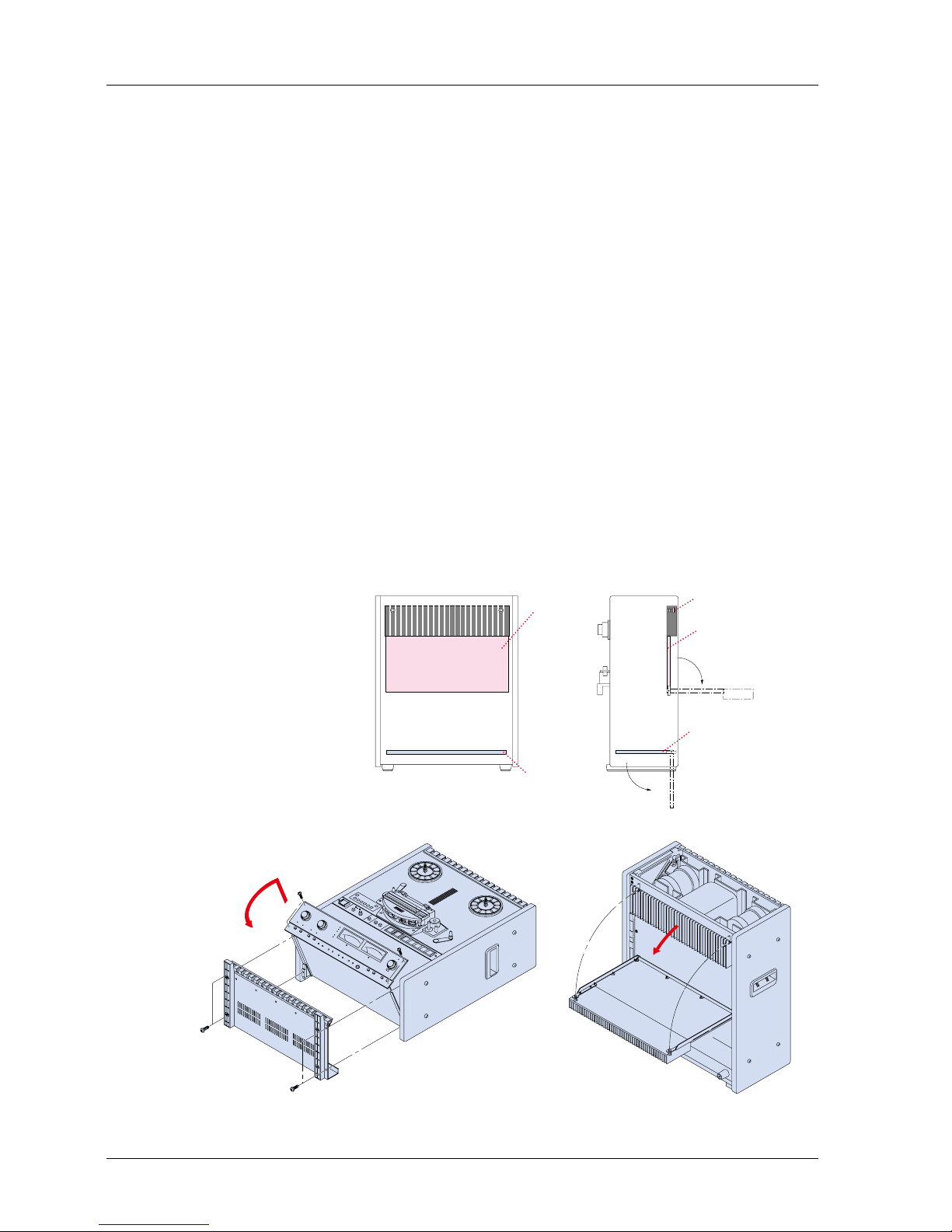
2.4 PCB Assembly Location
2.4.1 MX-5050BIII
The PCB Assemblies are located as shown in Figure 2-5. The CONTROL PCB Assembly
is accessed by removing the rear panel (refer to Figure 2-9). The CONTROL PCB can be
rotated to adjust parts on the COMP side. To access the REC/REP AMP PCB Assembly,
the AMP section of the MX-5050BIII must be turned face up. The rotation of the AMP
section is performed as follows.
AMP Section Rotation (Refer to Figure 2-6)
1. Turn off the machine. Place the machine so that the transport faces upward.
2. Remove the four screws holding the Bottom Cover. Remove the Bottom
Cover from the machine.
3. Remove the four screws holding the AMP section. While lifting the
AMP section slightly, rotate it to a horizontal position.
CONTROL PCB Assembly Rotation (Refer to Figure 2-7)
1. Turn off the machine. Place the machine in the upright position.
2. Remove the Foot and Deck Stand from the Rear Cover.
3. Remove the Rear Cover by removing the screws holding it in place.
4. Loosen the two screws holding the Heat sink. Rotate the CONTROL PCB
Assembly on its side.
5. The Side Boards may need to be removed to access some controls on the
CONTROL PCB Assembly.
CONTROL PCB
REC/REP PCB
Screw
CONTROL PCB
REC/REP PCB
Figure 2-5 PCB Assembly Location (BIII)
Figure 2-6 AMP Section Rotation Figure 2-7 CONTROL PCB Assembly Rotation
MX-5050mkIV-2/BIII-2 Operation and Maintenance Manual
8 1999-02

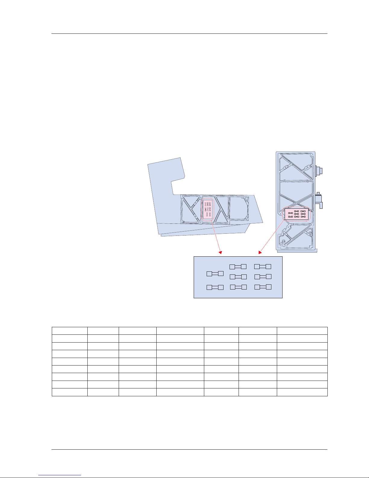
2.4.2 MX-5050MKIV-2
The AMP section of the MKIV-2 is adjusted after removing the Top Panel.
Accessing the AMP Section
1. Turn off the machine. Remove the Top Panel (for MKIV-2).
2. Adjust the PCB Assemblies (REC/REP AMP PCB Assembly) located inside
the AMP section.
CONTROL PCB Assembly Rotation
Follow the steps below when adjusting the CONTROL PCB Assembly and internal parts of
the MKIV-2.
1. Turn off the machine. Lay the machine on its side.
2. Remove the Bottom Panel by removing the screws holding it.
3. Loosen the two screws holding the Heat Sink on the Control PCB Assembly.
Rotate the CONTROL PCB Assembly.
4. Depending on the parts to be adjusted, the side panel may also need to be
removed.
CONTROL PCB
Screw
REC/REP
PCB
REC/REP
PCB
CONTROL
PCB
Figure 2-8 PCB Assembly Location
Figure 2-9 CONTROL PCB Assembly Rotation (MKIV-2)
MX-5050mkIV-2/BIII-2 Operation and Maintenance Manual
1999-02 9

2.5 Power Connection
Confirm that the power voltage marked on the rear panel corresponds with the line voltage
being used.
Turning on the machine
For power connection, use the included Power Cable. Connect the Power Cable plug to
the power connector located at the rear of the machine. Make sure that the machine is
turned off before connecting the other end of the power cable to the AC line outlet. The
machine is now ready to be turned on.
Pressing the upper portion of the POWER Switch applies power to the machine. After
power is applied to the machine, the VU meters, tape timer digits, and the indicator
above the STOP button will illuminate. The Tape Timer will show the selected tape speed
for several seconds after the machine is turned on, and then will change to tape time
indication.
Turning on the machine while pressing the STOP button will cause the ROM version of the
CONTROL PCB Assembly to be displayed.
AC Voltage Connector Replacement
When the AC Line Voltage is different from the factory setting, the Line Voltage connector
should be changed to the proper one. In this case, contact Otari or nearest Otari dealer
and order the proper Line Voltage connector. The Line Voltage connector (white) is located
beside the Supply Reel Motor. First remove the rear panel and replace it. The following
figure describes the wiring of the connectors.
AC
Hot GND AC
Neutral
Figure 2-10 Power Connection
100VAC
Brown
1-9
4-12
7-8
10-11
1-3
4-6
7-8
10-11
200VAC
Yellow
110VAC
Red
117VAC
Orange
220VAC
Green
240VAC
Blue
1-9
8-12
10-11
1-3
6-8
10-11
1-2
4-5
7-8
10-11
1-2
5-8
10-11
Figure 2-11 AC Line Voltage Connector
MX-5050mkIV-2/BIII-2 Operation and Maintenance Manual
10 1999-02
2.6 Fuse Replacement
If a fuse is blown, first check the cause of the blown fuse, then replace the fuse with a new
one as follows.
CAUTION! For continued protection against fire hazard, replace only with the
same type of fuse. Before replacing a fuse, disconnect the power cable from the
AC line.
Replacement of the Main Fuses
1. Remove the left side panel by removing the screws holding it.
2. Referring to the Figure 2-12, find the fuse location.
3. Locate the blown out fuse(s).
4. Replace the blown out fuse(s) with a new one(s).
F1
100 - 120 V 2A
200 - 240 V 1A
F2
REEL MOTOR
-18V
F3
+18V
F4
+5V
F5
+24V
F6
CAP. MOT
F7
VU LAMP
F8
2A
2A
2A
3A
4A
5A
1A
COMP SIDE
!
AC LIVE
PB-7VCA
Figure 2-12 Fuse Location
Fuse Specifications
Number Current Voltage Size Carry Otari No. Used For
F1 2A 125V 5.2 x 20mm 110% FH9-030 Power Supply
F2 2A 125V 5.2 x 20mm 110% FH7F020 Reel Motor
F3 2A 125V 5.2 x 20mm 110% FH9-030 -18V (Slow Blow)
F4 2A 125V 5.2 x 20mm 110% FH9-030 +18V (Slow Blow)
F5 3A 125V 5.2 x 20mm 110% FH7F030 +5V
F6 4A 125V 5.2 x 20mm 110% FH7F040 +24V
F7 5A 125V 5.2 x 20mm 110% FH7F050 Capstan Motor
F8 1A 125V 5.2 x 20mm 110% FH7F010 VU Lamp
MX-5050mkIV-2/BIII-2 Operation and Maintenance Manual
1999-02 11

2.7 Speed Conversion (BIII)
Normally, the MX-5050BIII-2 is shipped from the factory with set at High Speed (15/7.5 ips).
If you want to change this to Low Speed (7.5/3.75 ips), follow the steps below.
1. Remove the bottom panel to access the CONTROL PCB. Rotate the
CONTROL PCB.
2. The Speed Version Select SW1-1 is located on the CONTROL PCB. Change
the switch position to the LOW position. (☞§2.3.)
3. Replace the bottom panel on the machine.
4. Make all necessary adjustments (Reproduce EQ, SRL, Bias Record EQ,
Record Level) referring to the corresponding explanation in Section 7.
NOTE: The MX-5050MKIV-2 cannot be changed to Low Speed.
2.8 Equalization Change
The Equalization type is set to the customer’s specifications at the factory. The setting can
be changed between NAB and IEC by sliding the EQUALIZER switch on the rear panel (☞
§2.3). If the setting is changed, equalizer adjustments (§§7.3.3 and 7.4.5) must be made.
MX-5050mkIV-2/BIII-2 Operation and Maintenance Manual
12 1999-02

3. Controls and Indicators
3.1 Tape Transport
SET
ZERO 1 2 3 REPEAT CLR
TIME-IPS-%
SEARCH
H M S
H
L
TAPE SPEED
EDIT
ON
OFF
SPEED MODE
EXT FIX VARI
PITCH CONTROL
POWER
DOWN UP
SPEED REEL SIZE
S
L
S
L
L
H
SUP T.UP
CUE
5
1
4
3
2
6
8
7
Figure 3-1 Tape Transport
[1] Supply Reel Table
[2] Take-up Reel Table The Reel Tables are supplied with reel clamps for 5" or 7" reels. For 10.5 inch NAB reels,
use the supplied reel adapter.
[3] Tension Arm The Supply Tension Arm helps correct tape tension fluctuations due to changes in tape
pack diameter or irregularities in tape pack.
[4] Tacho Roller The Tacho Roller is turned by tape motion and generates tacho pulses which are used for
the calculation of tape time and recognition of the tape direction.
[5] Splicing Block When editing a tape, the tape is cut or spliced on this block.
[6] Pinch Roller The tape is driven by the rotation of the Capstan Shaft against the Pinch Roller.
[7] Capstan Shaft The Capstan Shaft is directly driven by a DC servo motor which is controlled by a quartz
crystal reference in a phase-locked-loop circuit.
[8] Tension Arm with Safety Switch The take-up tension arm is provided with a safety switch which stops the transport when
the tape becomes unthreaded from the reel or when too much slack develops in the tape
path.
MX-5050mkIV-2/BIII-2 Operation and Maintenance Manual
1999-02 13

3.2 Transport Control Panel
EDIT
ON
OFF
SPEED MODE
EXT FIX VARI
PITCH CONTROL
POWER
DOWN UP
SPEED
L
H
CUE
SET
ZERO 1 2 3 REPEAT CLR
TIME-IPS-%
SEARCH
H M S
H
L
TAPE SPEED
SET
ZERO 1 2 3 REPEAT CLR
TIME·IPS·%
SEARCH
H M S
H
L
TAPE SPEED
REEL SIZE
S
L
S
L
SUP T.UP
1 11 10 12 13 15 16 17 18 19 20 21
3 542
76 8 9
14
Figure 3-2 Transport Control Panel
[1] POWER Switch Pressing the upper portion of the Switch turns on the machine.
[2] Tape Time Display This 6-digit display shows the tape time in Hours, Minutes, and Seconds; the tape speed in
ips (inches per second); or the tape speed as a percentage change from the selected play
speed, as set by the TIME·IPS·% Button [5].
[3] SET Button Pressing this button initiates Set mode, in a desired value can be entered by using the
SEARCH keys. There are two Set modes:
A. Cue Point Set mode: Refer to §4.5.1
B. Vari Speed Set mode: Refer to §4.4.6
[4] Tape Speed Indicator This LED indicates the selected speed.
Hi Version Low Version (BIII-2)
Hi: 15 ips- Hi: 7.5 ips
Low: 7.5 ips Low: 3.75 ips
[5] TIME·IPS·% Button Pressing this button causes the Tape Time display to show, in turn, the current tape time,
the currently selected tape speed in ips, or the percentage of change from the currently
selected tape speed.
Tape Time ➔Tape Speed (ips) ➔Speed Change (%) ➔Tape Time ➔···
When the display is showing Tape Speed, “iP” appears in the rightmost column. Similarly,
when in Speed Change is being displayed, “P” appears in the rightmost column.
[6] SEARCH ZERO Button Pressing this key places the MX-5050 into Search Zero mode. In Search Zero mode the
tape is moved at Fast Wind speed to the location of 00:00:00 and is then stopped.
[7] SEARCH 1, 2, 3 Buttons Pressing one of the illuminated SEARCH keys moves the tape to the location stored in that
SEARCH key and stops.
Storing a Cue point: Refer to §4.5.1
Search Operation: Refer to §4.5.2
Clearing a Cue point: Refer to CLR key
[8] REPEAT Button Pressing REPEAT, then pressing two SEARCH keys, then pressing PLAY enters the
machine into Repeat mode. In Repeat mode, the machine repeatedly plays back the tape
between two selected points. Refer to §4.5.6. for details on Repeat mode.
MX-5050mkIV-2/BIII-2 Operation and Maintenance Manual
14 1999-02

[9] CLR Button Pressing CLR together with the one of the following keys works as follows.
CLR + SET: Exits Set mode
CLR + TIME·IPS·%: Tape Timer Display resets to zero
CLR + SEARCH 1-3: Clears Cue Point Memory
CLR + REPEAT: Exits Repeat mode
[10] Speed Mode Select Button This button selects the tape speed for Record and Play modes. Pressing this button
changes the Speed mode as follows.
FIX mode: The Capstan Motor speed is controlled by the internal crystal oscillator. The
speed setting (HI or LO) is selected by the Speed Select button.
VARI mode: Tape speed is changed by ±20% of the nominal tape speed with the Pitch
Control knob.
EXT mode: Tape Speed is controlled by the external speed reference signal conveyed
through the PARALLEL/O connector. When using a synchronizer or resolver, set the
machine to this mode.
NOTE: When the Speed Mode switch is set to the EXT position, the Tape Time display
always shows tape time.
[11] Speed Mode Indicator These indicators illuminate to show the speed mode selected with the Speed Mode Select
Button.
[12] Pitch Control Knob When the Speed Control mode is set to the VARI mode, the Pitch Control knob changes
the tape speed in Record and Play modes. The tape speed is variable over a range of ±
20% of the selected FIX speed in 0.01 % steps.
[13] Tape Speed Select Button (HI/LO) This button selects the speed setting of the machine. The following combinations are
available. The speed version is set with SW1 on the CONTROL PCB.
Machine Type HI LO
Hi Version Machine 15ips 7.5 ips
Low Version Machine 7.5ips 3.75 ips
[14] Reel Size Change Switch This switch sets the reel tension corresponding to the selected reel size. When using a
10.5" NAB Reel, set this switch to the “L” position. When using a reel smaller than 10.5",
set the switch to the “S” position.
[15] CUE Button Pressing this button during Fast Wind modes initiates Cue mode, in which the tape lifters
retract allowing the tape to be in contact with the Reproduce head for audio monitoring at
fast wind speed. There are two ways to enter Cue mode: tapping CUE or holding CUE
down. For details, refer to §4.2.1.
[16] EDIT Button Pressing this button while in Stop mode causes the MX-5050 to enter Edit Ready mode, in
which the take-up motor is turned off and the safety switch for the Take-up tension Arm is
deactivated. Pressing PLAY in Edit Ready mode, or pressing EDIT in Play mode, causes
the MX-5050 to enter Dump Edit mode, in which the Take-up reel does not rotate causing
tape to be “dumped” from the transport.
[17] RECORD Button When any channel is in Record Ready mode, pressing RECORD and PLAY simultaneously
enters Record mode. Unless the READY/SAFE switch is placed at the READY position,
actual recording will not take place. For Punch In/Out Operation, refer to §4.4.2.
[18] PLAY Button Pressing PLAY when the transport is in Stop mode enters the tape into Play mode, in which
the tape is reproduced at the currently selected tape speed. Pressing PLAY with RECORD
enters the transport into Record mode.
[19] STOP Button Pressing STOP when the transport is in Record, Play, Dump Edit, Fast Forward or Rewind
mode causes the tape motion to stop.
[20] RWD Button Pressing RWD places the transport into Rewind mode, in which the tape moves from the
Take-up reel to the Supply reel at Fast Wind speed.
[21] F.FWD Button Pressing F.FWD places the transport into Fast Forward mode, in which the tape moves
from the Supply reel to the Take-up reel at Fast Wind speed.
MX-5050mkIV-2/BIII-2 Operation and Maintenance Manual
1999-02 15

3.3 Head Assembly
55 5
4 1 2 3
Figure 3-3 Head Assembly
[1] Erase Head The Erase Head is made of ferrite. The track width is 2 mm for the MKIV-2 and BIII-2, 2.75
mm for the MKIV-2E and BIII-2E, and 6.3 mm for the BIII-F.
[2] Record Head The Record Head is made of Hard Permalloy. The track width is 2 mm for the MKIV-2 and
BIII-2, 2.75 mm for the MKIV2-E and BIII2-E, and 6.3 mm for the BIII-F.
[3] Reproduce Head The Reproduce Head is made of Hard Permalloy. The track width is 2 mm for the MKIV-2
and BIII-2, 2.75 mm for the MKIV2-E and BIII2-E, and 6.3 mm for the BIII-F.
[4] Dummy Head (BQIII)
[5] Head Guides These guides regulate the tape movement across the heads.
MX-5050mkIV-2/BIII-2 Operation and Maintenance Manual
16 1999-02

3.4 Amplifier Panel
20 10 63101
3
2
VU
PEAK
+-
20 10 63101
3
2
VU
PEAK
+-
RECORD SEL-REP RECORD BIAS CH1-RECORD EQ-CH2 RECORD LEVEL PHONES TEST OSC CH1-MONITOR-CH2
CH1 CH2 CH1 CH2 CH1 CH2 CH1 CH2
HIGH LOW HIGH LOW 1KHz 10KHz TAPESOURCE
LINE MIC LINE MIC
CH 1 CH 2INPUT
CH1 CH2
OUTPUT SRL
SRL
HIGH
MID
LOW
NAB
IEC
EQUALIZATION
REF FLUX
2 31
5
6
789141510111213
Figure 3-4 Amplifier Panel
[1] Input Level Knobs The outer knob adjusts the line input signal level. The inner knob adjust the microphone
input signal level.
[2] VU Meters The VU meters indicate the record and reproduce levels of the associated channels. The
VU meters illuminate when the machine is turned on.
[3] Peak Level Indicators (LED) Each VU meter has a PEAK level indicator which illuminates when the signal reaches a level
equivalent to 1040 nWb/m.
[4] SRL Indicator This illuminates when the SRL button is pressed.
[5] Output Level Knob The outer knob adjusts CH1 output signal level. The inner knob adjusts CH2 output signal
level.
[6] SRL Switch This switch selects the Standard Reference Level (SRL) of the output level. When this
switch is pressed, the output level is set to the SRL (factory setting: +4 dB).
[7] Monitor Button This button selects the monitor signal source. When this button is set to SOURCE position,
all the OUTPUT connectors and VU Meters receive the signal present at the INPUT
connector. When this button is set to TAPE position, the signal reproduced with the Repro
Head is output.
[8] Test Oscillator Buttons Pressing one of these buttons activates the test oscillator. The selectable oscillator
frequencies are 1 kHz and 10 kHz.
[9] Monitor Phone Jack This is the monitoring Head Phone Jack. Load Impedance is 8
[10] SEL·REP Mode Button If the Monitor button is set to TAPE position and the SEL·REP Mode button is pressed, all
the OUTPUT connectors and VU Meters receive signals reproduced by the Record head.
[11] SEL·REP Indicator This indicator illuminates when the SEL·REP mode is selected.
[12] RECORD READY Buttons When these buttons are pressed, the machine enters into Ready mode. In Ready mode,
the machine enters Record mode when the RECORD and PLAY buttons are pressed. If
these buttons have not been depressed, the machine is set to SAFE. In Safe mode, the
machine cannot enter Record mode even if the RECORD and PLAY buttons are pressed.
[13] RECORD Mode Indicator This indicator illuminates when the machine is set to Record Ready mode.
[14] EQ indicator This indicator illuminates to show the selected EQ setting.
[15] REF FLUX indicator This indicator illuminates to show the selected Reference Flux Level.
MX-5050mkIV-2/BIII-2 Operation and Maintenance Manual
1999-02 17

3.5 Audio Connector Panel
PARALLEL I/O
GROUND POWER
LINE INPUTLINE OUTPUT
CH 2CH 1 CH 1CH 2CH 1
CH 2
MIC INPUT
LOW MID HIGH
IEC NAB
LOW HIGH
OUTPUT LEVEL EQUALIZATION
REF FLUX MIC ATTENUATOR
OdB -2OdB OFF
8 9 10 1 2 3
7 6 5 4
Figure 3-5 Audio Connector Panel (BIII)
POWER GROUND
PARALLEL I/O
LINE INPUTLINE OUTPUT
CH 2CH 1 CH 1CH 2CH 1
CH 2
MIC INPUT
MIC ATTENUATOR
OdB-2OdB OFF
REF FLUX
LOW MID HIGH
EQUALIZATION
IEC NAB
OUTPUT LEVEL
LOW HIGH
1 2 3
4567
9 10 8
Figure 3-6 Audio Connector Panel (MKIV-2)
MX-5050mkIV-2/BIII-2 Operation and Maintenance Manual
18 1999-02
This manual suits for next models
4
Table of contents
Other OTARI VCR System manuals


