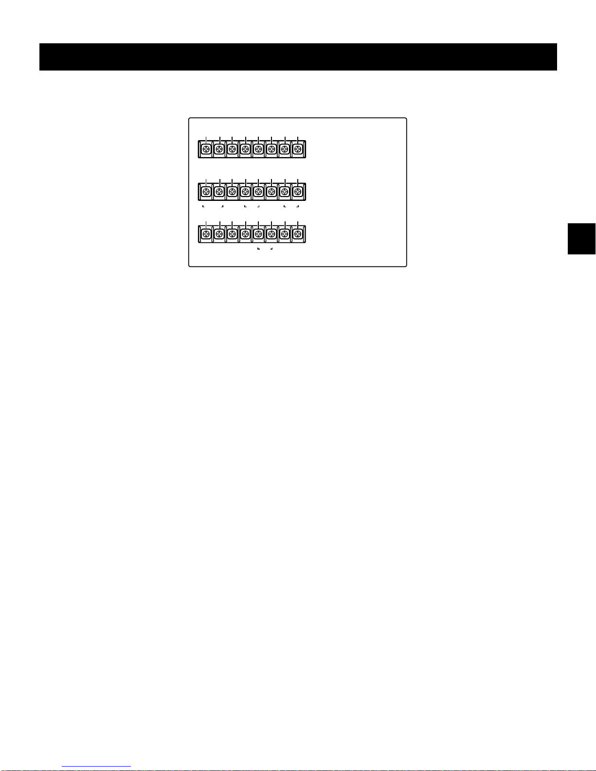
Sanyo DTL-4800 User manual

INSTRUCTION MANUAL DTL-4800
Real Time Video Cassette Recorder English
Magnétoscope en temps réel Français
Videograbador en tiempo real Español
Please read this manual and accompanying “IMPORTANT SAFETY INSTRUCTIONS” sheet carefully before connecting your
VCR and operating it for the first time.
Be sure to read carefully and follow all the PRECAUTIONS on page 1 and 2.
Keep the manual in a safe place for future reference.
DIGITAL
RD2QD/NA (DTL-4800 GB) Tue.Aug., 08/2000

PRECAUTIONS
CAUTION
RISK OF ELECTRIC SHOCK
DO NOT OPEN
CAUTION:TO REDUCE THE RISK OF ELECTRIC SHOCK,
DO NOT REMOVE COVER (OR BACK).
NO USER-SERVICEABLE PARTS INSIDE.
REFER SERVICING TO QUALIFIED SERVICE PERSONNEL.
The lightning flash with arrowhead symbol, within an
equilateral triangle, is intended to alert the user to the
presence of uninsulated “dangerous voltage” within the
product’s enclosure that may be of sufficient magnitude
to constitute a risk of electric shock to persons.
The exclamation point within an equilateral triangle is
intended to alert the user to the presence of important
operating and maintenance (servicing) instructions in
the literature accompanying the product.
WARNING: To reduce the risk of fire or electric
shock, do not expose this appliance to rain or
other moisture.
CAUTION: Changes or modifications not expressly
approved by the manufacturer may void the user’s
authority to operate this equipment.
For the customers in Canada
This class B digital apparatus complies with Canadian
ICES-003.
This equipment has been tested and found to comply
with the limits for a Class B digital device, pursuant to
part 15 of the FCC Rules. These limits are designed to
provide reasonable protection against harmful
interference in a residential installation. This
equipment generated, uses and can radiate radio
frequency energy and, if not installed and used in
accordance with the instructions, may cause harmful
interference to radio communications. However, there
is no guarantee that interference will not occur in a
particular installation. If this equipment does cause
harmful interference radio or television reception,
which can be determined by turning the equipment off
and on, the user is encouraged to try to correct the
interference by one or more of the following measures:
œReorient or relocate the receiving antenna.
œIncrease the separation between the equipment
and receiver.
œConnect the equipment into an outlet on a circuit
different from that to which the receiver is
connected.
œConsult the dealer or an experienced radio/TV
technician for help.
Model Number : DTL-4800
Trade Name : SANYO
Responsible party : SANYO FISHER COMPANY
Address : 21605 Plummer Street,
Chatsworth, California 91311
Telephone No. : (818) 998-7322
œThis device complies with Part 15 of the FCC Rules.
Operation is subject to the following two conditions:
(1) this device may not cause harmful interference,
and
(2) this device must accept any interference
received, including interference that may
cause undesired operation.
Declaration of Conformity
RD2QD/NA (DTL-4800 GB) Tue. Aug., 08/2000
English 1

PRECAUTIONS
Location
For safe operation and satisfactory performance of your
VCR, keep the following in mind when selecting a place
for its installation:
œShield it from direct sunlight and keep it away from
sources of intense heat.
œAvoid dusty or humid places.
œAvoid places with insufficient ventilation for proper heat
dissipation. Do not block the ventilation holes of the
VCR. Do not place the unit on a carpet because this
will block the ventilation holes.
œInstall the VCR in a horizontal position only.
œAvoid locations subject to strong vibrations.
œAvoid moving the VCR between cold and hot locations
(see “Moisture Condensation Problems”, this page).
œDo not place the VCR directly on top of the TV, as this
may cause playback or recording problems.
Avoiding Electrical Shock and Fire
œDo not handle the power cord with wet hands.
œDo not pull on the power cord when disconnecting it
from an AC wall outlet. Grasp it by the plug.
œIf any liquid is spilled on the VCR, unplug the power
cord immediately and have the unit inspected at a
factory-authorized service center.
œDo not place anything directly on top of this VCR.
Moisture Condensation Problems
Cause:
When the VCR is first installed, moved from a cold area to
a warm area or placed in a location with high humidity,
dew (moisture) may form in the unit. The Dew indicator
(4) blinks. If you operate the VCR with dew inside,
damage may result.
Prevention:
1Make all necessary connections.
2Plug the power cord into a 120 V AC wall outlet.
3Do not operate the VCR for approximately 2 hours.
When the VCR reaches room temperature, the Dew
indicator (4) will turn off and the VCR will be ready to
operation.
About this VCR operation (block
recording)
This VCR is equipped with a memory function that, while
recording (or playback), will first store the pictures in the
internal memory before it actually records them to tape (or
outputs them to the screen). This function will prevent
damage to the tape and video heads. Therefore, during
recording/playback, the tape counter and the tape
mechanism will start and stop repeatedly. This is normal
and does not indicate a mechanical problem.
During recording:
The images from the camera or other signal input source
are first stored to memory, then when the memory
reaches its capacity, the images are recorded onto the
tape.
During playback:
The images recorded on the tape are first read into the
memory, then when the memory reaches its capacity, the
images are output to the monitor screen.
Video Cassette Tapes
Use only video cassette tapes bearing the S-VHS logo.
This VCR was primarily designed for use with
ST-180XZES cassette tapes, for optimal performance
only use ST-180XZES S-VHS videocassettes.
ST-180XZES cassette tapes are available at any dealer
where this unit is sold.
RD2QD/NA (DTL-4800 GB) Tue. Aug., 08/2000
2English

CONTENTS
PRECAUTIONS . . . . . . . . . . . . . . . . . . . . . . . . . . . . . . . . 1
FEATURES. . . . . . . . . . . . . . . . . . . . . . . . . . . . . . . . . . . . 3
ACCESSORIES . . . . . . . . . . . . . . . . . . . . . . . . . . . . . . . . 3
LOCATIONS OF CONTROLS AND INDICATORS . . . . . 4
CONNECTIONS. . . . . . . . . . . . . . . . . . . . . . . . . . . . . . . . 9
ON-SCREEN MENUS . . . . . . . . . . . . . . . . . . . . . . . . . . 11
SETTING THE LANGUAGE AND CLOCK. . . . . . . . . . . 13
CHANGING THE ON-SCREEN DISPLAY. . . . . . . . . . . 15
VIDEO CASSETTE TAPES . . . . . . . . . . . . . . . . . . . . . . 16
TAPE MANAGEMENT FUNCTION . . . . . . . . . . . . . . . . 18
NORMAL RECORDING . . . . . . . . . . . . . . . . . . . . . . . . . 21
AUTOREPEAT RECORDING . . . . . . . . . . . . . . . . . . . . 26
ALARM RECORDING . . . . . . . . . . . . . . . . . . . . . . . . . . 27
PROGRAM TIMER RECORDING . . . . . . . . . . . . . . . . . 31
RECORDING USING AN EXTERNAL TIMER INPUT. . 35
TRIGGER SHOT RECORDING . . . . . . . . . . . . . . . . . . . 36
SERIES RECORDING . . . . . . . . . . . . . . . . . . . . . . . . . . 37
PLAYBACK. . . . . . . . . . . . . . . . . . . . . . . . . . . . . . . . . . . 39
TAPE COUNTER . . . . . . . . . . . . . . . . . . . . . . . . . . . . . . 40
DAY/TIME SEARCH. . . . . . . . . . . . . . . . . . . . . . . . . . . . 41
SETTING THE SECURITY LOCK . . . . . . . . . . . . . . . . . 42
SETTING THE BUZZER . . . . . . . . . . . . . . . . . . . . . . . . 43
CLOCK ADJUSTMENT . . . . . . . . . . . . . . . . . . . . . . . . . 44
SETTING THE CASSETTE EJECT MODE . . . . . . . . . . 45
SETUP FOR RS-232C OR RS-485 USE . . . . . . . . . . . . 46
CHECKING POWER FAILURE, FAILURE DUE TO
CONDENSATION AND USAGE DURATION . . . . . 48
OUTPUT TERMINALS . . . . . . . . . . . . . . . . . . . . . . . . . . 49
MAINTENANCE . . . . . . . . . . . . . . . . . . . . . . . . . . . . . . . 51
TROUBLESHOOTING GUIDE. . . . . . . . . . . . . . . . . . . . 53
SPECIFICATIONS . . . . . . . . . . . . . . . . . . . . . . . . . . . . . 54
WARRANTY. . . . . . . . . . . . . . . . . . . . . . . . . . . . . . . . . . 55
FEATURES
œDigital recording/playback
œ520 lines horizontal resolution
œPre-Alarm and Post-Alarm recording function
œIn 12, 24, 48, 72-hour modes audio recording is
available
œCan be controlled through an RS-232C or RS-485
connection
œSwitchable Time-Date on-screen display
œTape management function
œMultiple menu language (English/French/Spanish)
œAutomatic Daylight Saving Time adjustment
œAlarm recording function
œTimer recording function
œAutorepeat recording function
œSeries recording function
œTrigger shot recording function
œAlarm search and Alarm scan function
œDay/Time search function
œClog detection
œThread check
œForward/reverse field advance
œForward/reverse digital view
œForward/reverse search
œSecurity lock
ACCESSORIES
Power cord
Ni-Cd Battery (battery pack)
Video cassette tape (ST-180XZES)
RD2QD/NA (DTL-4800 GB) Tue. Aug., 08/2000
English 3

LOCATIONS OF CONTROLS AND INDICATORS
Front Panel
1POWER indicator
2REPEAT (autorepeat recording) indicator
3Digital display panel
4Cassette loading slot
5REW (rewind) button
6PLAY button
7STILL/PAUSE button
8FF (fast forward) button
9Ni-Cd battery compartment
FSEARCH (FRAME/FIELD) button
GEJECT button
HMENU EXIT button
IREC/PLAY SPEED, DATA l, j(decrease, increase
recording/playback speed mode, to select numbers or
switch settings in reverse order, in order) button.
JSHIFT ], \, +, *(selection, display position down,
up, left, right) button
KMENU button
LCOUNTER MEMORY button
MTRACKING –, +button
NCOUNTER RESET button
OTIMER button
PON SCREEN switch
QALL RESET button
RMENU RESET button
SSTOP button
TREC (record) button
UFront door
POWER
b
ON SCREEN TIMER
COUNTER
RESET MEMORY REC/PLAY
SPEED
DATA
MEMU MENU
EXIT
TRACKING
–
V.STILL
+
OFF
ON
REPEAT
a
REC
1 2 3 4 56 7 8 9
T S RQU FGHKLNOP M J I
]«»
\j
l
f
REW
c
PLAY
h
STILL/PAUSE
e
FF
SEARCH
i
EJECT
MENU RESET
ALL RESET
SHIFT
STOP
a
REC
FRAME/FIELD
RD2QD/NA (DTL-4800 GB) Tue. Aug., 08/2000
4English

LOCATIONS OF CONTROLS AND INDICATORS
Digital Display
1Operation Indicators
œThey display the actual operation mode.
Operation Mode Indicator
Record (REC)
Record pause (REC PAUSE)
Playback (PLAY)
Still image (STILL)
Fast forward (FF)
Rewind (REW)
Forward digital view
Reverse digital view
Forward search
Reverse search
Forward field advance
Reverse field advance
œClog detection indicator
Flashes when the recording quality deteriorates
due to dirty VCR heads.
2Cassette indicator
Comes on when a cassette is loaded.
Flashes during thread check function.
3Alarm indicator
Flashes when an alarm is
being recorded:
Comes on after the alarm
has been recorded:
4Power failure indicator
Comes on after a power failure.
5Mode display
œRecording/playback
speed mode
œAlarm search mode
œAlarm scan mode
œDew display
œCooling fan failure indicator
If the cooling fan does not operate properly, the
indicator will flash and the buzzer will be heard.
(Press the STOP button to stop the buzzer.)
The display will stay on until the cooling fan is
repaired. If the unit is used without first repairing
the cooling fan, that may cause damages to other
components.
œBattery failure indicator
If the battery fails, the indicator will flash and the
buzzer will be heard. (Press the STOP button to
stop the buzzer.)
The display will stay on until the battery is
replaced. If the battery is not replaced and there is
a power failure, the contents of the memory will be
lost (not recorded to the tape).
5, 6Mode display
œDay/Time search
mode
12 5
MH
OFF
MS
6789F
E
G
3 4
RD2QD/NA (DTL-4800 GB) Tue. Aug., 08/2000
English 5

LOCATIONS OF CONTROLS AND INDICATORS
6Counter display
œTime display
œCounter display
Automatic tracking display
œFlashes while automatic tracking is performed.
Mode display
œSweep out mode
Flashes while the memory contents are being
recorded onto the tape after the end of the
recording or the STOP button has been pressed to
stop recording.
œBack up mode
Flashes (up to 20 seconds) when the power is
restored to the unit, if the power has been
interrupted during recording.
NOTES:
œWill not be displayed, if the power failure lasts
more than 20 seconds.
œMay not be displayed according to the memory
contents and power failure duration.
7OFF indicator
Comes on when the tape end has been reached after
a recording.
8Counter memory indicator
Comes on when the counter memory function is
engaged.
9Timer Recording indicator
Comes on when in timer recording stand-by mode, or
during a timer recording.
FSecurity lock indicator
Comes on when the security lock is engaged.
GExternal timer input indicator E
Comes on when recording using the EXT TIMER IN
input terminal.
HMS
OFF
M
RD2QD/NA (DTL-4800 GB) Tue. Aug., 08/2000
6English

LOCATIONS OF CONTROLS AND INDICATORS
Back Panel
1Ventilation opening
NOTE: The cooling fan is located behind this
opening, make sure it is not blocked.
2VIDEO IN (video input) jack
3VIDEO OUT (video output) jack
4S-VIDEO IN (S-VHS video input) jack
5S-VIDEO OUT (S-VHS video output) jack
6RS485 A connector (RJ11 type)
7RS485 B connector (RJ11 type)
8AUDIO IN (audio input) jack
9AUDIO OUT (audio output) jack
FMIC IN (microphone input) jack
GVarious terminals (see page 8)
HLithium Battery compartment
IREMOTE (remote control input) jack
JRS232C connector (D-sub 9-pin type)
KDIP switches
œUsed when controlling the VCR through the RS485
or the RS232C connectors.
LAC power input
VIDEO
AC IN
AUDIO MIC IN
S-VIDEO
IN OUT IN OUT IN OUT
ABRS485
RS232C
REMOTE
ADDRESS TERMINATE
EXT
TIMER IN
ALARM
RESET
IN
TRIGGER
SHOT REC
IN
TIMER
OUT WARNING
OUT TAPE
END OUT NON REC
OUT V.LOSS
OUT
SW
OUT COM
COM COM
IN OUT
CLOCK SET
485
232
ON
OFF OFF
ON
PUSH
OPEN
IN OUT
SERIES
IN OUT
ALARM
IN OUT
EJECT
L K J I H
15
96
Pin locations
(male) on the VCR
Pin locations
(female) on the VCR
1 6
NOTE:
Do not connect to
phone line.
1 2 3 4 5 76 8 9 F G
RD2QD/NA (DTL-4800 GB) Tue. Aug., 08/2000
English 7

LOCATIONS OF CONTROLS AND INDICATORS
1EXT TIMER IN (external timer input) terminal
2TIMER OUT (timer recording output) terminal
3WARNING OUT (warning output) terminal
4TAPE END OUT (tape end output) terminal
5SW OUT (switch output) terminal
6COM (common) terminal
7NON REC OUT (non recording output) terminal
8V. LOSS OUT (video loss output) terminal
9CLOCK SET IN (external clock set trigger input)
terminal
FCLOCK SET OUT (external clock set trigger output)
terminal
GCOM (common) terminal
HSERIES IN (series recording trigger input) terminal
ISERIES OUT (series recording trigger output) terminal
JCOM (common) terminal
KEJECT IN (eject trigger input) terminal
LEJECT OUT (eject trigger output) terminal
MALARM RESET IN (alarm reset input) terminal
NDo not use
OTRIGGER SHOT REC IN (trigger shot recording
trigger input) terminal
PDo not use
QALARM IN (alarm input) terminal
RALARM OUT (alarm output) terminal
SDo not use
TDo not use
12345678
9FGHIJKL
MNOPQRST
EXT
TIMER IN TIMER
OUT WARNING
OUT TAPE
END OUT SW
OUT COM NON REC
OUT V.LOSS
OUT
NOTE:
This terminal board
may be damaged by
0.49N·m (5kg·cm) or
more torque and using
φ6mm-tip or more size
screwdrivers.
IN OUT COM IN OUT COM IN OUT
EJECT
ALARM
RESET
IN
TRIGGER
SHOT REC
IN
IN OUT
SERIESCLOCK SET
ALARM
RD2QD/NA (DTL-4800 GB) Tue. Aug., 08/2000
8English

CONNECTIONS
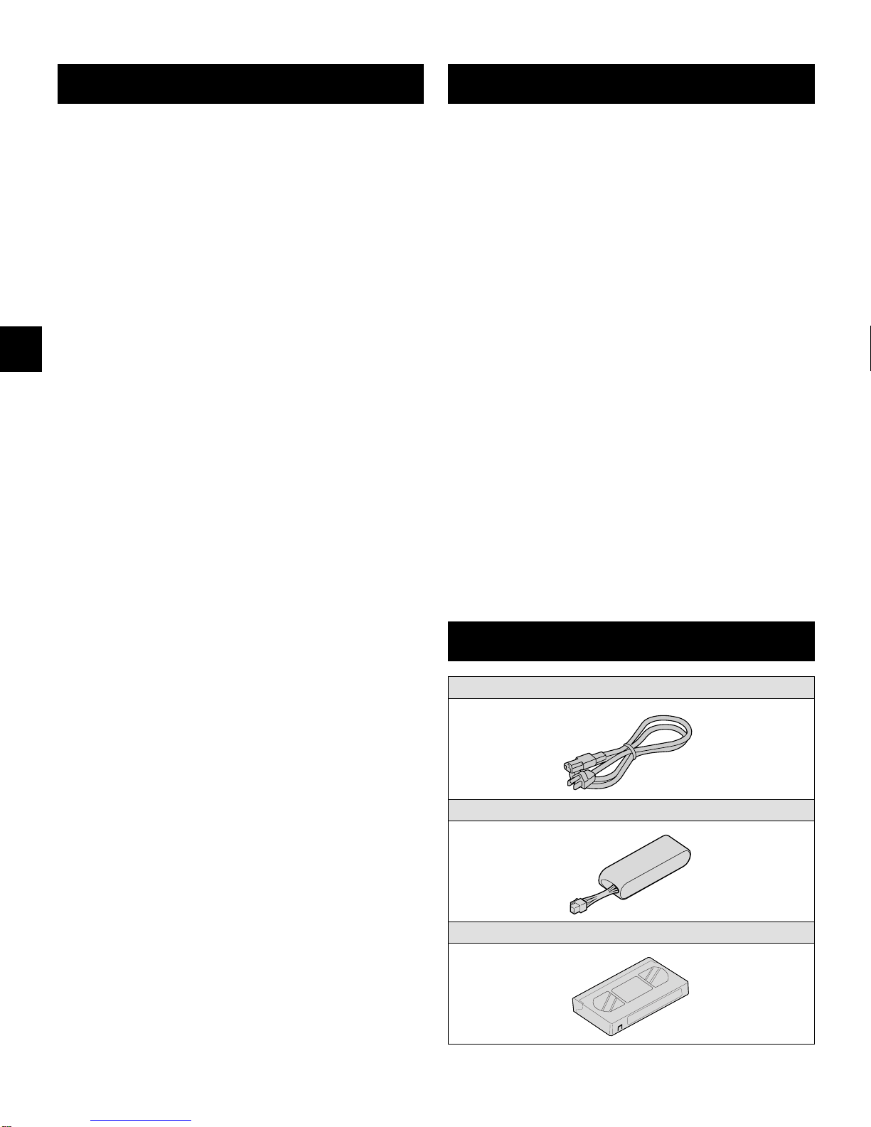
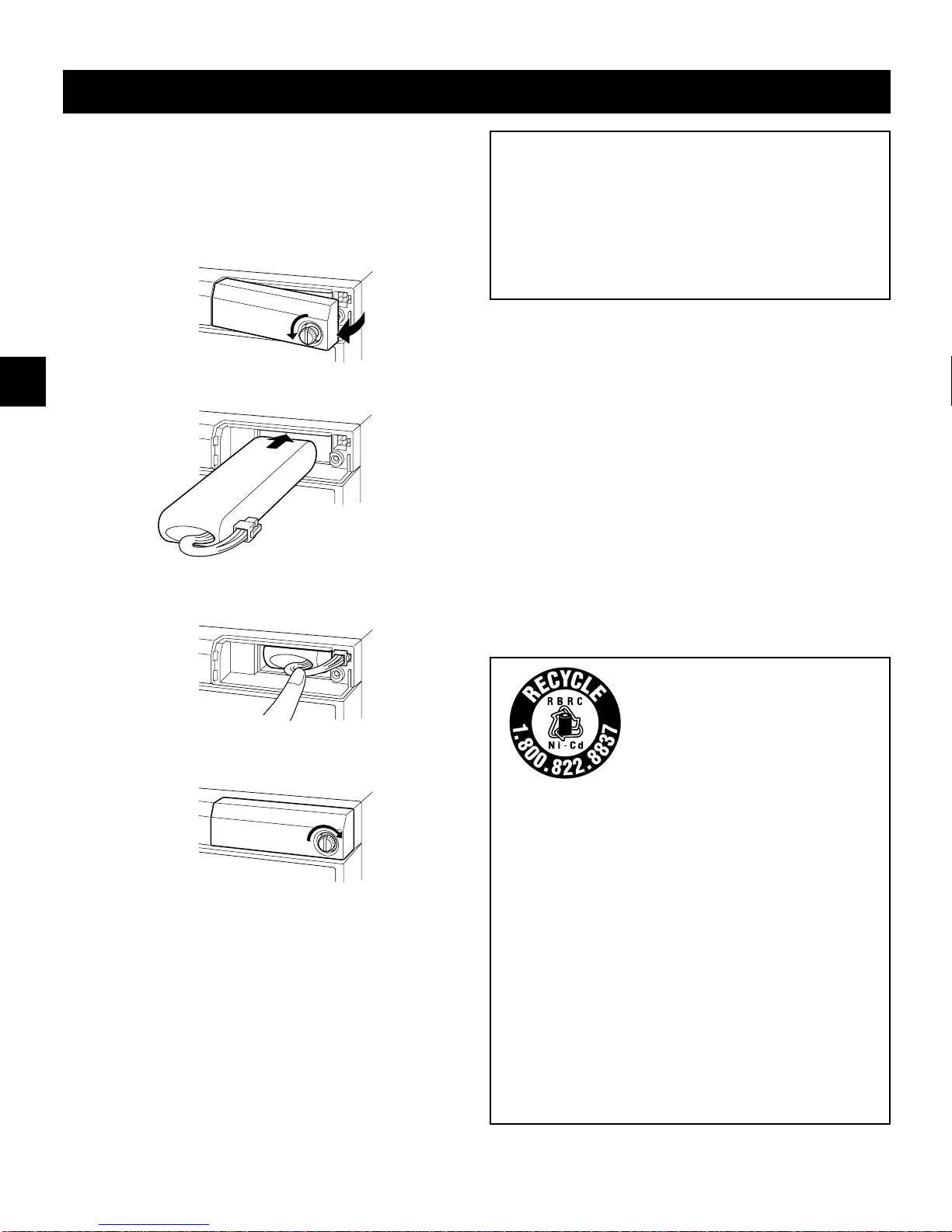
INSTALLING THE Ni-Cd BATTERY
The supplied Ni-Cd battery should be installed correctly
before using the VCR.
1Unscrew the Ni-Cd battery compartment screw until
the cover can be opened (the screw cannot be
removed from the cover).
2Insert the battery in the support with the wires facing
out.
3Checking for correct plug alignment, connect it to the
connector on the VCR, then push the wires in, out of
the way.
4Install the Ni-Cd battery compartment cover, then
tighten the screw (make sure the cover does not
pinch the wires).
Protection against power failure
In case of a power failure during recording, the Ni-Cd
battery will power the VCR until all the memory contents
are recorded onto the tape.
When the Ni-Cd battery reaches the end of its useful life,
“b” will flash on the digital display and the buzzer will be
heard.
The battery useful life may vary according to operating
conditions, but it should normally last around 2 years.
WARNING:
œDo not short-circuit the battery pack terminals, and
never try to disassemble or modify the battery pack.
œDo not throw it into a fire, as it may explode.
œDo not expose the battery to moisture.
œDo not drop or subject it to violent shock.
œDo not expose to dropping or splashing water.
CAUTION
To prevent the battery from leaking, overheating or
exploding follow the precautions below.
œDo not open or modify.
œDo not remove or cut the external tube.
œDo not submit to strong shock.
œDo not use in any other VCR model other than this one
(DTL-4800).
If the liquid gets into your eyes, you may lose your
eyesight. Do not rub your eyes, rinse your eyes
immediately with clean water, then seek medical attention.
If the batteries leak and liquid gets on your hands or
clothing it may cause injury or damages, rinse
immediately with clean water.
Do not hold by the connector or connecting wire.
IMPORTANT NOTE:
The EPA certified RBRC®Battery
Recycling Seal on the
nickel-cadmium (Ni-Cd) battery
indicates SANYO is voluntarily
participating in an industry
program to collect and recycle
these batteries at the end of their
useful life, when taken out of
service in the United States or
Canada. The RBRC program
provides a convenient alternative
to placing used Ni-Cd batteries
into the trash or the municipal
waste stream, which may be
illegal in your area. Please call
1-800-822-8837 for information
on Ni-Cd battery recycling and
disposal bans/restrictions in your
area. SANYO’s involvement in
this program is part of our
commitment to preserving our
environment and conserving our
natural resources.
RD2QD/NA (DTL-4800 GB) Tue. Aug., 08/2000
English 9

CONNECTIONS
Connect the video camera and monitor TV as shown in the figure below.
NOTE: Before making the connections, make sure the devices are disconnected from the power outlet.
VIDEO
AC IN
AUDIO MIC IN
S-VIDEO
IN OUT IN OUT IN OUT
ABRS485
RS232C
REMOTE
ADDRESS TERMINATE
EXT
TIMER IN
ALARM
RESET
IN
TRIGGER
SHOT REC
IN
TIMER
OUT WARNING
OUT TAPE
END OUT NON REC
OUT V.LOSS
OUT
SW
OUT COM
COM COM
IN OUT
CLOCK SET
485
232
ON
OFF OFF
ON
PUSH
OPEN
IN OUT
SERIES
IN OUT
ALARM
IN OUT
EJECT
To remote control
(sold separately)
Video camera
(sold separately)
Monitor TV (sold separately)
Coaxial cable
(sold separately)
To
VIDEO IN
jack
To
VIDEO
OUT
jack
From an external
audio source
Power cord
To outlet
Power Cord Installation
1Plug the supplied power cord firmly into the AC power
input AC IN ~ socket.
2Insert the plug of this power cord into a outlet.
About the memory reset
If the VCR location is changed or to cancel previous
settings, please reset the memory as described below.
To reset the memory, press the ALL RESET button.
NOTE:
œThe time and date will be reset, and the quick method
security lock will be cancelled. The (SECURITY LOCK)
menu data cannot be reset.
NOTES:
œFor more details, please refer to the manuals
accompanying all other devices. If the connections are
not made properly, it may cause a fire or damage the
equipment.
œYou can use a VA-RMN01 Remote Control Unit (sold
separately) to control remotely the VCR.
œThe grounded power cord (3 pin plug) must be
connected to a grounded power outlet.
œIf there is no video signal when the power is turned on,
“NO VIDEO” will be displayed on-screen.
œWhen both the VIDEO IN jack and S-VIDEO IN jack
are connected, the S-VIDEO IN jack will have priority.
œWhen a multiplexer is used, a connection must be
made between the SW OUT terminal on the VCR and
the SW IN terminal on the multiplexer. If the connection
is not made, depending on the recording mode a part
of the image may not be recorded.
RD2QD/NA (DTL-4800 GB) Tue. Aug., 08/2000
10 English

ON-SCREEN MENUS
Main menus
1When no menu is displayed on-screen, press the
MENU button.
ø
The (MAIN MENU 1) menu appears.
œWhen the first line “1. LANGUAGE/CLOCK SET” of
the (MAIN MENU 1) is flashing, press the SHIFT \
button or when the last line “9. TAPE
MANAGEMENT” is flashing, press the SHIFT ]
button to go to the (MAIN MENU 2).
œWhen the first line “1. RS-485 SET” of the (MAIN
MENU 2) is flashing, press the SHIFT \button or
when the last line “4. SECURITY LOCK” is
flashing, press the SHIFT ]button to go to the
(MAIN MENU 1).
œWhen a main menu is displayed, press the SHIFT ]or
\button to select a sub-menu. When the desired
sub-menu is flashing, press the MENU button to select
it.
œPress the MENU EXIT or SEARCH button to return to
the monitor screen.
MAIN MENU 1 menu
@@@@@@<MAIN@MENU@1>
1.LANGUAGE/CLOCK@SET
2.DISPLAY@SET
3.BUZZER@SET
4.VARIOUS@SET@1
5.VARIOUS@SET@2
6.RECORD@SET
7.TIMER@SET
8.HOLIDAY@SET
9.TAPE@MANAGEMENT
TO@MAIN@MENU@2
MAIN MENU 2 menu
@@@@@@<MAIN@MENU@2>
1.RS-485@SET
2.ALARM@LOG
3.POWER/DEW/USED@TIME
4.SECURITY@LOCK
TO@MAIN@MENU@1
NOTE:
œLine 1. of the (MAIN MENU 2) menu will change
according to the DIP switch 9 setting. When down “1.
RS-232C SET” is displayed and when up “1. RS-485
SET” is displayed.
Sub-menus
1From within one of the main menus, press the SHIFT
]or \button to select one of the sub-menus, then
press the MENU button.
ø
The selected sub-menu appears.
œTo enter or modify settings within a sub-menu,
press the SHIFT ], \, +or *button to move the
selection to the desired setting, then press the
DATA l(or j) button to enter or modify the
setting.
œPress the MENU button to save any setting made and
switch menu screens.
œPress the MENU EXIT or SEARCH button to save the
settings and return to the monitor screen.
Reference pages are shown in square brackets.
LANGUAGE/CLOCK SET menu
@@<LANGUAGE/CLOCK@SET>
*LANGUAGE-LANGUE-IDIOMA [13]
@@@ENGLISH
*CLOCK@SET [13]
@01-01-2000@SAT@00:00:00
*DAYLIGHT@SET@@@@@NO@USE [14]
@@@@@@@@WEEK@MONTH@TIME
@ON@@@1ST-SUN@@04@02:00
@OFF@@LST-SUN@@10@02:00
DISPLAY SET menu
@@@@<DISPLAY@SET> [15]
@DATE@@@@@@@@@@@@@Y
@TIME@@@@@@@@@@@@@Y
@ALARM@COUNT@@@@@@Y
@SPEED@@@@@@@@@@@@Y
@ALARM@NOTATION@@@Y
BUZZER SET menu
@@@@<BUZZER@SET> [43]
*BUZZER@@@@@@SET@UP
@@ALARM@IN@@@@@@@@Y
@@TAPE@END@@@@@@@@Y
@@KEY@IN@@@@@@@@@@N
@@WARNING@@@@@@@@@Y
@@THREAD@CHECK@@@@Y
@@VIDEO@LOSS@@@@@@Y
@@NON@REC@@@@@@@@@Y
@@CLOG@DETECT.@@@@Y
RD2QD/NA (DTL-4800 GB) Tue. Aug., 08/2000
English 11

ON-SCREEN MENUS
VARIOUS SET 1 menu
@@@@<VARIOUS@SET@1>
*THREAD@CHECK@@@@Y [17]
*REMOTE@@@@@@@@@@EJECT [50]
*EXT@TIME@ADJ.@@@01:00 [44]
*TAPE@END@OUT@@@@PRE [49]
*EJECT@SET [45]
@@EJECT@MODE@@@@@EJECT1
@@OPERATION@@@@@@SLAVE
VARIOUS SET 2 menu
@@@@<VARIOUS@SET@2>
*TAPE@IN@MODE@@@@STOP [17]
*VIDEO@LOSS@@@@@@Y [24]
*REC@SPEED@@@@@@@N [25]
*CLOG@DETECT.@@@@Y [23]
*SERIES@REC@IN@@@N [37,38]
*MX@@@@@@@@@@@@@@SANYO [25]
RECORD SET menu
@@@@@<RECORD@SET>
*ALARM@RECORD@MODE@@Y1 [27,28]
@@SPEED@@@@@@@@@@@@@N12
@@DURATION@@@@@@@@@@20S
*PRE@ALARM@RECORD@@@OFF [30]
*POST@ALARM@RECORD@@OFF [30]
@@DURATION@@@@@@@@@@20S
*TRIGGER@SHOT@REC@@@1 [36]
*TAPE@END@MODE@@@@@@REW [24]
TIMER SET menu
@@@@@@@<TIMER@SET> [31-35]
WEEK@START@@STOP@@@SPD
SUN@@--:--@@--:--@----@N
MON@@--:--@@--:--@----@N
TUE@@--:--@@--:--@----@N
WED@@--:--@@--:--@----@N
THU@@--:--@@--:--@----@N
FRI@@--:--@@--:--@----@N
SAT@@--:--@@--:--@----@N
DLY@@--:--@@--:--@----@N
EXT@@*****@@*****@----@N
HOLIDAY SET menu
@@@@@<HOLIDAY@SET> [33]
@@1@@-----@@@11@@-----
@@2@@-----@@@12@@-----
@@3@@-----@@@13@@-----
@@4@@-----@@@14@@-----
@@5@@-----@@@15@@-----
@@6@@-----@@@16@@-----
@@7@@-----@@@17@@-----
@@8@@-----@@@18@@-----
@@9@@-----@@@19@@-----
@10@@-----@@@20@@-----
TAPE MANAGEMENT menu
@@@<TAPE@MANAGEMENT> [18-20]
*TAPE@MANAGE.@@@@N
*PROTECT@DAY@@@@@30
*REC@PASS@SET@@@@10
*GROUP@NO.@@@@@@@OFF
*OVERRIDE@@@@@@@@N
RS-485 SET (or RS-232C SET) menu
@@@<RS-485@SET> [46-48]
@DATA@SPEED@@@@@19200
@STATUS@INFO@@@@Y
@ALARM@INFO@@@@@Y
ALARM LOG menu
@@@@@@<ALARM@LOG>@@@@000 [28]
@@@@@001@-----@--:--
@@@@@002@-----@--:--
@@@@@003@-----@--:--
@@@@@004@-----@--:--
@@@@@005@-----@--:--
@@@@@006@-----@--:--
@@@@@007@-----@--:--
@@@@@008@-----@--:--
@@@@@009@-----@--:--
@@@@@010@-----@--:--
POWER/DEW/USED TIME menu
@@@@@<POWER@FAILURE> [48]
000@FAILURE@@-----@--:--
@@@@RECOVERY@-----@--:--
@@@@@@@@@@<DEW> [48]
000@FAILURE@@-----@--:--
@@@@RECOVERY@-----@--:--
@@@@@@@<USED@TIME> [48]
@@@@VIDEO@@@@@@@00000H
@@@@POWER@@@@@@@00000H
SECURITY LOCK menu
@@@<SECURITY@LOCK> [42]
*PASS@WORD@@@@@@----
*TIMER@@@@@@@@@@NO@USE
@@ON@@@@@@@@@@@@--:--
@@OFF@@@@@@@@@@@--:--
NOTES:
œWhen a menu is displayed, recording will not be
possible.
œDuring recording or playback the menus cannot be
displayed.
œTo reset the settings of a menu to their original values,
select the desired menu then press the MENU RESET
button. The (USED TIME) menu data cannot be reset.
œIf a remote control circuit is used to control the unit and
the SECURITY LOCK menu is displayed, pressing the
remote control MENU button will return to the monitor
screen display. Pressing the MENU button on the unit
will display the LANGUAGE/CLOCK SET menu.
RD2QD/NA (DTL-4800 GB) Tue. Aug., 08/2000
12 English

SETTING THE LANGUAGE AND CLOCK
Language Setting
English, French or Spanish can be selected by the user.
1Turn the power on to all devices used.
2Press the MENU button to display the (MAIN MENU
1) menu.
@@@@@@<MAIN@MENU@1>
1.LANGUAGE/CLOCK@SET
2.DISPLAY@SET
3.BUZZER@SET
4.VARIOUS@SET@1
5.VARIOUS@SET@2
6.RECORD@SET
7.TIMER@SET
8.HOLIDAY@SET
9.TAPE@MANAGEMENT
TO@MAIN@MENU@2
3Press the MENU button to display the
(LANGUAGE/CLOCK SET) menu.
@@<LANGUAGE/CLOCK@SET>
*LANGUAGE-LANGUE-IDIOMA
@@@ENGLISH
*CLOCK@SET
@01-01-2000@SAT@00:00:00
*DAYLIGHT@SET@@@@@NO@USE
@@@@@@@@WEEK@MONTH@TIME
@ON@@@1ST-SUN@@04@02:00
@OFF@@LST-SUN@@10@02:00
4Press the DATA l(or j) button to select the
language of your choice.
ø
To set the clock after having set the language,
press the
SHIFT
]
button, then continue with
step
4
, under “Clock Setting”.
The menus language will now be the one
selected.
5Press the MENU EXIT button to save the setting.
Clock Setting
Example: To set the clock to October 15, 2001 at 3:20
PM (15:20).
1Press the MENU button to display the (MAIN MENU
1) menu.
@@@@@@<MAIN@MENU@1>
1.LANGUAGE/CLOCK@SET
2.DISPLAY@SET
3.BUZZER@SET
4.VARIOUS@SET@1
5.VARIOUS@SET@2
6.RECORD@SET
7.TIMER@SET
8.HOLIDAY@SET
9.TAPE@MANAGEMENT
TO@MAIN@MENU@2
2Press the MENU button to display the
(LANGUAGE/CLOCK SET) menu.
@@<LANGUAGE/CLOCK@SET>
*LANGUAGE-LANGUE-IDIOMA
@@@ENGLISH
*CLOCK@SET
@01-01-2000@SAT@00:00:00
*DAYLIGHT@SET@@@@@NO@USE
@@@@@@@@WEEK@MONTH@TIME
@ON@@@1ST-SUN@@04@02:00
@OFF@@LST-SUN@@10@02:00
3Press the SHIFT ]button, until the “CLOCK SET”
setting is flashing.
4Press the DATA l(or j) button to set the month (ex:
10), then press the SHIFT *button.
ø
The day of week is set automatically.
5Press the DATA l(or j) button to set the day (ex:
15), then press the SHIFT *button.
6Press the DATA l(or j) button to set the year (ex:
2001), then press the SHIFT *button.
7Press the DATA l(or j) button to set the hours (ex:
15 for 3 PM), then press the SHIFT *button.
8Press the DATA l(or j) button to set the minutes
(ex: 20), then press the SHIFT *button.
@<LANGUAGE/CLOCK@SET>
*LANGUAGE-LANGUE-IDIOMA
@@@ENGLISH
*CLOCK@SET
@10-15-2001@MON@15:20:00
*DAYLIGHT@SET@@@@@@NO@USE
@@@@@@@@WEEK@@MONTH@@TIME
@ON@@@1ST-SUN@@04@@@02:00
@OFF@@LST-SUN@@10@@@02:00
9For accurate clock setting, press the DATA lbutton
together with a time broadcast, or other accurate time
signal, this will start the seconds counting from 00.
FPress the MENU EXIT button to save the setting.
RD2QD/NA (DTL-4800 GB) Tue. Aug., 08/2000
English 13

SETTING THE LANGUAGE AND CLOCK
NOTES:
œClock display is only 24 hours.
œIn STOP mode, press and hold the STOP button then
press the TRACKING – button to reset the minutes
and seconds to “00” (to the closest hour). For example,
between 13:30:00 and 14:29:59 the clock is reset to
14:00:00.
œIf a cassette tape is not loaded, you can reset the
seconds to “00” by pressing the COUNTER RESET
button.
Automatic Daylight Saving Time
Adjustment
1Follow steps 1and 2under “Clock Setting”.
2Press the SHIFT ]button, until the “DAYLIGHT SET”
setting is flashing.
3Press the DATA l(or j) button to set the auto
daylight saving time/standard time adjustment.
NO USE . . . . No daylight saving time/standard
time adjustment is made.
USE . . . . . . . The auto daylight saving time/
standard time adjustment is made.
4Press the SHIFT ]button until “1ST” of the “ON” line
is flashing.
5Set the day the daylight saving time adjustment is
made.
œPress the DATA l(or j) button to set the week,
then press the SHIFT *button.
1ST, 2ND, 3RD, 4TH or LST (first, second, third,
fourth or last)
œPress the DATA l(or j) button to set the day of
week, then press the SHIFT *button.
SUN, MON, TUE, ...... SAT (Sunday, Monday,
Tuesday....Saturday)
6Press the DATA l(or j) button to set the month the
daylight saving time adjustment is made, then press
the SHIFT *button.
01, 02,.....11, 12 (for January,
February......November, December)
7Press the DATA l(or j) button to set the time the
daylight saving time adjustment is made.
8Press the SHIFT ]and *button until “LST” of the
“OFF” line is flashing.
9Following the same procedure as above (steps 5to
7), set when the time is changed back from daylight
saving time to standard time.
FPress the MENU EXIT button to save the setting.
RD2QD/NA (DTL-4800 GB) Tue. Aug., 08/2000
14 English

CHANGING THE ON-SCREEN DISPLAY
Selecting the On-screen Display
You can select to display or not the date, time, the
number of alarm recordings, tape speed and alarm
indication.
1Turn the power on to all devices used.
2Press the MENU button to display the (MAIN MENU
1) menu.
@@@@@@<MAIN@MENU@1>
1.LANGUAGE/CLOCK@SET
2.DISPLAY@SET
3.BUZZER@SET
4.VARIOUS@SET@1
5.VARIOUS@SET@2
6.RECORD@SET
7.TIMER@SET
8.HOLIDAY@SET
9.TAPE@MANAGEMENT
TO@MAIN@MENU@2
3Press the SHIFT ]button to select the “2. DISPLAY
SET” line, then press the MENU button.
ø
The (DISPLAY SET) menu appears.
@@@@<DISPLAY@SET>
@DATE@@@@@@@@@@@@@Y
@TIME@@@@@@@@@@@@@Y
@ALARM@COUNT@@@@@@Y
@SPEED@@@@@@@@@@@@Y
@ALARM@NOTATION@@@Y
4Press the SHIFT ]button, until the desired item for
which the display function will be set is flashing.
5Press the DATA l(or j) button to set “Y” for the
desired functions described below.
DATE . . . . . . . . . . . . The date is displayed
TIME . . . . . . . . . . . . The time is displayed
ALARM COUNT. . . . The number of alarm
recordings is displayed
SPEED. . . . . . . . . . . The recording/playback
speed mode is displayed
ALARM NOTATION. The alarm recording type
(pre alarm recording, alarm
recording or post alarm
recording) will be displayed.
The message “PRE ALARM,
ALARM or POST ALARM”
will flash under the clock
display.
NOTE:
œ“PRE ALARM” will only be displayed during
playback.
6Press the MENU EXIT button to save the settings.
Changing the Date/Time Display Position
1Turn the power on to all input devices to the VCR.
2Set the ON SCREEN switch to the “ON” position.
ø
The date and time are displayed.
10-15-2001@MON@000
15:20:00@@N12
3Press the SHIFT \, ], *or +button.
ø
The display will move up, down, right or left.
NOTE:
œIf the SHIFT \, ], *or +button is kept pressed for 1
second or more the display will move at a faster speed.
RD2QD/NA (DTL-4800 GB) Tue. Aug., 08/2000
English 15

VIDEO CASSETTE TAPES
Use only video cassette tapes bearing the S-VHS logo.
This VCR was primarily designed for use with
ST-180XZES cassette tapes, for optimal performance
only use ST-180XZES S-VHS videocassettes.
ST-180XZES cassette tapes are available at any dealer
where this unit is sold.
Handling Cassette Tapes
The cassette tapes should always be stored vertically, in
their cases, away from high temperatures, magnetic
fields, direct sunlight, dirt, dust and locations subject to
mold formation.
Do not tamper with the cassette mechanism and never
touch the tape with your fingers.
Protect the cassette tapes from shocks or strong
vibrations.
To Protect your Recordings
After having recorded a tape, if you wish to keep the
recording, use a flathead screwdriver to break off the
erasure-prevention tab on the cassette.
To record again on a tape without erasure-prevention tab,
cover the hole with adhesive tape.
Precautions concerning the video
cassette tapes
œDo not use tapes that are damaged, tapes that have
been cut and repaired or tapes that have been altered
in any way.
œSome rewinders may entangle the tape, and therefore
their use is not recommended.
œWhen tapes are recorded over and over again, the
recording quality will deteriorate. Refer to “Concerning
the Number of Times Tapes can be Rerecorded on” on
page 23, and replace the tape with a new tape as
required.
Loading
1Place the cassette, label side up, in the loading slot.
Gently push the center of the cassette until it is
loaded automatically.
ø
The time display will switch to the reset counter
“0 00 00” display.
ø
After the cassette tape is loaded, a mechanism
will operate for about 12 seconds to check that
the tape has been threaded correctly and the
cassette indicator
“o”
will blink during that period.
ø
When the cassette is loaded, if the tape has
been threaded correctly, the cassette indicator
“o”
will light on the digital display.
NOTES:
œIf you try to record on a cassette without
erasure-prevention tab, the VCR will eject the cassette.
œIf a VHS cassette tape is inserted, it will be ejected
automatically.
Unloading
1In stop mode, press the EJECT button.
ø
The cassette is automatically ejected.
NOTES:
œDo not insert any object in the cassette loading slot, as
that may cause injury and damages to the VCR.
œIf your hand gets stuck in the cassette loading slot,
unplug the power cord and consult the dealer where
the unit was bought. Do not forcibly pull the hand out
as that may cause severe injuries.
Erasure-prevention tab
RD2QD/NA (DTL-4800 GB) Tue. Aug., 08/2000
16 English

VIDEO CASSETTE TAPES
Correct tape thread check function
If the correct tape thread check function is on, after the
cassette tape is loaded, a mechanism will operate for
about 12 seconds to check that the tape has been
threaded (loaded) correctly and the cassette indicator “o”
will blink during that period. If the tape is not loaded
properly, the cassette will be ejected.
NOTES:
œThis function checks to make sure that the cassette
has been correctly loaded. It is recommended to use
this function to make sure the recordings are
conducted reliably.
œIf during the tape thread check operation, the REC,
PLAY, FF, REW or STOP button is pressed, the
command will only be executed after the tape thread
has been checked. Only the EJECT button will operate
while the tape thread is being checked.
œIf in the (VARIOUS SET 2) menu “TAPE IN MODE” is
set to “REC”, the recording indicator “m” will light while
the tape thread is checked. However, recording will
only start after the tape thread check is completed. To
cancel recording, press the STOP button.
1Press the MENU button to display the (MAIN MENU
1) menu.
2Press the SHIFT ]button to select the “4. VARIOUS
SET 1” line, then press the MENU button.
ø
The (VARIOUS SET 1) menu appears.
@@@@<VARIOUS@SET@1>
*THREAD@CHECK@@@@Y
*REMOTE@@@@@@@@@@EJECT
*EXT@TIME@ADJ.@@@01:00
*TAPE@END@OUT@@@@PRE
*EJECT@SET
@@EJECT@MODE@@@@@EJECT1
@@OPERATION@@@@@@SLAVE
3Press the DATA l(or j) button to set the desired
mode.
Y . . . . . . . . . The correct tape thread check
function is on
N . . . . . . . . . The correct tape thread check
function is off
4Press the MENU EXIT button to save the setting.
Setting the Action to Take When a
Cassette is Loaded
You can set the mode the VCR will go into when a
cassette is loaded.
1Press the MENU button to display the (MAIN MENU
1) menu.
2Press the SHIFT ]button to select the “5. VARIOUS
SET 2” line, then press the MENU button.
ø
The (VARIOUS SET 2) menu appears.
@@@@<VARIOUS@SET@2>
*TAPE@IN@MODE@@@@STOP
*VIDEO@LOSS@@@@@@Y
*REC@SPEED@@@@@@@N
*CLOG@DETECT.@@@@Y
*SERIES@REC@IN@@@N
*MX@@@@@@@@@@@@@@SANYO
3Press the DATA l(or j) button to set the desired
mode.
STOP . . . . . . Stays in stop mode
REC . . . . . . . Goes into recording mode
4Press the MENU EXIT button to save the setting.
RD2QD/NA (DTL-4800 GB) Tue. Aug., 08/2000
English 17

TAPE MANAGEMENT FUNCTION
This VCR is equipped with a tape management function.
Using this function you can protect previous recordings
and prevent overuse of the tape by controlling the tape
protection term (number of days), the maximum number
of re-recordings of the tape and the recording group. To
use the tape management function, it must be set before
recording is started. The tape management data is
recorded at the beginning of the tape. For details on how
to set this function, refer to “Setting the Tape
Management Function”.
PROTECT DAY: To set the number of days before the
tape can be rerecorded over.
REC PASS SET: To limit the number of rerecordings, in
order to maintain a good image quality.
GROUP NO.: To manage tapes belonging to different
recording groups.
NOTE:
œBefore using this function, make sure that the clock is
set properly.
Operation
When recording is started, the VCR will rewind the tape to
the beginning, and will playback some of the tape to
check for the presence of tape management data (no
image is displayed). While the presence and type of data
are checked, the message “T. MANAGE. CHK” is
displayed on-screen.
NOTES:
œWhen a program timer recording is set, the tape
management data is checked after the TIMER button is
pressed to complete the program timer recording
setting.
œWhen performing trigger shot recording and alarm
recording, the tape management function will not
operate even if it is active.
If no tape management data is present on the
tape
Recording will start according to the settings in the
(TAPE MANAGEMENT) menu.
When recording starts, the updated tape
management data is recorded onto the tape.
If the tape has already been recorded on, the
message “USED TAPE” will flash on-screen until
recording starts.
If tape management data is present on the tape
The tape management data is checked and if there is
no conflict, the VCR will rewind the tape to the
beginning, then recording starts and the updated tape
management data is recorded onto the tape. While the
tape is rewound and the tape management data
recorded, the message “T. MANAGE. OK” is displayed
on-screen.
If a conflict is found when the tape management data is
checked, the (TAPE MANAGEMENT) menu is displayed
and the conflicting setting will flash. This menu will show
the settings taken from the data recorded on the tape and
not the current data settings held in the VCR’s (TAPE
MANAGEMENT) menu setting. Refer to “Tape
Management Conflict Display” for detailed information.
NOTES:
œDuring Autorepeat recording, the tape management
data at the beginning of the tape will be checked and
updated every time the tape is rewound to the
beginning. However, the “PROTECT DAY” setting will
be ignored. Also, even if there is a conflict with the
“REC PASS SET” number, autorepeat recording will
continue without any warning.
œIf the VCR is set for alarm recordings, alarm recording
will be done based on the different settings.
If an alarm trigger is received while the tape is being
first rewound, the tape will continue to be rewound to
the beginning, then alarm recording will be done after
the tape has been advanced of a preset duration.
If an alarm trigger is received while the message “T.
MANAGE. CHK” is displayed on-screen, in order to
prevent erasing the tape management data recorded at
the beginning of the tape, the tape is advanced of a
preset duration, then alarm recording starts.
If an alarm trigger is received while tape management
data is being recorded onto the tape, alarm recording
will only start after all the data has been recorded.
Furthermore, when setting a program timer recording,
in order to protect the data, no alarm trigger will be
received until the first program timer recording starts.
IMPORTANT NOTES:
œIf the tape management data cannot be read, the
VCR will switch to stop mode and “DATA NG” will
be displayed on-screen.
This may indicate that the beginning of the tape
(data recording/reading section) is damaged and
the tape may be unusable.
The message “DATA NG” will disappear when the
EJECT, STOP or PLAY button is pressed.
œSet the security lock function to on in order to
protect the security of this feature.
RD2QD/NA (DTL-4800 GB) Tue. Aug., 08/2000
18 English

TAPE MANAGEMENT FUNCTION
Setting the Tape Management Function
1Press the MENU button to display the (MAIN MENU
1) menu.
2Press the SHIFT ]button to select the “9. TAPE
MANAGEMENT” line, then press the MENU button.
ø
The (TAPE MANAGEMENT) menu appears.
@@@<TAPE@MANAGEMENT>
*TAPE@MANAGE.@@@@N
*PROTECT@DAY@@@@@30
*REC@PASS@SET@@@@10
*GROUP@NO.@@@@@@@OFF
*OVERRIDE@@@@@@@@N
3Press the DATA l(or j) button to select the desired
mode.
N . . . . . . The tape management function is not
active.
Y. . . . . . . The tape management function is active.
When setting to “Y”, please continue with the settings
below.
4Press the SHIFT ]button, until the “PROTECT DAY”
setting is flashing.
5Press the DATA l(or j) button, to select the
desired number of days to protect the tape.
OFF . . . . The tape is not protected.
1-255 . . . Number of days to protect the tape
(prevent over-recording), from the date
of the last recording on the tape (or the
last expected recording date (calculated
using the tape length (ST-180XZES) and
the recording speed).
NOTES:
œSince the last expected recording date is a
calculated date (using the tape length
(ST-180XZES) and the recording speed), it may be
different from the actual last recording date, this
due to other settings such as (alarm recordings,
program timer recordings, holiday settings).
œWhen setting a program timer recording, the tape
protection term is checked when the VCR is set to
program timer recording stand-by mode.
œWhen a program timer recording is done, the data
is updated when recording starts. Even if the
recording is stopped before the programmed time,
the original data (last expected recording date) will
remain as calculated.
6Press the SHIFT ]button, until the “REC PASS SET”
setting is flashing.
7Press the DATA l(or j) button, to select the
desired number of re-recording times.
OFF . . . . The number of re-recording times will not
be checked.
1-100 . . . Maximum number of re-recording times.
(Refer to “Concerning the Number of Times Tapes
can be Rerecorded on” on page 23.)
NOTES:
œThe data is updated at the beginning of the
recording. Even if the recording is stopped before
the end, the original data information will be
considered.
œDuring Autorepeat recording, the re-recording
times count will be updated every time the tape is
rewound to the beginning. Autorepeat recording
will proceed even if the count exceeds the “REC
PASS SET” setting. If in the (BUZZER SET) menu
WARNING is set to “Y”, the buzzer is heard.
8Press the SHIFT ]button, until the “GROUP NO.”
setting is flashing.
9Press the DATA l(or j) button, to select the
desired group number.
OFF . . . . The group number will not be checked.
1-15 . . . . Group number setting.
FPress the SHIFT ]button, until the “OVERRIDE”
setting is flashing.
GPress the DATA l(or j) button, to select the
desired override mode.
Y. . . . . . . In case of a conflict that prevents
recording, the next operation is
executed. If recording is done, then the
last recording date and the re-recording
times count are updated.
N. . . . . . . In case of a conflict that prevents
recording, the (TAPE MANAGEMENT)
menu is displayed and the conflicting
setting preventing recording will flash.
The only possible action is to press the
EJECT button, in order to eject the tape.
(Refer to “Tape Management Conflict
Display”.)
HPress the MENU EXIT button to save the settings.
NOTES:
œOnce the tape management data is recorded on
tape, it cannot be changed.
œThe criteria (condition) for allowing recording will be
based on the data recorded on the tape and not the
settings in the (TAPE MANAGEMENT) menu.
RD2QD/NA (DTL-4800 GB) Tue. Aug., 08/2000
English 19
Other manuals for DTL-4800
1
This manual suits for next models
1
Table of contents
Other Sanyo VCR System manuals

Sanyo
Sanyo VHR-VX600 User manual

Sanyo
Sanyo P90 Manual

Sanyo
Sanyo VHR-310 User manual

Sanyo
Sanyo VHR-489SP User manual

Sanyo
Sanyo SRT-4040 User manual

Sanyo
Sanyo VHR-810 User manual

Sanyo
Sanyo SRC-800 User manual

Sanyo
Sanyo VHR-H531 User manual

Sanyo
Sanyo TLS-1500P User manual

Sanyo
Sanyo 5300 - SCP Cell Phone User manual

Sanyo
Sanyo SRC-850A User manual

Sanyo
Sanyo SRC-800A User manual

Sanyo
Sanyo FISHER V95I User manual

Sanyo
Sanyo VHR-VX700 User manual

Sanyo
Sanyo VHR-420 User manual

Sanyo
Sanyo VHR-VK210A User manual

Sanyo
Sanyo VHR-M439 User manual

Sanyo
Sanyo VHR-330EV User manual

Sanyo
Sanyo VHR-870 User manual

Sanyo
Sanyo VHR-899E User manual