11
Operating Suggestions
Flat Plastic:
1. Preheat the oven and tray/cart to the desired cooking temperature.
2. Place the plastic in the center of the cooking tray and roll the tray/
cart into the oven.
3. Your new PDQ Oven will work best if set at 400°F or 204°C
for plastics such as Polypropylene, Copolymer and Polyethylene.
Special plastics may require a different setting.
4. Plastics less than 1/8” or 3mm cook best when utilizing a “cool
tray” or by removing the tray/cart from the oven and allowing it
to cool to room temperature before placing the plastic on the tray
and sliding it into the oven.
5. Colored plastics generally will require 2-3 minutes longer to
cook than the same thickness natural color plastics.
Bubble Forming:
1. Lower the tray/cart to the lower position.
2. Preheat the oven to the desired cooking temperature. Normally
between 375°F and 440°F or 190°C and 225°C
3. Select the appropriate size bubble forming frame and insert the
plastic into the frame.
4. Position the bubble forming stand in the center of the tray/cart and
place the bubble forming frame on the stand and roll into the oven.
Oven Fan/s:
1. The fan/s circulate the heated air in the oven. The fan/s do not draw
external air into the oven or exhaust heated air out of the oven.
2. The fan/s are variable speed and are controlled by the fan control
knob on the front of the oven.
3. The oven operator shall determine the fan/s usage based on cooking
requirements and preferences.
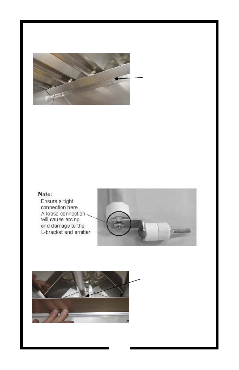
The Teflon sheeting on the tray is a durable nonstick material.
However, it is not indestructible. It is wise to exercise care when
using it. For example, avoid sliding hard objects across the sur-
face. As with other materials, the surface will degrade over time.
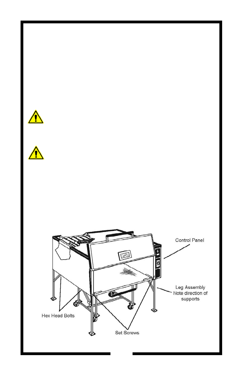
Oven Setup
4
4. If you have a 5A model, install the casters on the cart using
the hardware provided.
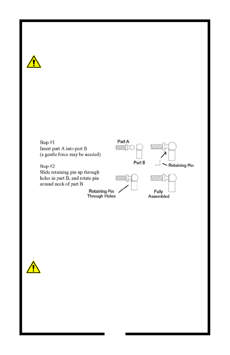
5. Lift the lower section of the cart high enough to accept the
gas spring, then rotate the gas spring upward until the male
portion fits into the female portion of the cart. Insert the bolt
and lightly tighten the lock nut against the mount. Do not
over tighten as this is a pivot point.
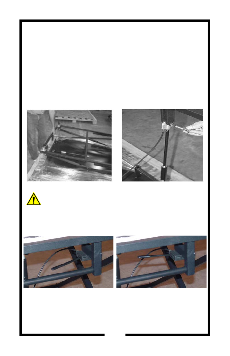
6. Flip the cart over onto the wheels. Then carefully remove and
unpack the Teflon sheeted tray and replace it on the cart. Ad-
just the cart height using the quick release lever. (Use the
upper level for flat plastics and the lower level for bubble
forming)
UNLOCKED
Cart may be raised or lowered
to required height
LOCKED
Cart height is now locked into
osition