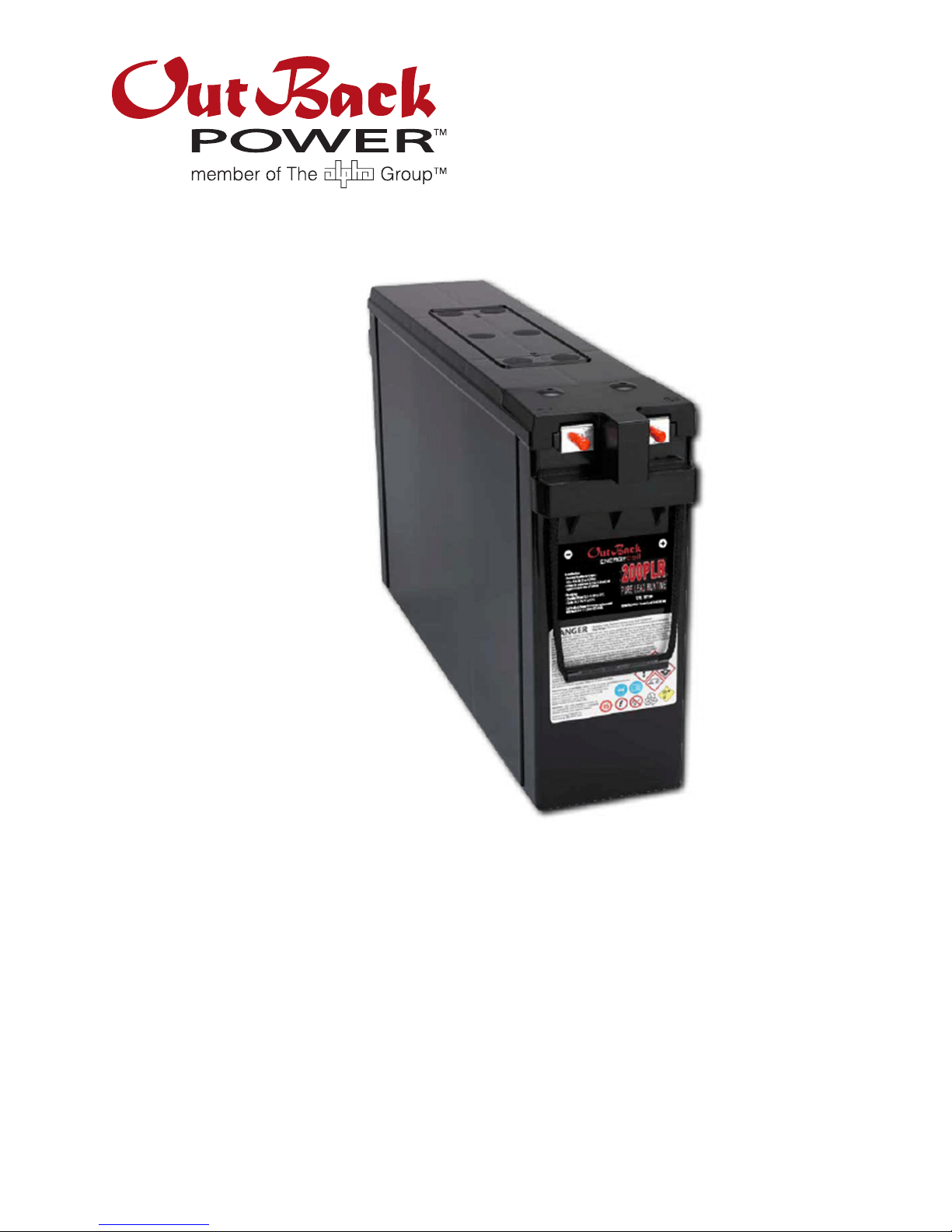
Installation and Operation
900-0230-01-00 Rev A
7
Self-Discharge
All EnergyCell batteries will discharge over time once charged, even in storage. Higher storage
temperatures increase the rate of self-discharge. The EnergyCell PLR has a longer shelf life
than other VRLA batteries. At room temperature (77°F or 25°C), the EnergyCell PLR has a
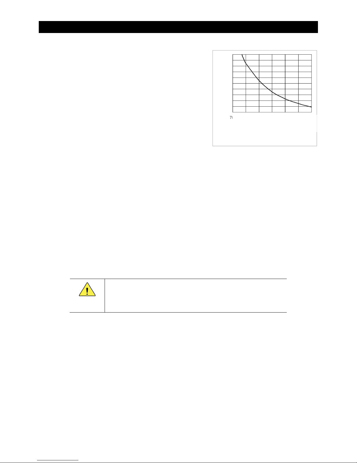
shelf life of 18 months before self-discharging to unacceptable levels. Figure 2 shows the rate
of EnergyCell PLR self-discharge at various temperatures.
Fully charged, the natural (“rest”)
voltage of all EnergyCell batteries is
approximately 12.8 Vdc. A battery
should have a freshening charge (see
page 14) if its rest voltage is below
12.5 Vdc per battery (2.08 Vdc per cell).
A battery should not be used if its rest
voltage is 12.0 Vdc or lower upon
delivery. Contact the vendor upon
receiving a battery in this state.
No EnergyCell should ever be
permitted to self-discharge below
70% state of charge (SoC). Such a
condition is highly detrimental and
will shorten battery life. (This situation is
not the same as discharging to 70% SoC
or lower under load. See page 8.)
Storing EnergyCell PLR Batteries
The EnergyCell PLR must be kept in storage no longer than the shelf life in Figure 2 for a
particular temperature. At the end of this time it must be given a freshening charge. That is, a
battery stored at 104°F (40°C) should be stored no longer than six months, while it can be
stored up to 48 months at 50°F (10°C) without a charge.
Stored batteries should be checked for open-circuit voltage at intervals. Any time the battery
voltage is less than 2.10 Vpc (volts per cell; this equates to 12.6 volts per battery), it should be
given a freshening charge regardless of the storage time.
At 104°F (40°C), the EnergyCell PLR voltage should be checked every 2 months. At 86°F
(30°C), the interval is 3 months. At 77° to 68°F (25° to 20°C) the interval is 4 months. At
temperatures lower than 59°F (15°C), the voltage only needs to be checked every 6 months.
Capacity
Battery capacity is given in ampere-hours (amp-hours). This is a current draw which is
multiplied by the duration of current flow. A draw of X amperes for Y hours equals an
accumulation of XY amp-hours.
Because the battery’s chemical reaction constantly releases energy, its level of depletion is not
always obvious. Smaller loads will deplete the batteries less than larger loads. This effectively
means that the battery has more capacity under lighter loads.
For example, if the EnergyCell 200PLR is discharged at the 20-hour rate to a voltage of 1.75
Vpc (a load expected to effectively drain 100% of its capacity in 20 hours), it will be measured to
have 203.8 amp-hours. However, at the 4-hour rate, a heavier load, only 177 amp-hours will be
measured. For discharge rates and amp-hours, see Table 4 on page 21.
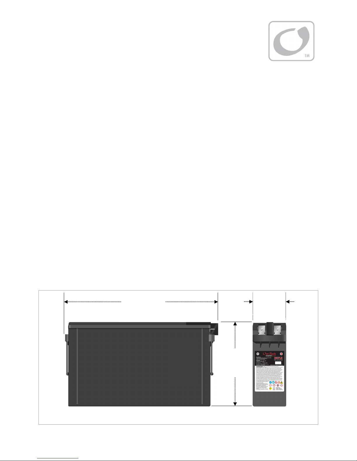
Figure 2 EnergyCell PLR Shelf Life
0 6 12 18 24 30 36 42 48
Months
2.17
2.16
2.15
2.14
2.13
2.12
2.11
2.10
Rest Volts per cell (Vpc)
Approximate %
State of Charge
100
96
91
87
83
79
74
70
40°C
104°F
30°C
86°F 25°C
77°F 20°C
68°F 10°C
50°F