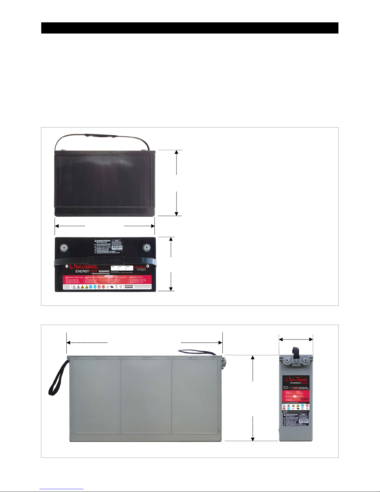
Installation and Operation
8 900-0127-01-00 Rev C
70°F 80°F 90°F 100°F 110°F 120°F 130°F
21°C 27°C 32°C 38°C 43°C 49°C 54°C
Temperature
90
80
70
60
50
40
30
Storing EnergyCell GH Batteries
The EnergyCell GH must be kept in storage no longer than the shelf life indicated in Figure 4 for a particular
temperature. At the end of this time it must be given a freshening charge. That is, a battery stored at 104°F
(40°C) should be stored no longer than six months, while it can be stored up to 48 months at 50°F (10°C) without
a charge.
Stored batteries should be checked for open-circuit voltage at intervals. Any time the battery voltage is less than
2.10 volts per cell (12.6 volts per battery), it should be given a freshening charge regardless of the storage time.
At 104°F (40°C), the EnergyCell GH voltage should be checked every 2 months. At 86°F (30°C), the interval is 3
months. At 77° to 68°F (25° to 20°C) the interval is 4 months. At temperatures lower than 59°F (15°C), the
voltage only needs to be checked every 6 months.
Storing EnergyCell RE Batteries
The EnergyCell RE must be given a freshening charge every six months when stored at 77°F (25°C). The charge
should be every three months if stored at temperatures of up to 92°F (33°C). If stored in higher temperatures,
the charge should be every month.
Capacity
Battery capacity is given in ampere-hours (amp-hours). This is a current draw which is multiplied by the duration
of current flow. A draw of Xamperes for Yhours equals an accumulation of XY amp-hours.
Because the battery’s chemical reaction constantly releases energy, it tends to replenish its own charge to a
minor degree. Smaller loads will deplete the batteries less than larger loads because of this constant
replenishment. This means that effectively the battery has more capacity under lighter loads.
For example, if the EnergyCell 170RE is discharged at the 48-hour rate to a voltage of 1.75 volts per cell (a load
expected to effectively drain 100% of its capacity in 48 hours), it will be measured to have 163.9 amp-hours.
However, at the 4-hour rate, a heavier load, only 120.6 amp-hours will be measured. For discharge rates and
amp-hours of all EnergyCell batteries, see the tables on page 20.
The EnergyCell models are named after their capacity at the 100-hour rate when discharged to 1.75 volts per cell.
State of Charge
The EnergyCell SoC can be determined by two methods. One is to
measure its voltage. This is accurate only if the batteries are left
at rest (no charging or loads) for 24 hours at room temperature
(77°F or 25°C). If these conditions are not met, then voltage checks
may not yield usable results. If they are met, then on average, a
battery at 12.8 Vdc will be at 100% SoC. A rest voltage of 12.2 Vdc
represents roughly 50% SoC.
The more accurate method is to use a battery monitor such as the
OutBack FLEXnet DC. Using a sensor known as a shunt, the monitor
observes the current through the battery. It keeps a total of amp-hours
lost or gained by the battery and can give accurate SoC readings.
The EnergyCell can be discharged and recharged (cycled) regularly
to a level as low as 50% depth of discharge (DoD). This is common in a cycling application such as an off-grid
system. However, for optimal battery life, the best practice is to avoid regular discharge below 50%. The battery
can be occasionally discharged as low as 80% DoD (20% SoC), as is common in emergency backup systems.
However, the best practice is to avoid ever discharging below 80% DoD.
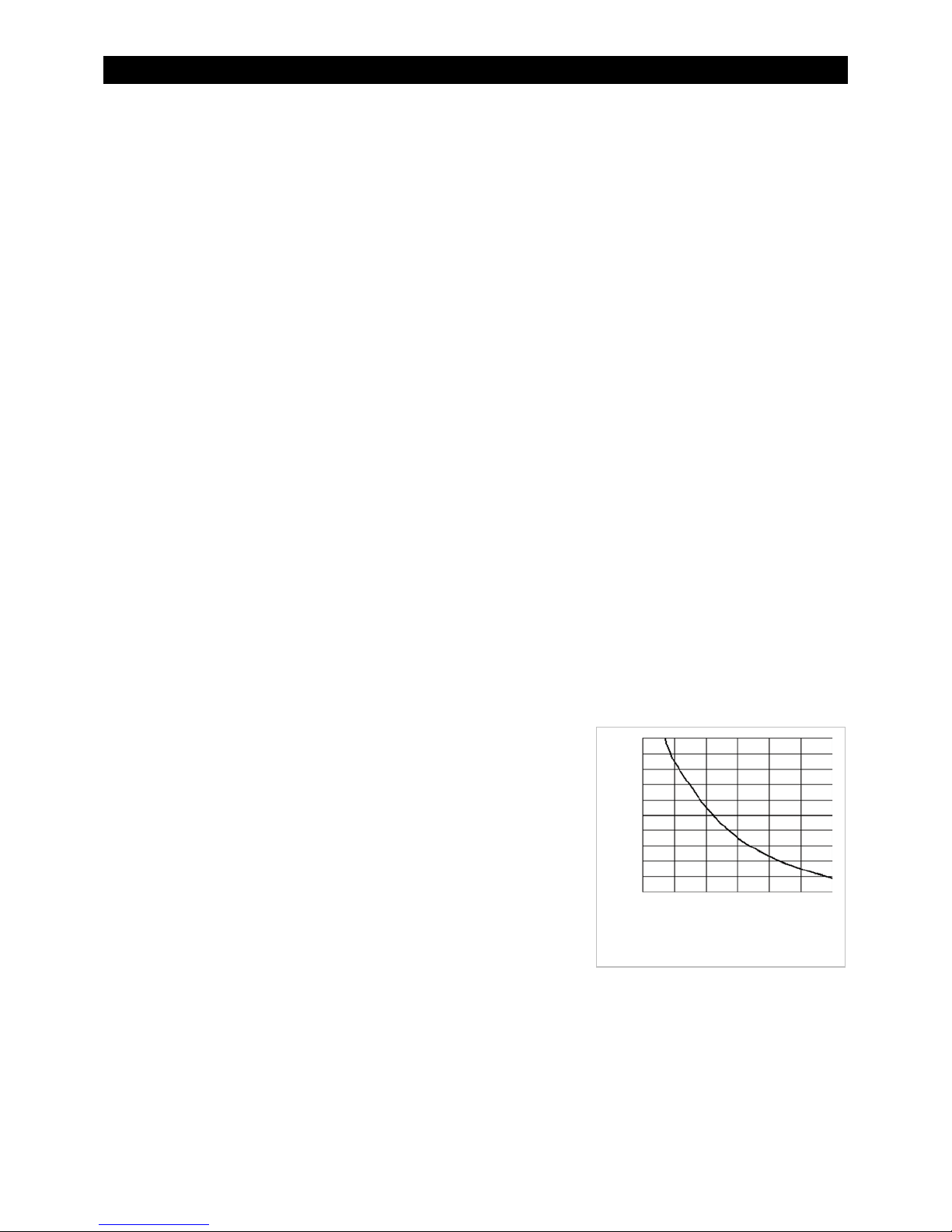
If operated in the recommended range, the EnergyCell will typically have a life of hundreds of cycles. With
consistently lighter discharge, the battery may have thousands of cycles. For the anticipated cycle life of a
particular model, see the OutBack data sheet for that battery. (The cycle life can be affected by temperature.
Figure 5shows the effect of ambient temperature on typical battery life.)