Outdoor Plus WILLIAMS TFL-WILL72RTF User manual

PHONE: (909) 460-5579
EMAIL: [email protected]
ADDRESS: 701 S Dupont Ave. Ontario, CA 91761 U.S.A.
WEBSITE: www.theoutdoorplus.com
OWNER’S MANUAL
THE WILLIAMS FIREPLACE
OWNER’S MANUAL
Thank you for purchasing
the Williams Fireplace.
Save these instructions for future use. If
you are assembling this unit for someone
else, give this manual to him or her to
read and save for the future.
If you have any questions,
please contact customer service
TFL-WILL72RTF
TFL-WILL84RTF
TFL-WILL96RTF
THE WILLIAMS
READY TO FINISH
THE WILLIAMS
READY TO FINISH
WITH SCUPPER
THE WILLIAMS
STAINLESS STEEL
THE WILLIAMS
CORTEN STEEL
THE WILLIAMS
POWDER COAT
TFL-WILL72RTFSC
TFL-WILL84RTFSC
TFL-WILL96RTFSC
TFL-WILL72SS
TFL-WILL84SS
TFL-WILL96SS
TFL-WILL72CS
TFL-WILL84CS
TFL-WILL96CS
TFL-WILL72PC
TFL-WILL84PC
TFL-WILL96PC

DANGER
WARNING
WARNING: If the information in this manual is not followed exactly,
a re or explosion may result causing property damage, personal
injury, or loss of life.
WARNING: For Outdoor Use Only.
FIRE OR EXPLOSION HAZARD
Failure to follow these instructions could result in re or explosion,
which could cause property damage, personal injury, or death.
If you smell gas:
- Shut off gas to the appliance.
- Extinguish any open ame.
- If odor continues, leave the area immediately.
- After leaving the area, call your gas supplier or re depatment.
Do Not store or use gasoline, or other ammable vapors and liquids, in
the vicinity of this or any other appliance.
Installation and service must be performed by a qualied installer,
service agency, or the gas supplier.
INSTALLER: LEAVE THIS MANUAL WITH THE APPLIANCE.
OWNER: RETAIN THE MANUAL FOR FUTURE REFERENCE.
Do Not store or use gasoline, or other ammable vapors and liquids, in
the vicinity of this or any other appliance.
THE WILLIAMS FIREPLACE
INSTALLATION & OPERATION
DANGER CARBON MONOXIDE HAZARD
This appliance can produce carbon monoxide
which has no odor.
Usingit in an enclosed space can kill you.
Never use this appliance in an enclosed space
such as a camper, tent, car or home

SAFETY INFORMATION
The installation of this unit must adhere to local codes or either the National Fuel Gas Code, ANSI
Z223. 1/NFPA54, OR CAN/CGA-B149.1, National Gas and Propane Installation Code.
• THIS UNIT IS INTENDED FOR OUTDOOR USE ONLY! This product shall be used outdoors, in a
ventilated space and shall not be used in any enclosed area.
• This unit is to be used with propane gas only! (sold separately)
• Do not attach a remote gas supply to this unit.
• Only use propane gas for this unit.
• Do not use any solid fuel or charcoal for this unit.
• When igniting this unit, stay away from the burner as the ame will light up and may cause injury.
• LP GAS WARNING: Do not use any more than 1/4in depth lava rocks/pumice stones/LavaGlass
above the burner holes. Doing so will suffocate the ame.
• If the propane gas tank is leaking gas, you may hear, see, or smell a hiss. Do the following:
1. Disconnect the propane gas tank. 2. Do not attempt to x the problem yourself. 3. Contact your gas
supplier or re department for help.
• Applying too much propane may result in gas pooling and will not burn. Allow fresh air into the unit
so that the remaining gas may escape.
• Do not use a ame to check for gas leaks.
• The max. inlet supply pressure: max. Gas supply 11 in w.c. (2.74kPa)
• Use LP propane tanks with the following dimensions: diameter 12 in, height 18 in - capacity 20 lbs.
• You must use a propane tank that has a collar to protect the gas valve.
• DO NOT ll tank over 80 percent full.
• The tank system must be set up for vapor withdrawal.
• Discontinue use if any part of the propane tank is damaged. Rust and dents may be hazardous and
should be inspected by a gas supplier.
• Do not burn anything other than the provided materials for this re table.
• Keep away from the unit for the rst 20 minutes after igniting your unit for the rst time, as lava
rocks/pumice stones/LavaGlass could pop out and cause injury. Should any rocks pop out, discard
them.
• Always ensure that lava rocks/pumice stones/LavaGlass are completely dry before use. Failure to
do so will cause them to crack or pop.
• Do not operate unit until all parts are fully assembled.
• Do not paint or color any part of this heating unit.
• Unit may be hot while in use, do not attempt to move it while in use.
• Never leave this heating unit unattended while in use.
• This unit is not intended for cooking.
• Keep any ammable items away and do not use any other replace cover for this unit.
• Keep a safe distance to avoid burning skin or clothing.
• Do not sit or rest hands or feet on this heating unit.
• Never place hands or ngers on upper portion of this unit while in use.
• Keep all electrical cords and fuel supply hose away from heated surfaces.

SAFETY INFORMATION
• Combustible material should not be within 72 inches of the top of the unit, or within 48 inches
around the entire unit.
• Keep the appliance area clear and free from combustible material, gasoline and other ammable
vapors and liquids.
• If the ame goes out while burning, turn the gas valve off. Wait 5 minutes before repeating the initial
lighting procedure. Once you have a ame started, hold down the control knob for 1 minute.
• Do not add water into the unit.
• Do not operate unit if any part has been under water. Immediately call a qualied service
technician to inspect the appliance and replace any part of the control system and any gas
control that has been under water.
• Do not disconnect any part while unit is in use.
• Do not store a spare propane tank on or near this unit.
• If the heating unit is indoors, detach the propane tank and leave outdoors.
• Do not operate on a boat or vehicle. This unit must be used on a at surface and outdoors ONLY.
• Always remove protective cover before operating (if applicable).
• Do not set the protective cover over the unit until it is turned off and completely cooled down.
• Check for leaks after not using the unit for long periods of time.
• Children should never operate this unit. Children must be supervised while near this unit.
• Keep gas tank at least 5 feet away from unit when lit. (if external tank)
• The maximum gas supply pressure is 250psi.
• All installation and repair should be done by a qualied professional. This unit should be
inspected annually and cleaned regularly.
• Inspect all elements of this heating unit before each use. If there is damage, the burner must be
replaced.
• Keep the hose out from any pathways to eliminate any accidental damage. (if external tank)
• Be aware of the hazards of high temperatures and stay away from the unit to avoid any burns or
injury.
• The gas supply tank should be constructed and marked with the specications for the LP gas tanks
of the U.S. Department of Transportation or the National Standard of Canada CAN/CSA-B339, LP gas
tanks, spheres and tubes for Transportation of Dangerous Goods; and Commission.
• The LP gas tank must have a listed overlling prevention device and a QCCI or Type I, (CGA810) LP
gas tank connection.
• This heating appliance should not be used on plastic or articial wood decks.
• Children and adults should be alerted to the hazards of high surface temperatures and should
stay away to avoid burns or clothing ignition.
• Young children should be carefully supervised when they are in the area of the appliance.
• Clothing or other ammable materials should not be hung from the appliance or placed on or
near the appliance.
• Any guard or other protective device removed for servicing the appliance shall be replaced
prior to operating the appliance.
• Installation and repair should be done by a qualied service person. The appliance should be
inspected before use and at least annually by a qualied service person. More frequent cleaning
may be required as necessary. It is imperative that the control compartment, burners and
circulating airways of the appliance are kept clean.
IF APPLICABLE:
• Allow heating item to cool completely before placing on lid.
• DO NOT use heating item while lid is installed. Always remove the lid while heating item is in use.

DANGER FLAMMABLE GAS UNDER PRESSURE.
LEAKING LP-GAS MAY CAUSE A FIRE OR EXPLOSION IF IGNITED
CAUSING SERIOUS BODILY INJURYOR DEATH.
CONTACT LP GAS SUPPLIER FOR REPAIRS, OR DISPOSAL OF THIS CYLINDER
OR UNUSED LP-GAS.
WARNING FOR OUTDOOR USE ONLY.*
DO NOTUSE OR STORE CYLINDER IN A BUILDING,
GARAGE OR ENCLOSED AREA.
DO NOT REMOVE, DEFACE, OR OBLITERATE THIS LABEL
*EXCEPT AS AUTHORIZED BY ANSI/NFPA 58.
DANGER: Do not store a spare LP Cylinder under or near a barbecue grill, or other heat sources.
NEVER ll an LP cylinder beyond 80% full: a re causing death or serious injury may occur.
WARNING:
Know the order of LP-gas. If you hear, see
or smell leaking LP-gas, immediately get
everyone away from the cylinder and call the
Fire Department. Do not attempt repairs.
Caution your LP-gas supplier to:
WHEN CONNECTING FOR USE:
Use only in compliance with applicable codes.
Read and follow manufacturer’s instructions.
Consult manufacturer’s instructions
concerning the cylinder connection provided
with you appliance.
Be sure regulator vent is not pointing up.
Turn off all valves on the apploiance.
Do not check for gas leaks with a match or
open ame. Apply soapy water at areas
marked “X”. Open cylinder valve. If bubble
appears, close valve and have LP-gas
service person make needed repairs. Also,
check appliance valves and connections to
make sure they do not leak before lighting
appliance.
Light appliance(s) following manufacturer’s
instructions.
When appliance is not in use, keep the
cylinder valve closed.
LP-gas is heavier than air and may settle in
low places while dissipating.
Contact with the liquid contents of cylinder
will casue freeze burns to the skin.
Do notallow children to tamper or play with
cylinder.
When not connected for use, keep cylinder
valve turned off. Self contained appliances
shall be limited to a cylinder of 30 lb
capacity or less.
Do not use, store or transport cylinder where
it would be exposed to high temperatures.
Relief valve may open allowing a large amount of
ammable gas to escape.
When transporting, keep cylinder secured in an
upright position with cylinder valve turned off.
Be certain cylinder is purged of trapped
air prior to rst lling.
Be certain not to over ll the cylinder.
Be certain cylinder requalication date is
checked.

INSTALLER: LEAVE THIS MANUAL WITH THE APPLIANCE. OWNER: RETAIN THE MANUAL FOR FUTURE REFERENCE.
WARNING: FOR OUTDOOR USE ONLY
Installation and service must be performed by a qualified installer, service agency, or the gas supplier.
DANGER: FIRE OR EXPLOSION HAZARD
If you smell gas:
DANGER: FLAMMABLE GAS UNDER PRESSURE.
Leaking LP-GAS may cause a fire or explosion if ignited causing serious bodily injury or death. Contact LP
Gas supplier for repairs, or disposal of this cylinder or unused LP-GAS.
»Know the odor of LP-gas, if you hear, see or smell leaking
LP-GAS, immediately get everyone away from the cylinder and
call the Fire Department, Do Not Attempt repairs.
»LP-GAS is heavier than air and may settle in low places while
dissipating.
» Contact with the liquid contents of the cylinder will cause freeze burns
to the skin.
» Do not allow children to tamper or play with the cylinder.
»When not connected for use, keep the cylinder valve turned o.
Self-contained appliances shall be limited to a cylinder of 30lbs.
capacity of less.
»Do not use, store, or transport a cylinder where it would be
exposed to high temperatures. The relief valve may open,
allowing a large amount of flammable gas to escape.
»When transporting, keep the cylinder secured in an upright
position with the cylinder valve turned o.
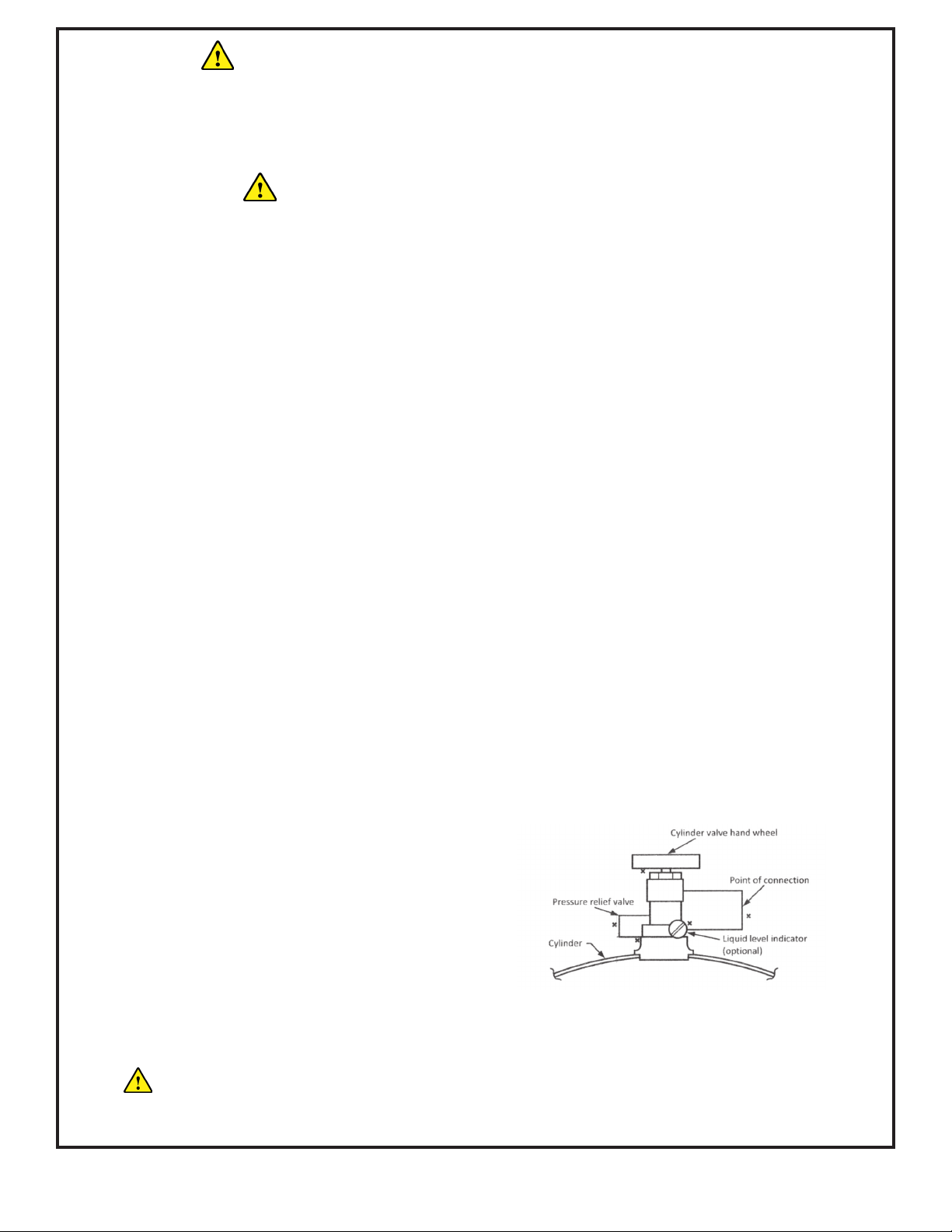
When Connecting for use:
» Use only compliance with applicable codes.
» Read and follow the manufactuer’s instructions.
» Consult the manufacturer’s instructions concerning the
cylinder connection provided with your appliance
» Be sure the regulator vent is not pointing up.
» Turn o all valves on the appliance.
» Do not check for gas leaks with a match or open flame. Apply
soapy water at areas marked “X”. Open the cylinder valve if bub-
bles appear, close the valve, and have the LP-gas service person
make needed repairs. Also, check the appliance valve and con-
nections to ensure they do not leak before lighting the appliance.
» Light appliance following manufacturer’s instructions
» When the appliance is not used, keep the cylinder valve closed.
CALIFORNIA PROPOSITION 65 WARNING
This product can expose you to Carbon Monoxide, which is known
to the state of California to cause cancer and birth defects or other
reproductive harm. (For more information, go to: www.p65warnings.ca.gov)
» Do not store or use gasoline or other flammable vapors and liquids, In the vicinity of this or
any other appliance.
» An LP-Cylinder not connected for use shall not be stored in the vicinity of this or any other
appliance.
» For use with Natural or Propane gas only.
» If the information in this manual is not followed exactly, a fire or explosion may result causing
property damage, personal injury, or loss of life.
» Shut o gas to appliance.
» Extinguish any open flame.
» If odor continues, leave the area immediately.
» Aer leaving the area, call your gas supplier or Fire department.
Failure to follow these instructions could result in fire or explosion, which could cause
property damage, personal injury, or death.
WARNINGS
THIS SECTION OUTLINES WARNING ASSOCIATED WITH INSTALLATION, USE, AND OPERATION.

INSTALLER: LEAVE THIS MANUAL WITH THE APPLIANCE. OWNER: RETAIN THE MANUAL FOR FUTURE REFERENCE.
Instructions are also available at theoutdoorplus.com, Please carefully follow the instructions in
this manual to prevent personal injury or property loss. Instructions are updated as needed. It is the
installer’s responsibility to periodically review instruction for applicable updates.
WARNINGS: Contains information critical to the safe installation and operation of the fireplace.
WARRANTY REQUIREMENT: Must be strictly followed to qualify for product warranty. Warranty will
be void if not followed.
IMPORTANT: Are notes and insights to help ensure product satisfaction and serviceability.
WARNINGS:
» It is the installer’s responsibility to ensure a safe installation and to educate the end user as to
proper operation. Leave this manual with the end user.
» Never alter product or configuration in any way.
» We suggest that our products be installed by professionals that are locally licensed by the
authority having jurisdiction in gas piping. We suggest that our products be serviced annually by a
professional certified in the US by the National Fireplace Institute (NFI) as NFI Gas Specialists or in
Canada by WETT (Wood Energy Technical Training). Installer must follow all instructions carefully
to ensure proper performance and safety.
» The Outdoor Plus Company, Inc. is not responsible for your actions.
» Product is not intended to be a starter for wood or any other combustibles.
» Only use gas/fuel type specified for this fireplace see label on the fireplace control Box.
» Verify correct gas/fuel type and pressure. Never use an alternative fuel to include bio-fuel, ethanol,
lighter fluid or any other fuel.
» Gas pressure and type should be checked prior to use and installation.
» DO NOT USE this appliance if any part has been under water. Immediately call a qualified service
technician to inspect the appliance and to replace any part of the control system and any gas
control which has been under water.
IT IS THE RESPONSIBILITY OF THE INSTALLER TO FOLLOW:
» The National Fuel Gas Code, ANSI Z21.97-(2017)/NFPA 54 or International Fuel Gas Code.
» The National Electrical Code, ANSI/NFPA 70.
» Local Codes
SUPPLY PRESSURE MIN/MAX:
Natural Gas:
Supply Pressure:
Minimum: 3.5” W.C. .87 kPa
Nominal: 7” W.C. 1.74 kPa
Maximum: 14” W.C. 3.48 kPa
Liquid Propane Gas:
Supply Pressure:
Minimum: 8” W.C. 1.99 kPa
Nominal: 11” W.C. 2.73 kPa
Maximum: 14” W.C. 3.48 kPa
IMPORTANT SAFETY INFORMATION
TECHNICAL SUPPORT, SYMBOL, LEGEND, SAFETY INFORMATION FOR INSTALLERS & END-USERS

EXPERT TECHNICAL SUPPORT | MADE IN THE U.S.A. | 701 S. DUPONT AVE. ONTARIO, CA 91761 U.S.A.
SECTION 1 | COMPONENTS OVERVIEW........................................................................................9
SECTION 4 | OPERATION SEQUENCE.........................................................................................11
SECTION 5 | SELECTING THE LOCATION....................................................................................12
SECTION 6 | ENCLOSURE CONSTRUCTION...............................................................................13
SECTION 7 | PRE-PLANNING CHECKLIST..................................................................................14
SECTION 8 | INSTALLATION INSTRUCTIONS............................................................................15
SECTION 10 | CONNECTING YOUR GAS LINE............................................................................22
SECTION 11 | HOW TO TURN ON YOUR MATCH LIT SYSTEM...................................................24
SECTION 12 | HOW TO TURN ON YOUR MATCH LIT WITH FLAME SENSE..............................25
SECTION 13 | HOW TO TURN ON YOUR FLAME SENSE WITH SPARK IGNITION....................26
SECTION 14 | HOW TO TURN ON YOUR LOW VOLTAGE ELECTRONIC IGNITION SYSTEM....28
SECTION 15 | HOW TO TURN ON YOUR PLUG & PLAY READY SYSTEM..................................30
SECTION 16 | TROUBLESHOOTING............................................................................................31
SECTION17| MAINTENANCE.......................................................................................................34
SECTION 18 | REPLACCEMENT PARTS........................................................................................36
SECTION 19 | CLEARANCE FROM COMBUSTIBLES...................................................................37
SECTION 16 | WARRANTY INFORMATION..................................................................................39
TABLE OF CONTENTS
DIRECTORY OF PAGES & SECTIONS

Installation must conform with local codes or, in the absence of local codes, with the National Fuel Gas Code,
ANSI Z223.1 / NFPA 54, or International Fuel Gas Code.
The appliance when installed, must be electrically grounded in accordance with local codes, or in the ab-
sence of local codes, with the National Electrical Code, ANSI/NFPA 70; or the Canadian Electrical Code, CSA
C22.1, if applicable.
When an appliance is for connection to a fixed piping system, the installation must conform with local codes,
or in the absence of local codes with the National Fuel Gas Code, ANSI Z223.1 * NFPA 54; National Fuel Gas
Code; Natural Gas and Propane Installation Code, CSA B149.1; or Propane Storage and Handling Code, CSA
B149.2, as applicable.
COMPONENTS OVERVIEW
ELECTRONICS
GAS VALVE AND PILOT COMPONENTS
» Certified to ANSI Z21.97-(2017) / CSA 2.41-(2017)
» Listed LC Certied
» Durable connections designed to resist outdoor
conditions.
» Electronics are certified for CAN/CSA-E60730-1,
ANSI Z21.20-2014, CAN/CSA-C22.22 No.60730-2-
5-14, UL 60730-2-5 Edition 3, & UL 60730-1.
» 12 or 14 VAC for installations within 5 feet of
water. 110V for installations must be farther than
5 feet from water.
» Potted control module to protect against
moisture and damage.
»The manual key valve is CSA certified to ANSI Z21.15/
CSA9.1
» The pilot is CSA Certified to ANSI Z21.20
» Coils are encapsulated to protect against
moisture.
» Pilot has robust flame pattern, wind resistant.
» Pilot injectors are stainless steel.
» TC Flame-sense system.
» Hot Surface Igniter (HSI).
» LED diagnostics.
» Hot Surface Ignition (HSI), provides stable burner
ignition in harsh conditions.
» Thermocouple Flame Sense, fast responding and
resistant to wind, moisture and corrosion.
» LED diagnostics for field service and
troubleshooting.
» Thermocouple is nickel plated for durability.
» Hot Surface Igniter (HSI) with protective cage.
» Hot Surface Igniter (HSI) connection is
waterproof.
» The Power Wire connector is waterproof.
» LED diagnostics for field service and
troubleshooting.
COMPONENTS OVERVIEW
THIS SECTION OUTLINES THE FEATURES OF THE PLUG & PLAY TO LOW VOLTAGE PANS & BURNERS

GAS CONNECTION
Installation or repair should be performed by a qualified service technician who is locally licensed. The ap-
pliance
should be inspected before use and at least annually by a qualified technician.
DO NOT remove any decal/rating plates from the Electronic Ignition Valve. A gas shut o must be installed
outside the exterior of the fire feature for emergency shut o and maintenance. A sediment trap is highly
recommended to alleviate any problems from debris or sediment in the gas line. It is the installers responsi-
bility
to ensure the fuel supply and line are adequate to supply the maximum BTU for the burner used.
Note: a heat shield/plate MUST be installed between the Electronic Ignition Valve and the burner ring to
avoid
over heating.
The Electronic Ignition Valve box is pre-mounted to the burner or burner & pan combination.
The Electronic Ignition Valve is designed to automatically close the gas valve and shut down should tem-
peratures
exceed 175° Fahrenheit. To keep the unit cool, proper ventilation and a heat shield must be provided.
The Outdoor Plus Recommends a Stainless Steel Whistle-Free Flex Hose to eliminate the noise.
PILOT ASSEMBLY CONNECTIONS
We pre-assemble the pilot on top of the burner pan and in that configuration, the pilot line, thermocouple
and igniter lead should be lowered through a hole in the pan prior to connecting to the control box. The
pilot comes pre-assembled from the factory, so the installer can simply connect the assembly to the
main control box. The igniter has a “shaped” push on waterproof connector ensuring that is can only be
connected the correct way. Push this black plastic connector parts firmly together until it locks in place.
Gently tug on wires to assure connection is secure. The flexible corrugated pilot tube has a flare fitting
that should be connected 1/4 turn past hand tight. Please double check to ensure the fitting is snug both
into the control box and the flare connection. The thermocouple should now be connected. It screws onto
the 11/32” brass fitting on the control box closest to the black connector. It should be snug, but do not
over-tighten.
Next, you may mount the pilot to the burner pan. The shield is designed with perforated material which you
can use to secure to the pan with self tapping screws. The installer can determine the best placement for the
pilot depending on the burner configuration keeping the pilot within 1” from a burner port for quick ignition.
Once all connections are complete, it is highly recommended to perform a leak test. Turn on the gas supply
and using gas test solution or soapy water solution, spray the gas connections on the Electronic Ignition
Valve
including the pilot connector to ensure it is leak free.
COMPONENTS OVERVIEW CONT’D
THIS SECTION OUTLINES THE FEATURES OF THE PLUG & PLAY TO LOW VOLTAGE PANS & BURNERS
10

OPERATIONS
When powdered, indicating a call for heat, the unit will wait for Pre-
Purge time. The HSI will be energized for Trail-For-Ignition time. The HSI
will turn o aer Ignition Time. The HSI will turn o if the flame is de-
tected on the thermocouple before the trail’s end for ignition time. The
main valve will turn on, and the pilot valve will remain on until power is
removed or the flame signal is lost. If the flame is lost, the control will
turn o the gas valve, and aer the flame loss recycles delay, restart
the ignition sequence. If a flame is not detected during the Trail-For-Ig-
nition time and Trails-For-Ignition remains, the pilot and HSI will turn
o and wait for the Inter-Purge time before starting the next ignition
attempt. Suppose a flame is detected before turning on the gas valve. In
that case, the control will stop sequence and remain in safety shutdown
until the flame signal is below the minimum threshold or drops continu-
ously by the minimum threshold valve before continuing.
OPERATION SEQUENCE
THIS SECTION DEMONSTRATES THE OPERATION SEQUENCE OF OUR PLUG & PLAY TO LOW VOLTAGE PANS & BURNERS.
POWER ON
VALVE IS GOOD
YES
YES
YES
YES
YES
YES
YES
YES
YES
YES
NO
NO
NO
NO
NO
NO
RESTART CYCLE
NO
SOURCE
SOURCE
SOURCE
SOURCE
INDICATION
INDICATION
INDICATION
INDICATION
SOURCE
SOURCE
SOLUTION
SOLUTION
SOLUTION
SOLUTION
SOLUTION
SOLUTION
SOLUTION
SOLUTION
SOLUTION
SOLUTION
SOLUTION
SOLUTION
SOLUTION
SOLUTION
NO/SOLUTION
NO/SOLUTION
START UP
(STEADY LIGHT)
CONTINUOUSLY BLINKING
FLAME IS STILL ON
GAS LEAK
CONTINUOUSLY
BLINKING
(THERMOCOUPLE TOO HOT OR MOTH-
ER BOARD IS BAD)
BAD BOARD
BAD BOARD
BAD BOARD
BAD VALVE OR BAD BOARD
BAD GLOW PLUG
SEND FOR REPAIR
SEND FOR REPAIR
SEND FOR REPAIR
SEND FOR REPAIR
SEND FOR REPAIR
REPLACE GLOW PLUG
BAD GAS PRESSURE
(Gas Pressure should be
7”W.C - 13” W.C”)
BAD GAS PRESSURE
(Gas Pressure should be
7”W.C - 13” W.C”)
VALVE OPEN
(3 BLINKS = VALVE OPENING)
GLOW PLUG ON
MAIN VALVE OPEN
BURNER ON
(STAYS ON)
SAFLEY SHUT DOWN
(EVERYTHING SHUTS OFF)
11

SELECTING THE LOCATION
THIS SECTION DEMONSTRATEWS LOCATION REQUIREMENTS & WARNINGS
WARNING:
All fireplaces, match lit kits, spark ignition, safety pilot and Electronic Ignition Components are
designed and intended for outdoor use only.
» All fireplaces must have a gas shuto on the outside of the exterior of the fireplace to allow for emergency
shut o and maintenance. DO NOT PLACE ON TOP OF NON-COMBUSTIBLE FLOORING.
» Select a location where the fireplace can be attended during operation. Never leave an operating
fireplace unattended or by someone not familiar with its operation or emergency shut o locations.
» Both children and adults should be alerted to the hazards of high surface temperatures and
should stay away to avoid burns and clothing ignition.
» Young children should be carefully supervised when they are in the area of fireplace.
» Clothing or other flammable materials should not be placed on or near fireplace.
» Fireplaces create very high temperatures - Combustibles must be located far enough away that
there is no risk of ignition.
WARNING:
Venting is required to dissipate heat and any residual fuel. Failure to provide proper ventilation could result
in overheating and or explosion. See Proper Venting topic in the Enclosure Construction Section.
» Select a location with proper drainage.
» Choose a location that allows easy access for installation and maintenance of the fireplace.
» Pick a location that allows suicient horizontal room to enjoy the fireplace while allowing a safe
distance from the heat and flame.
IMPORTANT:
» It is recommended that material such as granite, marble or other dense stone be kept away from
heat and especially flame due to risk of cracking. Manufacturer is not responsible for damage.
CLEARANCE FROM COMBUSTIBLES | UP TO 65K BTUS | SEE SECTION 15
CLEARANCE FROM COMBUSTIBLES | 66K TO 200K BTUS | SEE SECTION 15
CLEARANCE FROM COMBUSTIBLES | 201K TO 400K BTUS | SEE SECTION 15
Under Valve Box When Applicable 2” For Drainage
Sides Surrounding Fireplace 36” From Structure or Combustibles
Overhead Clearance Min. 84” Overhead Clearance
Under Valve Box When Applicable 2” For Drainage
Sides Surrounding Fireplace 48” From Structure or Combustibles
Overhead Clearance Min. 96” Overhead Clearance
Under Valve Box When Applicable 2” For Drainage
Sides Surrounding Fireplace 48” From Structure or Combustibles
Overhead Clearance NO OVERHEAD CONSTRUCTION
12

ENCLOSURE CONSTRUCTION
THIS SECTION OUTLINES THE CONSTRUCTION OF THE FIRE FEATURE ENCLOSURE REQUIREMENTS & WARNINGS
WARNING:
» All fireplaces must have a gas shuto on the outside of the exterior of the fireplace to allow for
emergency shut o and maintenance.
» Always use proper materials and construction for gas supply, power and enclosure.
» The enclosure must incorporate 1 vent on at least two opposing sides (2 vents total) at a minimum
size of 18 sq. inches of total free area each (Example: 3”x 6” or larger). Installation of the vents
in the mid to lower area of the enclosure is recommended. Ventilation allows for heat and or
residual fuel to escape. Failure to properly vent enclosure may result in the fire-pit overheating or
explosion. Some enclosures may require more ventilation based on material, size, and extended
use. The vent may work as a drain as well when installed at bottom sidewall to prevent water
build up.
» The interior void space of the enclosure surrounding the valve box cannot be filled with any
material (gravel, crushed rock, concrete, etc.)- It is a requirement to have a minimum of 2” under
the valve box for proper ventilation and drainage.
» Select materials that are non-combustible in both initial installations as well as over time.
» The fireplace assembly should be recessed a minimum of 2.25” from the top of the enclosure to
protect flame from being blown out. Some areas may require more- 4 to 6” is not uncommon.
WARRANTY REQUIREMENT:
» The enclosure must be constructed on a stable surface. The weight of the fireplace must be
supported by the pan and not by any control/valve box. For Electronic Ignition Component models
the control/valve box must be above grade with adequate drainage to prevent water damage to
the controls inside the box.
IMPORTANT:
▪ Make sure that the structure is level. We recommend the use of the installation collar (optional)
that may be mortared into the surround.
▪ The Outdoor Plus recommends that the pan lip is recessed on trough (linear). The Outdoor Plus
cannot guarantee the lip on all of our products will be perfectly flat and will not warp due to heat.
▪ Product must be accessible for service.
PROPER VENTING
▪ Certain fireplace enclosures may require extra ventilation depending on size, material or extended
use.
▪ 1 Square Inch of ventilation is REQUIRED for every 25,000 BTUs.
▪ This is especially important for propane units, as propane gas is heavier than air and can pool in
the bottom of an enclosure.
WARNING: Venting is required to dissipate heat and any residual fuel. Failure to provide proper ventilation
could result in overheating and or explosion.
13

PRE-PLANNING CHECKLIST
THIS SECTION DEMONSTRATES THE PROPER INSTALLATION AND TESTING OF THE PLUG & PLAY TO LOW VOLTAGE SYSTEMS.
TO ENSURE PROPER INSTALLATION PLEASE USE THIS PRE-PLANNING CHECKLIST:
Recommended Tools:
General Plumbing Tools (Pipe Wrench, Crescent Wrench, Pipe Cutters, etc.)
Manometer (To test static & dynamic gas pressure)
Voltmeter (To check voltage & amperage to unit)
Gloves
Mini-Butane Torch
Cordless Drill
Dielectric Grease or Silicone (For waterproofing wire nuts)
Whistle-free Stainless Steel Flex Gas Hoses (TOP does not recommend using the standard yellow
corrugated flex gas hoses as those cause a loud persistent whistle sound to occur when using the fire
feature)
Ensure the location is free of combustibles (See section 11 for more information.)
Measure & record distances of gas piping & electrical conduit runs, these will be useful for calculating
gas pressure and proper wiring. The distance and wire gauge DIRECTLY aects the performance of the
Electronic Ignition Component.
The Fire Feature is delivered on a pallet via freight and placed in front of your home. Please have a team
of movers ready to help move the unit from the curbside/driveway to the desired location. ALWAYS
inspect the pallet for damage or missing pieces, if there is damage or missing pieces please DO NOT sign
for the pallet and call our support team immediately to help resolve any problems.
All fire features require a hollow area underneath the pan for serviceability of the unit, DO NOT FILL the
hollow basin with sand or any other media.
Gas Risers should come up to a maximum height of 2” from the ground and use a 90-degree fitting to
help reduce the basin height and allow for easy servicing.
TOP DOES NOT RECOMMEND to use the standard yellow corrugated gas flex hoses with its fire features,
TOP recommends to use a Whistle-Free Stainless Steel Gas Flex Hose in order to help eliminate any
whistling sounds.
Ensure you use the Home-run method for connecting multiple Electronic Ignition Component units, DO
NOT DAISY CHAIN these units.
Ensure you ordered the right gas type and ignition type for your installation.
14

INSTALLATION INSTRUCTIONS
THIS SECTION DEMONSTRATES THE PROPER INSTALLATION AND TESTING OF THE PLUG & PLAY TO LOW VOLTAGE SYSTEMS.
STEP 1 | SELECTING A LOCATION
» Please see Section 5 on Selecting a location for instructions.
STEP 2 | VENTILATION & ENCLOSURE CONSTRUCTION
» Please see Sections 6 & 10 on ventilation & enclosure construction instructions.
» Ensure lava is not overfilled and do NOT cover the pilot for electronic electronic ignition valves.
STEP 3 | GAS CONNECTION
» Please see Section 3 for warnings.
» Place a ball valve close to the gas piping coming from the building for safety purposes.
» Gas Flow Pressure Requirements | See Figure 1
» Please reference figure 1 on the next page – We are looking for 7” (Natural Gas) or 11” (Propane) Dynamic
for optimum flow.
» Check dynamic & static gas flow pressure before the Electronic Valve Box.
» If the unit has a manifold please allow at least 10 inches of space in your design for a minimum height ba-
sin for the manifold.
» For appliances for use with a fixed fuel piping system and equipped with an appliance gas pressure
regulator, the appliance and its individual shuto valve must be disconnected from the gas supply piping
system during any pressure testing of the system at test pressures in excess of 1⁄2 psi (3.5kPa)
» The appliance must be isolated from the gas supply piping system by closing its individual manual shuto
valve(s) during any pressure testing of the gas supply piping system at the pressures equal to or less that 1⁄2
psi (3.5 kPa)
STEP 4 | IGNITION OPTIONS
» There are numerous options available to turn on/o your fire feature, you may splice o the three-prong
plug and hard wire the provided unit to a UL certified light switch, pool controller, smart home hub, wireless
remote light switch, etc. Or simply use the provided three-prong plug to a UL Certified outlet, smart outlet
hub, GFCI, or extension cord.
» Please See Figure 3.1, 3.2, 3.3, & 3.4 for a visual reference on the ignition options.
STEP 5 | ELECTRICAL CONNECTION & TESTING
» Only a locally licensed electrician should install the electrical components. Please refer to your
local codes to ensure proper installation.
» Confirm that appropriate voltage and amps (minimum amperage required 2.0-2.2 amps)
» Use Waterproof Wire Nuts to ensure longevity & waterproofing of the wiring
» Use only UL/CSA/LC Certified components with the Plug & Play to Low Voltage Electronic
Ignition Electronic ignition valve.
STEP 6 | APPLYING FIRE MEDIA
» Please see Section 9 on Fire Media Usage
WARNING: TOP does NOT recommend you use fire glass/media on propane fire features, Liquid
Propane is heavier than Natural Gas and can pool up in the burn area and potentially cause a backfire.
15

INSTALLATION INSTRUCTIONS CONT’D
THIS SECTION DEMONSTRATES THE PROPER INSTALLATION AND TESTING OF THE PLUG & PLAY TO LOW VOLTAGE SYSTEMS.
STEP 7 | OPERATION INSTRUCTIONS
▪ Please see Section 11 on Operation Instructions, this section outlines how to operate your Plug & Play to
Low Voltage Pans & Burners fire feature.
HELPFUL TIPS FOR PROPER OPERATION
1. Cross ventilation is REQUIRED! A minimum of 1 square inch of ventilation is required for
every 25,000 BTUs on each side of the installation. Air flow is your friend!
2. Media (lava rock) minimum of 1/2” and no larger than 2” in diameter.
3. Media must not cover the pilot. The pilot needs air. Avoid packing media against the pilot.
4. Media must be approved by the appliance manufacturer.
5. A heat shield/Pan MUST be installed between the burner and Electronic Ignition Valve
6. The Electronic Ignition Valve has a temperature safety shuto at 175° F.
7. Be sure the gas shut o valve is open.
8. If using wire nuts, be sure they are weather proof and use dielectric grease on the wires.
9. The unit is water resistant. NOT water proof! DO NOT PUT IN WATER OR SUBMERGE.
FIGURE 1
GAS PRESSURE REQUIREMENTS
LED DIAGNOSTIC CODES
Pressure Natural Gas Propane Gas
Minimum 3.5” W.C .87 kPa 8” W.C. 1.99 kPa
Nominal 7” W.C. 1.74 kPa 11” W.C 2.73 kPa
Maximum 14” W.C. 3.48 kPa 14” W.C. 3.48 kPa
OFF NO POWER / INTERNAL FAULT
ON NORMAL OPERATION
1 FLASH HOT START, THERMOCOUPLE HOT AT POWER UP
2 FLASHES TRIAL LOCKOUT, MAXIMUM IGNITION TRIALS EXCEEDED WITHOUT FLAME DETECTION
3 FLASHES FLAME LOSS LOCKOUT, EXCEEDED MAXIMUM LOSSES OF FLAME AFTER PROVIDING BURNER ON.
4 FLASHES FLAME SENSE FAULT
5 FLASHES VALVE FAULT
FAST FLASH SAFETY SHUTDOWN
16

INSTALLATION INSTRUCTIONS [LOW VOLTAGE] CONT’D
THIS SECTION DEMONSTRATES THE PROPER INSTALLATION AND TESTING OF THE PLUG & PLAY TO LOW VOLTAGE SYSTEMS.
Figure 2.1 | Using a Pool Controller with 110V Accessories & 12V-14V Control Panel
Figure 2.2 | Using an Automated Pool Controller with a Low Voltage Control Panel
POOL CONTROLLER/
SMART HOME SYSTEM
AUTOMATED POOL CONTROLLER
Aqualink, Pentair, Intellitouch
To Neutral
To Ground
Low Voltage Control Panel
(Capable of powering up to 4 Units)
12V-14V
CONTROL PANEL
GAS
IN
BALL
VALVE
12V OUT110V IN110V OUT
110V IN
BLACK
BLACK
RED
RED
12V-14V
ELECTRONIC
IGNITION
OPTIONAL
110V ACCESSORIES
Remote Control
1-Hr Timer
Emergency Stop
ON/OFF TIMER
REMOTE
GAS
LINE
Pilot Burner Assembly Burner
Burner Pan
Ball Valve
Ignition Control Box
Coupling
Orice
Pilot Burner Assembly
Burner
Burner Pan
17

INSTALLATION INSTRUCTIONS [PLUG & PLAY] CONT’D
THIS SECTION DEMONSTRATES THE PROPER INSTALLATION AND TESTING OF THE PLUG & PLAY TO LOW VOLTAGE SYSTEMS.
Figure 3.1 | Using an Emergency Stop & Dial Timer
FIGURE 3.2 | Using a Standard Light Switch
EMERGENCY STOP
BUTTON ON 110VAC
ALWAYS PLACE FIRST
STANDARD LIGHT
SWITCH 110VAC
(OUTSIDE OF THE FIREPIT)
110V OUTLET
(WITH OUTDOOR COVER)
110V OUTLET
(WITH OUTDOOR COVER)
DIAL TIMER
110VAC
3-PROUND PLUG
3-PROUND PLUG
GAS
LINE
GAS
LINE
Pilot Burner Assembly
Burner
Burner
Burner Pan
Burner Pan
110V
110V
BALL VALVE
BALL VALVE
Ignition Control Box
Orice
Orice
Coupling
Coupling
110V
18

INSTALLATION INSTRUCTIONS [PLUG & PLAY] CONT’D
THIS SECTION DEMONSTRATES THE PROPER INSTALLATION AND TESTING OF THE PLUG & PLAY TO LOW VOLTAGE SYSTEMS.
Figure 3.3 | Using an Emergency Stop & Dial Timer
Figure 3.4 | Using a standard light switch
EMERGENCY STOP
BUTTON ON 110VAC
ALWAYS PLACE FIRST
DIAL TIMER
110VAC
110V - OUT
110V - IN
110V
110V - IN
110V - OUT
GAS
LINE
BALL VALVE
Burner
Burner Pan
Ignition Control Box
Coupling
Orice
Pilot Burner Assembly
GAS
LINE
BALL VALVE
Burner
Burner Pan
Ignition Control Box
Coupling
Orice
Pilot Burner Assembly
STANDARD LIGHT
SWITCH - 110VAC
OUTSIDE OF THE FIREPIT
110V - OUT
110V LEADS
19

INSTALLATION INSTRUCTIONS - THE WILLAIMS WITH SCUPPER
THIS SECTION DEMONSTRATES THE PROPER INSTALLATION AND TESTING OF THE WILLIAMS WITH SCUPPER
20
FIGURE 3.2 | Using a Standard Light Switch
POOL CONTROLLER/
SMART HOME SYSTEM
12V-14V
CONTROL PANEL
GAS
IN
BALL
VALVE
12V OUT
12V-14V
ELECTRONIC
IGNITION
WATER
PUMP
WATER
HOSE
WATER
IN
WATER
IN
WATER
PUMP
WATER
HOSE
OPTIONAL
110V ACCESSORIES
Remote Control
1-Hr Timer
Emergency Stop
Pilot Burner Assembly
Burner Burner Pan
AUTOMATED POOL CONTROLLER
Aqualink, Pentair, Intellitouch
Low Voltage Control Panel
(Capable of powering up to 4 Units)
BLACK
BLACK
RED
RED
GAS
LINE
Pilot Burner Assembly
Scupper
Burner Pan
Ignition Control Box
Coupling
Orice
Scupper
This manual suits for next models
14
Table of contents
Popular Indoor Fireplace manuals by other brands

BuckMaster
BuckMaster 384 user manual

Desa
Desa Comfort Glow GCF26PR OWNER'S OPERATION AND INSTALLATION MANUAL

Heat-N-Glo
Heat-N-Glo 6000CAMP Installer's guide

Dimplex
Dimplex SARATOGA SGA20 instructions

Riello
Riello 40 Series Installation, use and maintenance instructions

Twin-Star International
Twin-Star International 28II300GRA manual

Napoleon
Napoleon GSS42CFN Installation and operating instructions

Thermocet
Thermocet Trimline 100 DB Front installation instructions

IN & OUT HOUSE
IN & OUT HOUSE EF279A instruction manual

Bond
Bond HYFP50095-53 owner's manual

kozy heat
kozy heat CHASKA 29-LOG CSK-29-L Installation and operation manual

barbas
barbas Falcon 73 Installation and maintenance manual