Outlaw 975 User manual


Outlaw Audio Model 975 7.1 Channel Preamp/Processor
2 3
Please Read First
CAUTION: To reduce the risk of electric shock, do not remove the cover.
No user serviceable parts inside. Refer to qualied personnel.
WARNING: To reduce the risk of re or electric shock, do not expose this
appliance to rain or moisture.
The lightning ash with arrowhead, within an equilateral
triangle, is intended to alert the user to the presence of
uninsulated “dangerous voltage” within the product’s enclosure
that may be of sucient magnitude to constitute a risk of
electrical shock to persons.
The exclamation point within an equilateral triangle is intended
to alert the user to the presence of important operating
maintenance (servicing) instructions in the literature
accompanying the appliance.
WARNING: Important Safeguards
Servicing Do not attempt to service the unit yourself as opening or
removing covers may expose you to dangerous voltage or other hazards.
Refer all servicing to Outlaw Audio.
Damage Requiring Service Unplug the unit from the wall outlet
and refer servicing to qualied service personnel under the following
conditions:
»When the power-supply cord or plug is damaged,
»If liquid has been spilled, or objects have fallen into the unit,
»If the unit has been exposed to rain or water,
»If the unit does not operate normally by following the operating in-
structions. Adjust only those controls that are covered by the operating
instructions as an improper adjustment of other controls may result in
damage and will often require extensive work by a qualied technician
to restore the unit to its normal operation,
»If the Model 975 has been dropped or damaged in any way, the unit
should be examined by qualied service personnel.
»When the unit exhibits a distinct change in performance–this indicates
a need for service.
Wall or Ceiling Mounting The unit should be mounted to a wall or
ceiling only as recommended by the manufacturer.
Heat The unit should be situated away from heat sources such as
radiators, heat registers, stoves, or other units (including ampliers) that
produce heat.
IMPORTANT SAFETY NOTE Before connecting a new component
such as the Model 975 to your audio or home theater system it is always
good practice to make certain that all components are turned o, and preferably
unplugged from their AC power source. Many modern electronics products feature
automatic turn-on circuits that may be activated during an installation, causing
the potential for damage to electronic components and/or speakers. Such damage
is not covered by product warranties and Outlaw Audio specically disclaims
responsibility for any such damage.
Precautions
Note to CATV system installer
This reminder is provided to call the CATV system installer’s attention to
Article 820-40 of the NEC, ANSI/NFPA 70, which provides guidelines for proper
grounding and, in particular, species that the cable ground shall be connected
to the grounding system of the building, as close to the point of cable entry as
practical.
FCC Information for User
CAUTION: ANY changes or modications not expressly approved by the
party responsible for compliance could void the user’s authority to operate
the equipment.
This equipment has been tested and found to comply with the limits for a
Class B digital device, pursuant to Part 15 of the FCC Rules. These limits are
designed to provide reasonable protection against harmful interference in a
residential installation.
This equipment generates, uses and can radiate radio frequency energy and, if
not installed and used in accordance with the instructions, may cause harmful
interference to radio communications. However, there is no guarantee that
interference will not occur in a particular installation.
If this equipment does cause harmful interference to radio or television recep-
tion, which can be determined by turning the equipment o and on, the user
is encouraged to try to correct the interference by one or more of the following
measures:
»Reorient or relocate the receiving antenna.
»Increase the separation between the equipment and receiver.
»Connect the equipment into an outlet on a circuit dierent from that to
which the receiver is connected.
Verify The Line Voltage
Your new Model 975 has been factory congured for 120 (+/- 3%) volt AC
lines. Connecting the unit to a line voltage other than that for which it is
intended can create a safety and re hazard, and may damage the Model 975. If
you have any questions about the voltage requirements for your specic model,
or about the line voltage in your area, contact Outlaw Audio before plugging
the unit into a wall outlet.
It is always a good idea to avoid using any audio or video equipment on
the same AC circuit as equipment with motors, such as air conditioners or
refrigerators. This will lessen the possibility of power variation and electrical
start-up noise aecting your sound system.
Power Cord
The removable power cord that is shipped with the Model 975 is specically
designed to be used with this product. DO NOT use any other power cord, as
that may reduce the unit’s performance and possibly create a safety hazard. In
particular, DO NOT use standard IEC type power cords designed for computers
and other business equipment products, as they have a three prong plug that
is not meant for use with the 975. Should the power cord require replacement,
use an identical type, or contact Outlaw Audio for service.
Handle the AC Power Cord Gently
When disconnecting the power cord from an AC outlet, always pull the plug,
never pull the cord. If you do not intend to use the Model 975 for any consider-
able length of time, disconnect the plug from the AC outlet. If the power cord is
replaced, make certain that it is of similar gauge. As with all electrical devices,
do not run power cords under rugs or carpets or place heavy objects on them.
Damaged power cords should be replaced immediately with cords meeting
factory specications.
Wiring
Cables that are run inside of walls should have the appropriate markings to in-
dicate compliance with, and listing by the UL , CSA or other standards required
by the UL, CSA, NEC or your local building code. Questions about cables inside
of walls should be referred to a qualied custom installer, or a licensed electri-
cian or low-voltage contractor.
Installation Location
To assure proper operation and to avoid the potential for safety hazards, place
the unit on a rm and level surface capable of supporting it’s weight. When
placing the unit on a shelf, be certain that the shelf and any mounting hardware
can support the weight of the unit and any additional items in the equipment
rack, or on the shelf.
When positioning the Model 975 in its nal location, make certain that it
has adequate ventilation on all sides, as well as on the top and bottom. In
particular, it is a good idea to provide at least two or three inches of room
above the unit for air circulation. DO NOT place CDs, DVDs, videotapes, owner’s
manuals, or other paper on top of, or beneath, the unit, or in-between multiple
ampliers in a stack. This will block airow, causing heat build-up, degraded
performance, and may create a possible re hazard.
If the unit is to be enclosed in a cabinet or rack, make certain there is adequate
air circulation. Sucient ventilation should be provided so that hot air may exit,
and cool air may enter the cabinet. In some instances, a small cooling fan may
be required to insure adequate airow through the cabinet. If you are in doubt
as to the ventilation requirements for your specic installation, please contact
us. Also, do not place the Model 975 directly on a carpeted surface, as this will
inhibit airow underneath as well as create a potential re hazard.
Avoid installation in humid locations, in extremely hot or cold locations, or in
areas that are exposed to direct sunlight or space heating equipment.
Do Not Open The Cabinet
There are no user serviceable components inside this product. Opening the
cabinet may present a shock hazard, and any modication to the product will
void your guarantee. If water or any metal object, such as a paper clip, coin or a
staple, accidentally falls inside the unit, disconnect it from the AC power source
immediately, and contact Outlaw Audio for further instructions.
Recording Copyright
Recording of copyrighted material for other than personal use is illegal without
permission of the copyright holder.
Safe Antenna and Cable Connection
Outdoor Antenna Installation
Read Instructions All the safety and operating instructions should be
read before the unit is operated.
Retain Instructions The safety and operating instructions should be
retained for future reference.
Heed Warnings All warnings on the unit and in the operating instruc-
tions should be adhered to.
Follow Instructions All operating and use instructions should be
followed.
Cleaning Unplug the unit from the wall outlet before cleaning. The unit
should be cleaned only as recommended by the manufacturer.
Attachments Do not use attachments not recommended by the unit
manufacturer as they may cause hazards.
Water and Moisture Do not use the unit near water–for example, near
a bath tub, wash bowl, kitchen sink, or laundry tub; in a wet basement; or
near a swimming pool.
Accessories Do not place the unit on an unstable cart, stand, tripod,
bracket, or table. The unit may fall, causing serious injury to a child or adult,
and serious damage to the unit. Any mounting of the unit should follow
the manufacturer’s instructions, and should use a mounting accessory
recommended by the manufacturer.
Ventilation Slots and openings in the cabinet are provided for ventila-
tion and to ensure reliable operation of the unit and to protect it from over-
heating, and these openings must not be blocked or covered. The openings
should never be blocked by placing the unit on a bed, sofa, rug, or other
similar surface. The unit should not be placed in a built-in installation such
as a bookcase or rack unless proper ventilation is provided. There should be
free space of at least 16 cm (6 in.) and an opening behind the unit.
Power Sources The unit should be operated only from the type of
power source indicated on the marking label. If you are not sure of the type
of power supplied to your home, consult your unit dealer or local power
company.
Grounding or Polarization The unit may be equipped with a
polarized alternating current line plug (a plug having one blade wider
than the other). This plug will t into the power outlet only one way. This
is a safety feature. If you are unable to insert the plug fully into the outlet,
try reversing the plug. If the plug should still fail to t, contact a licensed
electrician to replace your obsolete outlet. Do not defeat the safety purpose
of the polarized plug.
Power-Cord Protection Power-supply cords should be routed so that
they are not likely to be walked on or pinched by items placed upon or
against them, paying particular attention to cords where they enter a plug,
or a convenience receptacle, and the point where they exit from the unit.
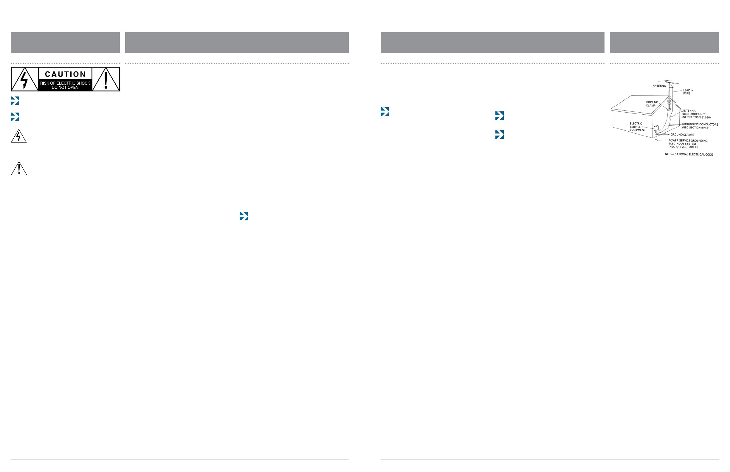
Outdoor Antenna Grounding If an outside antenna or cable system
is connected to the unit, be sure the antenna or cable system is grounded
so as to provide some protection against voltage surges and built-up static
charges. Article 810 of the National Electrical Code, ANSI/NFPA 70, provides
information with regard to proper grounding of the mast and supporting
structure, grounding of the lead-in wire to an antenna-discharge unit, size
of grounding conductors, location of antenna-discharge unit, connection to
grounding electrodes, and requirements for the grounding electrode.
Lightning For added protection for the unit during a lightning storm, or
when it is left unattended and unused for long periods of time, unplug it
from the wall outlet and disconnect the antenna or cable system. This will
prevent damage to the unit due to lightning and power-line surges.
Power Lines An outside antenna system should not be located in the
vicinity of overhead power lines or other electric light or power circuits, or
where it can fall into such power lines or circuits. When installing an out-
side antenna system, extreme care should be taken to keep from touching
such power lines or circuits as contact with them might be fatal.
Overloading Do not overload wall outlets, extension cords, or integral
convenience receptacles as this can result in a risk of re or electric shock.
Object and Liquid Entry Never push objects of any kind into the unit
through openings as they may touch dangerous voltage points or short-out
parts that could result in a re or electric shock. Never spill liquid of any
kind on the unit.
If an outside antenna or cable system is connected to the equipment, be sure
the antenna or cable system is grounded so as to provide some protection
against built up static charges and voltage surges. Section 810 of the national
Electrical Code, ANSI/NFPA 70 (in Canada, part 1 of the Canadian Electrical
Code) provides information with respect to proper grounding of the mast and
supporting structure, grounding of the lead-in wire to an antenna discharge
unit, size of grounding conductors, location of antenna discharge unit, connec-
tion to grounding electrodes and requirements for the grounding electrode.
Keep Antenna Clear of High Voltage Power
Lines or Circuits
An outside antenna system should be located well away from power lines,
electric light or power circuits and where it will never come into contact with
these power sources if it should happen to fall. When installing an outside
antenna, extreme care should be taken to avoid touching power lines, circuits
or other power sources as this could be fatal. Because of the hazards involved,
antenna installation should be left to a professional.

Outlaw Audio Model 975 7.1 Channel Preamp/Processor
4 5
Record your Model 975’s serial number and date of pur-
chase here. The serial number is found on the back panel.
Serial Number
Date of Purchase
The contents of this manual are Copyright © 2014 by Out-
law Audio, LLC., and may not be duplicated or reproduced
by any means, whether physical, electronic or otherwise
without prior written consent from Outlaw Audio, LLC.
Outlaw Audio and the Outlaw Audio logo are registered trademarks of Outlaw Audio,
Inc. “Dolby,” “Pro Logic,” “TrueHD” and the double-D symbol are trademarks of Dolby
Laboratories.
© Dolby Laboratories, Inc. All rights reserved.
“DTS” and “DTS Digital Surround” are trademarks of Digital Theater Systems, Inc.
© Digital Theater Systems, Inc. All rights reserved.
Specications are those in eect at the time of printing. Outlaw Audio, LLC. reserves the
right to change specications or designs at any time without notice, and without obliga-
tion to modify existing units.
Unpacking
Your Model 975 comes in a carton and packing materi-
als designed specically to cushion it from shocks and
vibration commonly encountered in shipping. We strongly
suggest that you save the carton and packing materials,
and use them again if you move or if the unit ever needs to
be shipped back to us for any reason.
To minimize the size of the carton in storage, you may wish
to atten it by carefully opening the top and bottom aps
and folding the carton at. Other cardboard inserts may be
stored in the same manner. Packing materials that cannot
be collapsed should be saved along with the carton in a
plastic bag.
Be careful when lifting and handling the Model 975. The
unit itself is not heavy, but the connectors on the rear
panel and the controls on the front panel can be damaged
by minor impacts.
Save all packing
materials
Chapter 4
Operation
Choose a Device to Operate 37
Power 37
Selecting a Source 38
Volume Control 38
Muting 38
Changing the Surround Mode 39
Switching to Stereo 40
Adjusting the Tone Controls 40
Adjusting the Lip Sync Delay 40
Activating Night Mode (DRC) 41
Adjusting LFE Trim 41
Setting Speaker Size 41
Checking Operating Status 42
Adjusting Channel Levels 42
Listening With Headphones 43
Audio Recording 43
Chapter 5
Tuner Operation
Select Tuner and Band 44
Tune a Station Manually 44
Create Memory Preset Manually 45
Create Memory Preset Automatically 45
Select a Preset Station 45
Entering a Station Manually 46
Select FM Mono 46
Table of Contents
Please Read First
WARNING: Important Safeguards 2
Precautions 3
Outdoor Antenna Installation 3
Unpacking 4
Chapter 1
Model 975 7.1 Channel Preamp/Processor
Model 975 Features 6
Accessories 7
Model 975 Front Panel 8
Model 975 Rear Panel 9
Remote Controls 10
Front Panel Display 15
Audio Formats and Listening Modes 16
Speaker Setup Tips 18
Chapter 2
Connecting Your Model 975
Connecting Audio Components 20
Connecting Video Components 22
Antenna Connections 24
External Amplier Connections 24
Power Control Connections 25
Power Connection 25
Chapter 3
System Setup
Menu Navigation 26
Speaker Setup 28
Input Setup 31
Video Setup 33
Audio Setup 33
Video Output Setup 35
Advanced Dolby/DTS Setup 35
Chapter 6
Remote Control Operation
Programming Using Direct Code Entry 47
Programming Using Auto Code Search 48
Activate Punch-through Volume 48
Deactivate Punch-through Volume 49
Activate Punch-through Channel 50
Deactivate Punch-through Channel 50
Macro Power Mode 51
Restoring Factory Settings 51
Chapter 7
Care and Maintenance
Cleaning 52
When You Are Away 52
System Reset 53
Software Version and Upgrade 53
Troubleshooting Guide 54
Specications 55
Model 975 Connection and Settings Chart 56
Remote Control Codes 57
30-Day Satisfaction Guarantee 60
Outlaw Audio Limited Warranty 60

Outlaw Audio Model 975 7.1 Channel Preamp/Processor
6 7
Model 975
7.1 Channel
Preamp/Processor
Thank you for purchasing the Outlaw
Audio Model 975. This 7.1 channel preamp/
processor is our response to enthusiasts who
requested a simpler pre/pro, one with only the
functions they really need, such as industry-
standard DTS and Dolby surround technologies,
HDMI switching, high-quality digital-to-analog
conversion, and multiple crossover point settings.
This simplicity not only makes the Model 975
compact and aordable, it also makes it easier
to use.
Chapter 1 Contents
6Model 975 Features
7Accessories
8Model 975 Front Panel
9Model 975 Rear Panel
10 Remote Controls
15 Front Panel Display
16 Audio Formats and Listening Modes
18 Speaker Setup Tips
Chapter 1 Overview
In order to get maximum performance from your Model 975,
please take a few minutes to read this manual. It tells you
everything you need to know to connect, congure, and use
this product. By following the steps we list and explain here,
you will get the best possible performance from your speak-
ers, amplier(s), and subwoofer, as well as the best possible
picture and sound from your source components.
If you have any questions about this product, its installa-
tion or operation, please contact us via e-mail at
customerservice@outlawaudio.com or via tele-
phone at 866-OUTLAWS (688-5297).
IMPORTANT: The Model 975 is shipped from the factory
with the following default settings.
Output Conguration 7.1
Loudspeaker Size Small
All Crossovers 80 Hz
Video Output Resolution 720p
Volume -25dB
After reading the rest of this manual, please refer to pages 26-36
to adjust these settings.
Model 975 Features
Your new Outlaw Audio preamp/processor is a high-perfor-
mance audio device, designed to work with practically any
of the wide variety of ampliers and source devices on the
market today. Whether your source is a Blu-ray Disc with
a 7.1-channel DTS-HD Master Audio lossless soundtrack or
an audiophile CD player or even an old cassette deck, the
Model 975’s audio processing technology can handle it
correctly. The Model 975 features:
A. 4 3D HDMI Inputs
Each input is assignable, providing comprehensive
system connectivity.
B. HDMI Output with ARC
Audio Return Channel receives audio signals from a
connected TV.
C. 4 Digital Inputs (2 coaxial, 2 optical)
Each input is assignable, providing comprehensive
system connectivity.
D. 2 Component Video Inputs
High-bandwidth switching circuitry for maximum
picture quality.
E. 2 Composite and 2 S-Video Inputs
High-quality video circuitry for connection to legacy
video sources.
F. 5 Analog Audio Inputs
For easy connection to audio devices that do not oer
digital output, such as iPod docks and phono preamps.
G. High-Denition Video Upscaling
Video coming in through HDMI inputs can be upscaled
from 480p to 720p, 1080i or 1080p, or passed through
at its native resolution.
H. High-performance AM/FM/FM Stereo tuner
Includes memories for 15 FM and 15 AM presets.
I. Dolby TrueHD, Dolby Digital Plus, and Dolby
Digital decoding*; DTS-HD Master Audio, DTS-HD
High-Resolution Audio and DTS decoding**
Decodes all current 5.1 and 7.1 surround-sound formats.
J. Dolby Pro Logic IIz, Dolby Pro Logic IIx, and
Dolby Pro Logic II* and DTS NEO:6** processing
Converts two-channel audio from music and movies
into realistic 5.1 or 7.1 surround sound
K. 192 kHz 24-bit DAC’s for all channels
For high performance audio quality.
L. On Screen Display (via HDMI only)
Provides access to all setup and adjustment menus.
M. Front height-channel outputs
Add new realism to movie soundtracks with Dolby
Pro Logic IIz processing.
N. Separately adjustable subwoofer crossover
points
For the best possible bass reproduction, dierent
crossover points can be set for front left/right, center,
surround, and surround back channels.
O. Programmable universal remote control
Controls the Model 975 as well as a TV and as many as
six other components
P. Low-voltage trigger output
Provides automatic turn on/o of compatible power
ampliers or relay-controlled products such as projec-
tion screens, blinds and lighting systems.
Accessories
After you unpack the Model 975, please check to make sure
the following accessories are in the box:
Owner’s Manual
Universal Remote Control with Batteries
Compact Remote Control with Batteries
AC Power Cord
FM Antenna adapter
FM Antenna
AM Loop Antenna
If any of the above is missing from your shipment, please
contact Outlaw Audio immediately.
* Manufactured under license from Dolby Laboratories.
**Manufactured under license from Digital Theater Systems, Inc.
US Patent No. 5,451,942 and other worldwide patents issued and pending.
HDMI connectivity
Model 975 Front Panel Model 975 accessories
Latest 5.1 and 7.1
digital surround formats
Analog 2-channel to
5.1 and 7.1 surround sound
SRC
PWR
ON
Setup
Mute
OK
Func
+ +
VOL CH
– –
VOL CH
Exit
Menu
Surr Mode AM/FM MEM SpkrSet
Test Direct T.Mode Auto PST
Stereo LFE Trim CH Delay CH Level
Video Game Aux TV
Status Exit Tone Disc
Menu PIP Swap Input
RPT Last CC Sleep
Info FAV Guide VOD
Night Sync
CBL SAT DISC TV
AUX AUD STB TNR
1 2 3
4 5 6
7 8 9
0
OFF
OFF
Status
Surr Mode
Disc Game Aux Video
TV AutoPSTAM/FM Tone
Mute Menu
Tune
Volume
VOL
ENTER
Spkr Set Delay
Test Ch. Select
Night
Stereo
12 3
45 6
7 8 9 0
Direct
Mem
Mono/StereoLFETrim

Outlaw Audio Model 975 7.1 Channel Preamp/Processor
8 9
Before you connect any audio or video components to the
Model 975, it’s important to understand how the dier-
ent buttons, switches, and connections work. Most A/V
source devices now oer several connection options, and
unless you choose the proper ones, you won’t get the best
possible audio and video quality. The following two sec-
tions oer a brief explanation of the front and rear panel
components of the Model 975.
A. STANDBY power button (see page 37)
Pressing this button turns the unit on and o. When
the unit is on, the blue ring around the button glows
brightly and the front panel display illuminates.
When the unit is o, the blue ring glows dimly, the
front panel display turns o, control functions are
disabled, and all outputs are muted.
B. IR sensor
The IR sensor receives commands from the remote
control. Do not block or cover it. If the unit is inside a
cabinet or behind tinted glass doors you may need to
use an optional external IR sensor.
C. Front panel display (see page 15)
Indicates program source, DSP mode, channel inputs,
tuner preset and/or frequency, digital input, volume
level, and other preamp/processor/tuner operating
information. Display is not dimmable.
D. VOLUME control (see page 38)
Adjusts the volume level for the line outputs and the
headphone jack.
E. Headphone jack (see page 43)
This jack can be used with stereo headphones that
have a standard 1/4-inch plug. Headphones with
a miniature 1/8-inch/3.5mm plug (the type found
on smartphones and MP3 players) can also be used
with an adapter, available at most electronics stores.
Inserting a 1/4-inch headphone plug mutes the other
outputs. The VOLUME control adjusts listening level.
F. TUNER button (see page 44)
This button selects the radio tuner. The front panel
display will show which band (AM or FM) is active, and
the frequency of the station currently tuned. Pushing
the button again will toggle between AM and FM.
G. TUNE MODE button (see page 46)
Toggles between stereo and mono FM tuning modes
when the tuner is selected source and the FM band is
selected. Does not operate when AM is selected.
H. INPUT button (see page 37)
Pushing this button repeatedly cycles among the ve
input sources (TV, Disc, Game, Vid, and Aux) and the
AM/FM tuner.
I. SURR MODE button (see page 39)
Press this button repeatedly to activate the matrix
surround sound modes and choose among the various
surround modes provided by the Model 975. The
available surround modes will depend on whether you
are listening to a 2-channel, 5.1 or 7.1 signal, and what
loudspeaker conguration you are using.
J. MUTE button (see page 38)
This button mutes the line and headphone outputs.
Model 975 Front Panel
Model 975
Front Panel controls
Model 975 Rear Panel
connections and switches
Model 975 Rear Panel
A. FM Antenna terminal (see page 24)
Use to connect the supplied FM antenna or an external
75Ω antenna.
B. Component Video Output jacks (see pages 22-23)
Use these jacks to connect to a display with compo-
nent video input, such as a TV or video projector.
C. Component Video Input jacks (see pages 22-23)
Use these jacks to connect devices with component
video outputs such as a DVD player or HDTV tuner.
D. Composite Video Output jack (see pages 22-23)
This jack connects to a display with composite video
input, such as older TVs.
E. Composite Video Input jacks (see pages 22-23)
These two jacks connect to older video devices with
composite video output, such as VCRs, laserdisc play-
ers and vintage video game consoles.
F. HDMI Input jacks (see pages 22-23)
These four jacks provide the best possible audio and
video connection to audio/video source devices with
HDMI jacks. They carry high-denition video and are
the only way to listen to the latest high-resolution for-
mats such as DTS-HD Master Audio and Dolby TrueHD.
G. HDMI/ARC Output jack (see page 23)
Use this output to connect to video displays with HDMI
inputs. If your display has an HDMI input, you will get
the best quality by using this connection. This connec-
tion can also carry audio back from your TV set into the
Model 975, so it can be reproduced through your home
theater sound system.
H. RS-232C connector
This jack allows the Model 975 to be connected to
a computer for software updates. It is also used for
servicing. It cannot be used to control the Model 975.
I. RS-232C control switch
This switch is used to set the mode for the RS-232C
connection. For normal operation, it should be left in
the NORMAL position.
J. DC Trigger output (see page 24)
This jack emits a 12-volt DC trigger signal when the
Model 975’s power is on. Use it to control external
devices (such as a power amplier) with a 3-32 VDC
trigger input. The connected device will turn on and
o automatically, in sync with the Model 975.
K. AM Antenna terminals (see page 24)
Connect the supplied AM loop antenna or an external
AM antenna to these terminals.
L. S-Video Output jack (see pages 22-23)
This jack connects to a display with an S-video input,
such as older TVs.
M. S-Video Input jacks (see pages 22-23)
These two jacks connect to video devices with S-video
outputs, such as S-VHS VCRs and laserdisc players.
N. Analog Audio Input jacks (see pages 20-21)
These ve sets of jacks connect to audio or audio/video
sources with analog outputs. They may be used with
audio-only devices, such as an iPod dock or satellite
radio tuner, and should be used with any audio/video
source device that does not oer digital output.
O. Analog Audio Rec Out jacks (see pages 20-21)
This set of jacks can be used for recording stereo sound
from the currently selected audio or audio/video input.
F RH JIG S
A A B DC FEB H IC GD J
E K L O QM N P

Outlaw Audio Model 975 7.1 Channel Preamp/Processor
10 11
P. 7.1 Output connection (see pages 22-25)
Use these jacks to connect the Model 975 to an
external power amplier. The Sub jack connects to a
powered subwoofer or external subwoofer amplier.
Note that the brown and cream-colored jacks on the
left can be used for back surround or front height
channels (but not both).
Q. Coaxial Digital Input jacks (see pages 22-23)
Use these inputs to connect the coaxial digital audio
signal output from such digital devices as CD, DVD or
LD players. These inputs are fully assignable.
R. Optical Digital Input jacks (see pages 22-23)
Use these inputs to connect the optical digital audio
signal output from such digital devices as CD, DVD or
LD players, or TVs lacking ARC compatibility. These
inputs are fully assignable.
S. AC Input (see page 25)
Use to connect the supplied AC power cord (see Precau-
tions on page 2).
For your convenience, the Model 975 comes with two
remote controls.
The universal remote can control both the functions of
the Model 975 Preamp/Processor and when programmed,
other components in your system. In addition to duplicat-
ing the Model 975 front panel buttons, the universal
remote can control additional functions, including setup
and conguration menus through the on-screen display.
Many buttons on the remote access functions directly
without having to view the on-screen display to make
every adjustment.
The compact remote is designed to duplicate all of the
front panel functions of the Model 975, and also provides
direct access to functions in the Model 975’s on-screen
setup and conguration menus.
The main functions of each button for both remotes are
listed in the next two sections . For complete information
about their use, please refer to the section titled “Remote
Control Operation” on page 47.
Remote Controls
Model 975, hit the TNR button. To operate the functions
of another device in your system, press the appropriate
component selection button (CBL, SAT, DISC, etc.)
The component selection buttons cannot be used to
select the input on the Model 975. To change the
input source on the Model 975, follow the steps in “Selecting
a Source” shown on page 38.
G. 10-key numeric keypad (see pages 45-46)
Use these buttons to select an AM or FM station stored
in memory.
H. MUTE button (see page 38)
This button mutes the sound on all outputs, including
the headphone jack. Press it again to unmute.
I. MENU/EXIT button (see pages 26-35)
Pressing this button toggles the on-screen display
(OSD) menu system on and o. The sound will mute
and the menu will ll the screen. Note that the OSD
functions only on the Model 975’s HDMI output. This
button also acts as the return to the previous menu
or EXIT function on a device that the remote has been
programmed to control.
J. Four-way directional control (see pages 26-35)
Use these four directional buttons (up, down, left, right)
to navigate the on-screen menus. These can also be
used to navigate the menus of devices that the remote
has been programmed to control.
K. VOL +/- control (see pages 38, 48-49)
These buttons raise or lower the volume of the Model
975, as well as devices that the remote has been pro-
grammed to control.
L. OK/FUNC button (see pages 26-35)
Use this button to select items and submenus in the
on-screen display. This button will also operate the
OK/Enter function of a device that the remote has
been programmed to control.
M. CH +/- control (see pages 44, 50-51)
Use these up/down buttons to tune AM/FM stations.
Press and hold the CH + or CH - button for 2 seconds
to scan for the next active frequency. These buttons
can also select the channel on a device that the remote
has been programmed to control.
N. SURR MODE/ button (see page 39)
Press this button to activate the Model 975’s matrix
surround processing. Pressing it repeatedly cycles
through the various matrix surround modes. The avail-
able modes depend on whether you are listening to a
2-channel, 5.1 or 7.1 signal, and on your system’s speaker
conguration. This button also operates the Reverse
Scan function on devices that the remote has been
programmed to control.
O. AM/FM/button (see pages 44 and 46)
This button switches the Model 975’s input to the inter-
nal AM/FM tuner. Pressing it again toggles between AM
and FM. This button also operates the Play function on
devices that the remote is programmed to control.
P. MEM/
button (see page 45)
Use this button to memorize a radio station into a
preset that can be accessed later. Tune the station, press
and hold the MEM button for 1 second, then push the
number on the numeric keypad you wish to use for that
station. It also serves as the Pause button for a device
that the remote has been programmed to control.
Universal Remote
Control Overview
Universal Remote Control
POWER / COMPONENT SELECT / NUMERIC buttons
SRC
PWR
ON
Setup
Mute
OK
Func
+ +
VOL CH
– –
VOL CH
Exit
Menu
Surr Mode AM/FM MEM Spkr Set
Test Direct T. Mode Auto PST
Stereo LFE Trim CH Delay CH Level
Video Game Aux TV
Status Exit Tone Disc
Menu PIP Swap Input
RPT Last CC Sleep
Info FAV Guide VOD
Night Sync
CBL SAT DISC TV
AUX AUD STB TNR
1 2 3
4 5 6
7 8 9
0
OFF
A. LED indicator (see pages 47-51)
This light ashes when the remote is sending command
signals, and during programming of other components.
B. SETUP button (see pages 47-51)
Push and hold this button during the process of pro-
gramming the remote to control other components.
C. SRC PWR button (see pages 47-48, 51)
This button turns the power on and o for any compo-
nent selected using the Device Control Select buttons
D. ON button (see page 37)
Press this button to turn the Model 975 on. This button
does not turn the unit o; use the OFF button for that. It
does not aect other components in your system.
E. OFF button (see page 37)
Press this button to turn the Model 975 o. It will not
turn the power on; use the red ON button for that. It
does not aect other system components.
F. Component selection buttons (see page 37)
Use these buttons to select which device in your A/V sys-
tem the remote will control. To operate the controls of the
Universal Remote Control
SRC
PWR
ON
Setup
Mute
OK
Func
+ +
VOL CH
– –
VOL CH
Exit
Menu
Surr Mode AM/FM MEM Spkr Set
Test Direct T. Mode Auto PST
Stereo LFE Trim CH Delay CH Level
Video Game Aux TV
Status Exit Tone Disc
Menu PIP Swap Input
RPT Last CC Sleep
Info FAV Guide VOD
Night Sync
CBL SAT DISC TV
AUX AUD STB TNR
1 2 3
4 5 6
7 8 9
0
OFF
OFF
Status
Surr Mode
Disc Game Aux Video
TV Auto PSTAM/FM Tone
Mute Menu
Tune
Volume
VOL
ENTER
Spkr Set Delay
Test Ch. Select
Night
Stereo
12 3
45 6
7 8 9 0
Direct
Mem
Mono/StereoLFE Trim
POWER / COMPONENT
SELECT / NUMERIC buttons
These buttons are used to power
the Model 975 on and o, and
to select the components in your
system to control when the remote
is in its programmed mode.
You can also access the setup
menus from here, as well as enter
numbers when needed.
DIRECT ACCESS /
DEVICE CONTROL buttons
These buttons have dual roles. The
labels printed above each button
indicate a direct control function
of the Model 975 operated by
the remote when the TNR button
has been pressed. The labels
printed directly on the buttons
represent functions operated by
the remote control for the device
selected by pressing one of the
system component buttons you’ve
programmed (CBL, SAT, DISC, etc.)
at the top of the remote.
DIRECTIONAL / CHANNEL
and VOLUME buttons
These buttons are used to navigate
through menus, and control volume
and channel selection for the device
being controlled by the remote.
A B DC
F
G
E
HI
Dual Function Universal
Remote Control
Controls both the functions of the
Model 975 Preamp/Processor and
when programmed, other components
in your system.
Compact Remote Control
Duplicates all of the front panel
functions of the Model 975,and also
provides direct access to functions in
the Model 975’s on-screen setup and
conguration menus.
PLEASE NOTE: To operate the
functions of the Model 975,
access the setup menus, or select a
source input, you must rst press
the TNR button. Once pressed,
you can directly control the
functions of the Model 975
indicated by the labels printed
above each button on the remote.

Outlaw Audio Model 975 7.1 Channel Preamp/Processor
12 13
Q. SPKR SET/ button (see page 41)
This button lets you change your speaker congura-
tion settings without going into the on-screen menu.
Push the button repeatedly to select which speaker’s
settings you want to change. Use the directional
control up/down buttons to select Large, Small or
None for each speaker. It also serves as the Forward
Scan button for a device that the remote has been
programmed to control.
R. TEST/
button (see page 42)
This button lets you calibrate your surround-sound
channel levels without going into the on-screen menu.
Press the button to start the process, and press it again
to switch to a dierent channel/speaker. Use the up
and down buttons on the four-way directional control
to raise or lower each channel’s level. This button also
operates the Reverse Chapter Skip function on devices
that the remote has been programmed to control.
S. DIRECT/button (see page 46)
Use this button to directly tune a radio station. After
selecting the band you want, press the button once,
then enter the number of the station’s frequency. This
button also operates the Stop function on devices that
the remote has been programmed to control.
T. STEREO/MENU button (see page 39)
This button deactivates any active surround modes and
switches the Model 975 back to stereo operation. If a
subwoofer is connected and congured through the
setup menu, it will still be active in stereo mode. This
button also operates the Menu function on devices that
the remote has been programmed to control. Note that
it does not operate the Model 975’s on-screen menu.
U. LFE TRIM/PIP button (see page 41)
This button adjusts the low-frequency eects (LFE)
channel level in a movie soundtrack or multichannel
music recording. Push it to activate the control, then
use the directional control up/down buttons to raise or
lower the LFE level. Note that this is an LFE level control,
not a subwoofer level control, so it will work only on 5.1
and 7.1 soundtracks that contain an LFE. This button also
operates the PIP (picture-in-picture) function on devices
that the remote has been programmed to control.
V. VIDEO/RPT button (see page 38)
This button selects the Video input on the Model 975.
It also controls the RPT (repeat) function on a device
that the remote has been programmed to control.
W. GAME/LAST button (see page 38)
This button selects the Game input on the Model 975.
It also controls the LAST (i.e., last channel) function on
a device the remote has been programmed to control.
X. STATUS/INFO button (see page 42)
This button provides information on what kind of
soundtrack you’re listening to, such as PCM, DTS-
MSTR[3/4].1 or Dolby Digital [3/2].1. It also serves to
call up information screens of devices, such as Blu-ray
Disc players and cable boxes, that the remote has been
programmed to control.
Y. EXIT/FAV button
This button selects the FAV (favorite) function on a de-
vice that the remote has been programmed to control.
Z. NIGHT button (see page 40)
This button activates the Night listening mode, which
uses dynamic range compensation (DRC) to quiet loud
sounds without aecting dialogue when using one of
the Model 975’s Dolby processing modes. Choose from
on, o, and auto settings.
AA. AUTO PST/
button (see page 45)
This button scans the radio band you have selected
(AM or FM) and automatically memorizes the available
stations into presets. A maximum of 15 stations per
band can be memorized. It also serves as the Forward
Chapter Skip button for a device that the remote has
been programmed to control.
AB. T. MODE/button (see page 46)
Toggles between stereo and mono tuning modes when
the tuner is the source and the FM band is selected.
Does not operate when AM or other external sources are
selected. It also serves as the Record button for a device
that the remote has been programmed to control.
AC. CH. LEVEL button (see page 42)
This button allows you to adjust channel balance with-
out having to go through the on-screen menu. Push
the button repeatedly to cycle through the channels.
Use the directional control up/down buttons to raise
or lower that channel’s level.
AD. CH. DELAY button
This button allows you to adjust channel delay without
having to go through the on-screen menu. Push the
button repeatedly to cycle through the channels. Use
the directional control up/down buttons to increase or
decrease that channel’s delay.
AE. TV/SLEEP button (see page 38)
This button selects the TV input on the Model 975. It
can also select the Sleep function on a device that the
remote has been programmed to control.
AF. AUX/CC button (see page 38)
This button selects the Aux input on the Model 975. It
can also select the CC (closed caption) function on a de-
vice that the remote has been programmed to control.
AG. DISC/VOD button (see page 38)
This button selects the Disc input on the Model 975. It also
selects the VOD (video on demand) function on a device
that the remote has been programmed to control.
AH. TONE/GUIDE button (see page 40)
Press this button to select either Treble or Bass for
adjustment. Once the desired parameter appears on
the front panel display, use the directional control up/
down buttons to raise or lower bass and/or treble in 2
dB increments, to a maximum of ±10 dB. This button
also calls up the Guide function for a device that the
remote has been programmed to control.
AI. SYNC button (see page 40)
Press this button to adjust the delay of the audio sig-
nal to correct lip-sync issues. These sometimes occur
on TV programs shown on cable, satellite or broadcast.
Press the button once to see the current setting. Use
the directional control up/down buttons to increase
or decrease the setting in 10-millisecond steps. The
maximum delay is 300 ms.
AJ. RED/YELLOW/BLUE/GREEN buttons
These buttons perform the same functions on a device
that the remote has been programmed to control, such
as a cable or satellite remote.
SRC
PWR
ON
Setup
Mute
OK
Func
+ +
VOL CH
– –
VOL CH
Exit
Menu
Surr Mode AM/FM MEM Spkr Set
Test Direct T. Mode Auto PST
Stereo LFE Trim CH Delay CH Level
Video Game Aux TV
Status Exit Tone Disc
Menu PIP Swap Input
RPT Last CC Sleep
Info FAV Guide VOD
Night Sync
CBL SAT DISC TV
AUX AUD STB TNR
1 2 3
4 5 6
7 8 9
0
OFF
Universal Remote Control
DIRECTIONAL / CHANNEL and VOLUME buttons
Universal Remote Control
PLAYBACK CONTROL / DIRECT ACCESS buttons
RAA
VAE
TAC
XAG
ZAI
AJ
SAB
WAF
UAD
YAH
N PO
J
M
K
Q
L

Outlaw Audio Model 975 7.1 Channel Preamp/Processor
14 15
OFF
Status
Surr Mode
Disc Game Aux Video
TV Auto PSTAM/FM Tone
Mute Menu
Tune
Volume
VOL
ENTER
Spkr Set Delay
Test Ch. Select
Night
Stereo
12 3
45 6
7 8 9 0
Direct
Mem
Mono/StereoLFE Trim
A. POWER ON button (see page 37)
Turns the Model 975’s power on.
B. SURR MODE button (see page 39)
Cycles through the Model 975’s matrix surround pro-
cessing modes. Available modes depend on the source
signal (2, 5.1 or 7.1), and speaker conguration.
C. STEREO button (see page 40)
Deactivates any active surround modes and switches
the Model 975 to stereo operation. A connected and
congured subwoofer will be active in stereo mode.
D. OFF button (see page 37)
Turns the Model 975 o.
E. Input select buttons (see page 38)
Use these buttons to select an input. Press the AM/FM
button repeatedly to toggle between the two bands.
F. MUTE button (see page 38)
This button mutes the sound on all outputs, including
the headphone jack. Press it again to un-mute.
G. Four-way directional control (see page 26-35)
Use these to navigate the on-screen menus.
H. VOLUME +/- control (see page 38)
These buttons raise or lower the volume.
I. TEST button (see page 42)
For calibrating the channel levels using a test tone. Press
repeatedly to cycle through each channel. Use the up/
down buttons (G) to raise or lower each channel’s level.
J. SPKR SET button (see page 41)
Use this button to change your speaker conguration
settings. Press repeatedly to select the speaker’s set-
tings you want to change. Use the up/down buttons
(G) to select Large, Small or None for each speaker.
K. STATUS button (see page 42)
This button displays information about the soundtrack
you’re listening to, such as Dolby Digital [3/2].1 or PCM.
L. LFE TRIM button (see page 41)
Press this button to adjust the low-frequency eects (LFE)
channel level on 5.1 and 7.1 soundtracks w ith an LFE. Use
the up/down buttons (G) to raise or lower the LFE level.
M. 10-key numeric keypad (see page 45-46)
Use these buttons to select an AM or FM station preset.
N. AUTO PST button (see page 45)
This button scans the current radio band and auto-
matically memorizes up to 15 stations into presets.
O. TONE button (see page 40)
Press to select either Treble or Bass for adjustment.
Use the up/down buttons (G) to raise or lower bass and/
or treble in 2 dB increments, to a maximum of ±10 dB.
P. MENU button (see page 26-35)
Toggles the on-screen display (OSD) menu system on
and o. Sound is muted when the OSD menus appear.
Q. ENTER button (see page 26-35)
Use to select items from the on-screen display menus.
R. TUNE +/- control (see pages 44, 50-51)
Use these up or down buttons to tune AM/FM stations.
Press and hold the up or down button for 2 seconds to
scan for the next active frequency.
S. CHANNEL SELECT button (see page 42)
Use this button to calibrate your channel levels. Press
repeatedly to cycle through each channel. Use the up/
down buttons (G) to raise or lower each channel’s level.
T. DELAY button (see page 40)
Adjusts the audio signal delay to correct lip-sync issues.
Use the up/down buttons (G) to increase or decrease the
setting in 10ms steps. The maximum delay is 300 ms.
U. NIGHT button (see page 41)
Activates the Night listening mode. Choose from on,
o and auto settings.
V. MONO/STEREO button (see page 40)
Toggles between stereo and mono tuning modes when
the source is the tuner and the FM band is selected.
W. MEM button (see page 45)
Use to memorize a radio station as a preset. Tune to
the desired station, press and hold the MEM button
for 1 second, then push the number on the numeric
keypad you wish to use for that station.
X. DIRECT button (see page 46)
Use this button to directly tune a radio station by
frequency. Select the band you want, press the button
once, then enter the station’s frequency.
Front Panel Display
The front panel display provides information and visual
feedback whenever the Model 975 is turned on. A brief
explanation of the display’s readouts is shown below.
For full access to setup and all functions, you will have to
use the on-screen display (OSD), which can only be seen
on a video monitor connected to the Model 975 through HDMI.
A. Alphanumeric Readout
Displays a range of information, including the selected
input (
page 38
), audio format and surround mode (
pages
39-40
), volume and other adjustment settings (
pages
38-42
), and tuner preset and/or frequency (
pages 44-46
).
Information will scroll across the display if necessary.
B. MEM indicator (see page 45)
Flashes when a memory preset has been saved.
C. BAL indicator (see page 30, 42-43)
Lights when the channel level of one or more speakers
has been adjusted from the default setting (0 dB).
D. Surround Mode indicator (see page 39)
Lights if the audio signal of the selected source is Dolby
Digital (DD) or DTS (dts). The PLII indicator lights when
using Dolby ProLogic II processing with a 2-channel
Model 975 Front Panel Display*
Model 975 Channel Icon Display
Compact Remote Control
L C R
LFE
IN
ANA COX
OPT
SW
L
B
B
S
L
B
R
B
R
B
MULTI
TONE
KHz
MHz
PLII
MEM
BAL
S
DUB
source, or when applied to a 5.1, 6.1 or 7.1 audio signal.
E. Input Source indicator (see pages 16-17, 20-23)
Lights when the audio signal of the selected source
originates from an analog (ANA), optical digital (OPT)
or coaxial digital (COX) input jack. The ANA also lights
when the tuner is the selected source. When the source
is an HDMI jack, the input source indicator turns o.
F. Tuner Frequency Range indicator (see pages 44-46)
Lights when the tuner is the input source and either
the AM ( kHz) or FM (MHz) band is selected.
G. MULTI indicator (see page 38)
Lights when the audio signal of the selected source is
multi-channel LPCM (lossless PCM).
H. TONE indicator (see page 38)
Lights when either the bass and/or treble level has
been adjusted from the default setting (0 dB).
I. Channel Icons (see page 26-35)
Indicates the audio channels present in the source
signal (one, two or multi-channels) as well as the
output channels based on your speaker conguration
and surround format chosen. See examples above.
L C R
LFE
SW
L
B
B
S
L
B
R
B
R
B
L C R
LFE
SW
L
B
B
S
L
B
R
B
R
B
L C R
LFE
SW
L
B
B
S
L
B
R
B
R
B
L C R
LFE
SW
L
B
B
S
L
B
R
B
R
B
*Example shows all indicators lit.
A B BD
E
D
C C
E
M
F
G
H
J
L
I
K
O
N
P
R
X
W
V
U
S
T
Q
A
F G H I
L C R
LFE
SW
L
B
B
S
L
B
R
B
R
B
Input Source: 5.1 channels
Output: 5.1 channels
Input Source: 7.1 channels
Output: 7.1 channels
Input Source: 5.1 channels
Output: 7.1 channels
Input Source: 7.1 channels
Output: 5.1 channels
Center Channel (channel 3)
Right Channel (channel 2)
Low Frequency Eects Channel
from digital audio (channel .1)
Subwoofer Channel
from analog audio (channel .1)
Left Channel (channel 1)
Right Surround Side Channel
(channel 5)
Left Surround Side Channel
(channel 4)
Right Back Surround Channel
(channel 7)
Left Back Surround Channel
(channel 6) Back Surround Channel
(6.1 system only)
The channel icon display graphically
represents the active audio inputs and
outputs of the Model 975. Illuminated
letters indicate the audio channel(s)
being received from the selected source,
while the lit boxes show the output
mix to the speaker(s). The source is
either passed through unchanged
(box around letter), upmixed (empty
box) or downmixed (letter without
a box) depending on your system
conguration and surround mode.

Outlaw Audio Model 975 7.1 Channel Preamp/Processor
16 17
Audio Formats and Listening Modes
The Model 975 supports almost any audio format out
there. These include the latest lossy and lossless digital
audio formats used by Blu-ray and Internet video stream-
ing devices; the older digital audio formats used by DVD
and digital TV; and more generic audio data such as
analog, stereo PCM, and multichannel PCM. It also includes
additional processing modes that can be used with some
of those formats. To assist in understanding the supported
input formats and processing modes of the Model 975,
we are devoting one section of this guide to two separate
subjects: audio formats (the incoming audio data), and
listening modes (the decoding and processing schemes
which can be applied to that audio data).
Analog Stereo and PCM Stereo
These two sources are treated the same way by the Model
975. The rst is analog stereo connections, similar to
what you might nd from a VCR or some game consoles
(Nintendo Wii, for example). The second is digital connec-
tions with stereo PCM signals, including sources such as
CDs and some digital cable channels. The rst case (stereo
analog) is converted to stereo PCM by an analog-to-digital
converter (ADC), so both inputs may be handled by the
digital signal processor (DSP).
Dolby Digital
Dolby Digital was rst called AC-3 when it appeared in the
1990s on LaserDisc, and it was the rst format to provide
true multichannel digital audio for consumer use. When
the DVD specications were established a few years later,
Dolby Digital (often abbreviated “DD”) was included as the
default audio format. Dolby Digital oers up to ve discrete
full-range channels (left, right, center, left surround, and
right surround) and a low frequency eects (LFE) channel;
these six channels are often referred to as “5.1” because the
LFE channel is limited to low frequency data only. To allow
these tracks to t on media such as DVD and be passed
across digital connections originally designed for just two
audio channels, lossy compression is used to compact the
original data into a smaller size, allowing the audio tracks
to use much less space than would be required for an
uncompressed multichannel track.
Dolby Digital soundtracks are not required to use all six
channels, so you will often encounter Dolby Digital 2.0
tracks (stereo) or even Dolby Digital mono tracks. Those
mono tracks sometimes include two channels (left and
right) with identical data in both (or “Dolby Digital 2.0
Mono”), but other times they contain a single channel
(“Dolby Digital 1.0”).
Dolby Digital Plus
Dolby Labs developed a successor to Dolby Digital for use
with Blu-ray and Internet streaming services. This audio
format is called Dolby Digital Plus (DD+). Dolby Digital Plus
oers up to 7.1 discrete channels (extensible to 16 channels);
it’s not limited to 5.1 discrete channels as its predecessor
was. It also employs more powerful lossy compression,
enabling both lower bitrates and higher quality at higher
bitrates. This format can only be delivered to the receiver in
its native form via HDMI or transcoded to Dolby Digital 640
kbps for output via coaxial or optical digital audio.
Dolby TrueHD
Dolby TrueHD was developed for use with HD disc formats
such as Blu-ray Disc. The technology is an extension of Merid-
ian Lossless Packing (MLP), the lossless audio compression
format employed on DVD-Audio. Since the compression
used does not discard any data, a TrueHD track preserves the
original integrity of the uncompressed master.
DTS
DTS is an alternative to Dolby Digital that shares the same
basic concept: six channels of audio, compacted using
a lossy compression algorithm to save space. DTS uses
an algorithm that is not as ecient as Dolby Digital and
therefore not as heavily compressed, which many people
believe allows it to sound better.
DTS-HD High Resolution
DTS responded to Dolby Digital Plus with DTS-HD High
Resolution. DTS-HD High Resolution is an extension to DTS
96/24 that allows higher bitrates, but it still employs lossy
compression. Like DD+, DTS-HD HR supports 7.1 channels,
may be included on both Blu-ray and HD-DVD, and can only
be transmitted via HDMI v1.3 or higher.
DTS-HD Master Audio
Despite the similarities in name, DTS-HD Master Audio is
a completely separate audio format from DTS-HD High
Resolution. Like Dolby TrueHD, DTS-HD MA employs loss-
less compression to provide a format that oers the sound
quality of an uncompressed PCM track while oering a way
to use less disc space. DTS-HD Master Audio also supports
7.1 channels.
Multichannel PCM
HDMI allows sources to output multichannel PCM because
the connection can support the greater volume of data
required to transmit up to eight channels of uncompressed
digital audio. A multichannel PCM signal may be as
delivered directly on a Blu-ray Disc, or as derived from any
compressed audio bitstream the player can decode (includ-
ing the formats listed above).
Listening ModesAudio Formats
Dolby Pro Logic II Movie
This mode takes two-channel movie and TV content,
such as Dolby Digital 2.0 DVDs, most TV shows, Netix
programs, etc., and converts them to 5.1 or 7.1. Through
Dolby Pro Logic IIz technology, it can also derive signals for
two front height channels if back surround speakers are
not used. The parameters in this mode are non-adjustable.
You can leave this mode on for all two-channel TV and
movie material. It’s comparable to DTS NEO:6 Cinema, so
you should try both and see which one you like better.
Dolby Pro Logic II Music
This mode converts two-channel music from analog
or digital sources to 5.1 or 7.1. It oers three adjustable
parameters: Center Width, Dimension and Panorama.
For explanations of these, see pages 33-34. It’s roughly
comparable to DTS NEO:6 Music mode; we recommend you
use whichever mode you like best. You may nd one or
the other works better for certain types of music. Through
Dolby Pro Logic IIz technology, the Model 975 can also de-
rive signals for two front height channels if back surround
speakers are not used.
Dolby Pro Logic II Game
The PLII Game mode is optimized for use with video games
that have 2.0-channel sound, and especially for use with
games that are Pro Logic II-encoded. The Model 975’s Pro
Logic IIz decoding can derive front height channels from
games that are encoded in Pro Logic IIz, if back surround
speakers are not used.
DTS NEO:6 Cinema
NEO:6 Cinema converts any two-channel movie or TV
content into 5.1, 6.1 or 7.1. It works great with most TV
shows, Netix programs, etc., and you can leave it on for all
two-channel TV and movie material. It’s similar in function
to Dolby Pro Logic II Movie mode, so you can compare the
two and use whichever one you prefer.
DTS NEO:6 Music
NEO:6 Music is tuned to work well with any two-channel
music source, whether analog or digital. Compare it with
Dolby Pro Logic II Music mode and use the technology that
sounds best to you.
All Channel Stereo
This is the only non-licensed surround mode we chose to
include in the Model 975, and we included it for a very
good reason: It’s the perfect mode for parties. The same
sound comes from the front and rear speakers—it’s not
matrix-decoded as it is with PLII and NEO:6—so the
sound spreads nicely around the room and all your guests
can hear the music. Some people like it for regular music
listening, too.
LOSSY
ENCODER
LOSSLESS
ENCODER
LOSSY
ENCODER
FRONT LEFT FRONT LEFT
FRONT LEFT
FRONT LEFT FRONT LEFT
FRONT LEFT
CENTER CENTER
CENTER
CENTER CENTER
CENTER
FRONTRIGHT FRONTRIGHT
FRONTRIGHT
FRONTRIGHT FRONTRIGHT
FRONTRIGHT
SURROUND LEFT SURROUNDLEFT
SURROUND LEFT
SURROUND LEFT SURROUNDLEFT
SURROUND LEFT
SURROUNDRIGHT SURROUND RIGHT
SURROUNDRIGHT
SURROUNDRIGHT SURROUND RIGHT
SURROUNDRIGHT
LFE SURR BACK LEFT
SURR BACK LEFT
SURR BACK LEFT
SURR BACK LEFT
SURRBACKRIGHT
SURRBACKRIGHT
SURRBACKRIGHT
SURRBACKRIGHT
LFE
LFE
LFE
LFE
LFE
MODEL 975
DECODER
MODEL 975
DECODER
MODEL 975
DECODER
BIT
STREAM
BIT
STREAM
BIT
STREAM
BIT
STREAM
BIT
STREAM
BIT
STREAM
5.1 Multichannel Digital Audio 7.1 Multichannel High Resolution
Lossless Digital Audio
7.1 Multichannel Digital Audio

Outlaw Audio Model 975 7.1 Channel Preamp/Processor
18 19
Before we explain how to congure your Model 975 for
your speaker system, let’s make sure your speakers are
already set up to get the best possible performance. Even
if you’re an experienced home theater enthusiast, you
may pick up a useful tip here. After all, the Outlaws have
been designing and working with home theater systems
since 1989! We’ve heard everything, read everything, tried
everything.
The best speaker placement for your particular room will
depend on its size, furnishings, seating arrangement, the
acoustical properties of the space, including wall type,
coverings, and various other factors.
Due to the complex nature of these variables it is impos-
sible to recommend any one-size-ts-all placement. You
may well have to experiment with various placement
options to determine the best conguration for your
specic situation. Please note that, the conguration and
placement of your speakers is critical for creating the best
possible surround sound playback.
When connecting any speakers, be sure to read the instruc-
tion manuals that came with the product and check your
power amplier’s instruction manual for proper hook-up of
the loudspeakers
Front left, center, and right speakers
These speakers should be placed at the same relative
height from the oor and a similar distance from any
walls. Most speakers sound best when located with
the tweeter at ear height when you’re seated. Typi-
cally, the further away from the walls the speakers are,
the better they will sound.
Ensure that the speakers are aimed at the listener’s
ears within your chosen seating position.
Surround left and right speakers
Place these speakers so that their height is ap-
proximately 1 meter (3 feet) higher than that of the
listener’s ears if feasible.
Note on dipole surround loudspeakers
Most dipole surround speakers have an arrow which
indicates their proper orientation relative to your video display/
screen. Dipoles placed on side walls should have the arrows
pointing forward. Dipoles placed on a rear or back wall should
have the arrows pointing towards each other to achieve the
correct acoustical image in the room.
Surround back left and right speakers
These speakers are required for 6.1 or 7.1 audio
playback. Place them behind the listener so that the
angle between each speaker and the listener is ap-
proximately 30 degrees.
Place these speakers so that their height is 1 meter
(3 feet) higher than that of the listener’s ears.
In a 6.1 or 7.1 surround sound setup, the additional
channels can used for back surround or front height
speakers, but not both.
Subwoofer
Subwoofer placement can frequently be a trial-and-error
aair as bass energy sets up “standing waves” in most
every room. These standing waves can cause areas with
too much bass, areas with too little bass, and areas in
between. You may have to move the subwoofer and or
the prime listening area to improve the bass response. Be
aware that every surface you place the woofer close to (one
wall, oor, two walls in a corner) will increase the overall
apparent bass in the room. But this can potentially lead to
boomy and muddy sounding bass.
Recent research has found that using two or four matching
subwoofers results in much smoother bass response across
a large seating area. If you want to make the bass sound
good for several listeners (and not just you), this is worth
exploring. You can place the subwoofers in the corners
of the room, or in the middle of the walls. You can use
Y-adapters to connect the Model 975’s subwoofer output to
multiple subwoofers.
Speaker Setup Tips Speaker Placement
Typical 5.1 Surround
Speaker Placement
6.1 / 7.1 Surround Speaker
Placement Options
Subwoofer Placement
Options
Front height speakers
These speakers can be used if back surround speakers
are not used.
Mount the front height speakers against the wall at
least three feet above the front left and right speakers.
Spread the front height speakers 2 to 6 feet further
apart than the front left and right speakers.
Front Speakers
Place the front left, center,
and right speakers at ear
height and equal distant
from the listening area, and
as far away from the walls
as possible. For best results,
point the speakers at the
listening position.
Surround Speakers
These should be placed directly
to the sides of the seating area
and approximately 3 feet
(1 meter) above the
listener’s ear level.
Subwoofer
Placement is dependent on room size and
shape. Experiment to nd a location that
produces the smoothest response.
Surround Back Speakers
If you are using surround back
speakers, place them approximately
3 feet (1 meter) above the listener’s
ear level and 30° o the center axis.
Front Height Speakers
If you are using front height speakers,
place them high on the front wall at
least 3 feet above the front speakers
and 2-6 feet farther apart.
Note that in a 6.1 or 7.1 surround sound
setup, you can use back surround or front
height speakers, but not both.
Subwoofer(s)
Using two or four matching
subwoofers results in much
smoother bass response across
a large seating area. The
subwoofers can either be placed
in the corners of the room, or in
the middle of the walls.

Outlaw Audio Model 975 7.1 Channel Preamp/Processor
20 21
Connecting
Your Model 975
There are many possible ways to
connect a particular device. Use the diagrams
on the following pages as a guideline. The
information in this section contains some of the
more common situations you might encounter
in your system. Always consult the owner’s
manual that came with the component you
are connecting for more information about
procedures, warnings and options for the source
component’s connections.
Chapter 2 Contents
20 Connecting Audio Components
22 Connecting Video Components
24 Antenna Connections
24 External Amplier Connections
25 Power Control Connections
25 Power Connection
Chapter 2 Overview
Before you make any connections to your new Model 975,
please observe the following precautions:
Do not plug the power cord into your Model 975 until
all other connections have been made.
For analog audio source device connections, the red
input jacks (R) are used for the right channel and
white input jacks (L) are used for the left channel.
For analog video connections, the yellow (Y) jacks are
used for composite video. The green (G), blue (B) and
red (R) jacks are used for component video.
If you plan to use the Model 975’s REC OUT jacks to
record audio onto a computer or tape deck, be sure to
connect the analog audio outputs from the components
to the analog audio inputs on the Model 975, even if
you’ve already connected them through HDMI, coaxial
SPDIF or Toslink optical. The REC OUT jacks will pass only
analog signals, including audio from the AM/FM tuner.
Even if the input is set to use the incoming digital audio
signal, it will route the incoming analog audio signal to
the REC OUT jacks when that input is selected.
Make sure to insert all plugs and connectors securely.
Improper connections can result in noise, poor perfor-
mance, or damage to the equipment.
Do not bundle audio/video connection cables with
power cords and speaker cables. Doing so may
adversely aect the picture and sound quality. For
example, run all the power cords down one side of the
cabinet, all the signal cords down the other side, and
the speaker wires down the center.
Note about HDMI connectivity
Whenever two or more devices are connected using HDMI
cables, during the initial power on cycle there is an initial
“handshake” communication between them. This takes place only
during the rst three to ve seconds after powering on the devices.
If this handshake is successful, you will achieve normal Video and
Audio. However, sometimes there can be handshake issues simply
due to a poor connection. HDMI handshake issues can aect video
and audio, as both are transmitted through these cables. Some
examples are: Flashing picture, no picture, audio popping or
crackling sound, snow on image, or no audio. If you experience any
of these, please refer to the troubleshooting info on page 54.
Analog
Connect the L and R channel outputs of the source device
to the Aux stereo audio input jacks on the Model 975. Other
analog audio input jacks may be used if the Aux jacks are
already in use. If the device uses a stereo mini plug jack you
will need to obtain a stereo mini plug to RCA adapter.
Digital
If your source device oers digital output, connect it to one
of the coaxial (Coax 1 or 2) or optical (Opt 1 or 2) input jacks
on the Model 975, depending on the type of connector used.
Later, you will congure the Model 975 to use the specic
input that you have chosen. For now, note which digital
input you connected to on your system chart.
To connect a turntable to the Model 975, you will need a
phono preamp to connect between the turntable and the
Model 975. Connect the L and R channel outputs (plus the
ground wire, if needed) to the inputs of the phono preamp.
Connect the L and R channel outputs of the phono preamp
to the Aux stereo or other analog audio input jacks on the
Model 975.
CD Player or other Audio Playback DeviceConnecting Audio Components
Model 975 Audio Connections CD Player or other Audio
Playback Device Connections
Turntable Connections
Audio Connections
Audio Recorder Connections
Output Output Input (REC)
In addition to a CD player, you can connect the audio
output of any of these other components:
iPod/iPad Dock
Satellite Radio Tuner
Digital Streaming Device, such as Logitech
Squeezebox or HRT MusicStreamer
Video Game
Record Turntable Audio Recorder
A recording device such as a cassette deck, MD recorder, DAT
deck or CD recorder can be connected to the Model 975.
Note that the Model 975 oers only analog audio output,
so a digital recording cannot be made using this preamp/
processor, but you can connect the recording device’s digital input
directly to the source device’s digital output if desired.
Analog
Connect the L and R audio outputs on the recorder (usually
marked PLAY) to the Aux jacks on the rear of the preamp/
processor and connect the L and R audio inputs (usually
marked REC) to the REC OUT jacks of the Model 975.
Digital
If your recorder has a digital output jack, connect it to one
of the coaxial (COAX 1 or 2) or optical (OPT 1 or 2) input
jacks on the preamp/processor, depending on the type of
connector used by the device. Later, you will congure the
Model 975 to use the specic input that you have chosen.
For now, note which digital input you connected to on your
system chart.
IMPORTANT: We strongly recommend that you complete
all needed connections and setup procedures to your Model
975 before connecting any loudspeakers to your system. This will
reduce the chances that a misconnection will produce audio output
that might damage your speakers or components.
Given the wide variety of components that can be connected
to your Model 975, there are numerous ways to assemble
your system. To help, we have provided a chart (page 56) to
record the components connected to your unit, as well as
which type of input (HDMI, component, analog, coaxial, etc.)
is used. Keep this chart for future reference.
Digital Connectors
If your component can output digital
audio, it will have either one or both of
the connectors shown at right.
Analog Audio
Input Jacks
The Model 975 has ve sets
of analog input jacks for
connecting the output of
your audio devices
Analog Audio Output Jacks
The Model 975 has one set of analog
output jacks for connecting to an
analog recording device
Digital Audio
Input Jacks
The Model 975 has four
digital audio input jacks–
two coaxial inputs and
two optical inputs
Analog Connectors
If your component uses
analog audio, it will have
either RCA jacks, a mini stereo
jack, or both of the connectors
shown at left. If it has
recording capabilities, it will
also have a second set of RCA
jacks for input.
Mini stereo
jack

Outlaw Audio Model 975 7.1 Channel Preamp/Processor
22 23
The Model 975 can, and is, recommended to become the
command center for all of your Audio and Video devices.
HDMI connectivity makes this possible and easier than be-
fore. In the past the audio was sent through the AV possessor
and the video was sent separately to the display device (TV).
With HDMI, this is no longer necessary as it carries both High
Denition Audio and Video on a single cable. Connecting the
video in this fashion will not decrease the quality of the video
signal, as the Model 975 can pass video through as “native”
with no video processing at all, or you can elect to Auto Scale
legacy Video devices up to HD (see below).
Before making connections to any video devices, it will
help to understand how the Model 975 routes the video
portion of the signal through its video section.
All incoming video signals, including Component
and Composite video, will be upscaled and appear
at the HDMI output only if the “Autoscale” option is
selected in the Video Output menu for that source.
If an input’s video output option is set to “Native”,
the incoming video signal will appear at the HDMI
output in its standard video resolution.
In addition to a Blu-ray Disc player, you can connect the
video output of any of these other components:
DVD player
Digital Cable Box
Satellite TV Tuner
Digital TV Tuner
Video Game Console or Internet Video Streaming
Device (Apple TV, Roku, Google TV, etc.)
HDMI
Connect the HDMI output of the source device to one of the
HDMI inputs on the Model 975. This is the only connection
you need to make from the source device to the Model
975. Note which HDMI input you connected on your system
chart, because you will have to congure the input later
through the on-screen menu. If you have an older DVD
player, cable box, or game system that does not support
HDMI, you will need to use one of the analog or digital
connectors described below. This is the only Output Video
connection that carries the OSD menu.
Component
If your TV does not have HDMI inputs but does have a
component input, connect the component (Y/Pr/Pb) video
output on the source device to one of the two component
inputs on the Model 975.
S-Video
If your TV lacks HDMI or component input, your next best
choice is S-Video, assuming your source device oers that
option. If it does, connect an S-Video cable from the source
device’s S-Video output to one of the Model 975’s S-video
inputs.
Composite
If your TV oers only composite video input, you have no
other choice. Connect the composite video output from the
source device to one of the composite video inputs on the
Model 975.
If you are using a component, S-Video, or composite video
connection, you will also have to make either analog or
digital audio connections to the Model 975. The steps to
connect the audio signal from your video device to the
Model 975 are the same, as detailed in the section titled
“CD Player or other Audio Playback Device” on page 21.
Analog Audio
If your source device oers only analog audio outputs,
connect the L and R channel outputs on the source device
to the set of analog audio jacks on the Model 975 that are
labeled for the input you’re using, such as TV or Game.
Digital Audio
If your source device oers digital audio outputs (either
coaxial/SPDIF or Toslink optical), use those instead of the
analog outputs. Connect one of the digital output jacks on
the source device to one of the digital inputs (COAX 1 or 2,
or OPT 1 or 2) on the Model 975. Note which digital input
you connected on your system chart, because you will have
to congure the input later to use the digital connection.
A video display device such as a at-panel TV or a video
projector can be connected to the Model 975 using the
following methods.
HDMI
Connect the Model 975’s HDMI/ARC output to one of the
video display’s HDMI inputs. If you are using the ARC func-
tion, which feeds audio from the TV back into the Model 975,
be sure to connect to the jack on the TV labeled HDMI/ARC.
Component
If your display does not oer HDMI input but does have
component video input, connect the Model 975’s compo-
nent video output to the display’s component video input.
S-Video
If your display does not oer HDMI or component input but
does have S-Video input, connect the Model 975’s S-video
output to the display’s S-Video input.
Composite
If your display oers only composite video input, you’ll
have to use that. Connect the Model 975’s composite video
output to the display’s composite input.
Connecting Video Components Blu-ray Disc Player Video Display
Model 975 Video Connections Blu-ray Disc Player or other
Video Device Connections
Flat-panel TV or other Video Display
Device Connections
The component video output carries only signals from
the two component video inputs.
All Legacy Video Inputs can be up scaled via the HDMI
Output as noted above, however, HDMI Inputs cannot be
down-scaled to Legacy Video Outputs.
The composite video output carries only signals from
the two composite and two S-video inputs.
The S-video output carries only signals from the two
composite and two S-video inputs.
All HDMI inputs can be assigned to the Disc, Game,
Aux, Video and TV inputs.
The Component 1 input, S-Video 1 input and compos-
ite video 1 input can be assigned only to the TV, Game
and Aux inputs.
The Component 2 input, S-Video 2 input and compos-
ite video 2 input can be assigned only to the Disc and
Video inputs.
Video Output
Video Input
Y Pb
S-VideoHDMI CompositeComponent
Pr
Y Pb
S-VideoHDMI CompositeComponent
Pr
Audio
Output
HDMI Jacks
The Model 975 has four
HDMI input jacks and
one HDMI/ARC jack for
connecting to the video
and audio signals of your
video devices
Component
Video Jacks
The Model 975 has two sets
of component input jacks
and one set of output jacks
for making connections to
your video devices
S-Video Jacks
The Model 975 has two
sets of S-video input jacks
and one set of output jacks
for making connections to
your video devices
Composite
Video Jacks
The Model 975 has two sets
of composite video input
jacks and one set of output
jacks for making connections
to your video devices
Audio Connections
If you are not using HDMI to connect your video
device to the Model 975, you will need to make either
analog or digital audio connections as well. Follow the
connection instructions in the section titled “CD Player
or other Audio Playback Device” on page 21.

Outlaw Audio Model 975 7.1 Channel Preamp/Processor
24 25
FM Antenna
Connect the supplied FM antenna to the terminal labeled FM
75Ω. The Model 975’s coaxial antenna terminal is designed
for push-on type antenna cable connectors. For a threaded
connector, use the supplied adapter.
The supplied FM antenna is for indoor use only. For best
signal reception you must fully extend the antenna. Experi-
ment with the antenna’s position to obtain the strongest
signal. You can attach it to a wall or other surface using
push pins or similar hardware.
If FM reception is poor with the supplied indoor antenna,
the use of an amplied indoor or outdoor antenna is
recommended.
You can only connect a 75Ω type FM antenna to the Model
975. If you choose to use an antenna other than the one
supplied, be sure to verify that it has the correct type of connector
or that you obtain an appropriate adaptor.
If you use the same antenna for FM and TV signals, be sure
to install a splitter to separate the two signals.
AM Antenna
Connect the AM antenna to the terminals labeled AM 300Ω
on the rear panel of the Model 975. Press the spring-loaded
levers to open the terminals, insert a wire into each termi-
nal, then release the levers. Give the antenna cables a very
light pull to make sure they’re connected.
If you experience reception problems, try turning the loop
antenna in a dierent direction.
IMPORTANT NOTE: Before attempting to plug any
jacks into any power amplier verify that the power
amplier is turned o and/or disconnected from the AC power .
Failure to do so can potentially result in severe damage to your
amplier and loudspeakers.
Power Amplier
Use the audio jacks labeled 7.1 OUTPUT to connect the
Model 975 to an external power amplier such as the
Outlaw Audio Model 7125 Power Amplier. The Model
975 can output up to 7.1 channels of sound (seven main
speakers and one subwoofer channel) depending on source
components and material.
The output jacks on the Model 975 include (left to right):
back surround/front height L and R, side surround L and R,
front L and R, center and subwoofer.
If you are using a single surround back speaker as part of
a 6.1 channel system, make sure to use the surround back/
front height L output jack when connecting the Model 975 to your
external amplier.
The DC TRIGGER OUTPUT jack is used to remotely turn-on
other devices in your system when the Model 975 is pow-
ered on. Power (12 volts DC) is applied to this jack when
the Model 975 is turned on from the Standby mode. We
recommend that this jack be used to turn on a compatible
power amplier such as those available from Outlaw, but it
may also be used to activate compatible products such as
projection screens or motorized blinds.
Begin by having your amplier ON and your Model 975
turned OFF. Make sure that if there is a separate switch,
or input to turn the trigger on, that it is activated as well.
Next, take the mono 3.5mm cable (which is supplied with
all Outlaw Audio multichannel amps), and plug it into your
Model 975's DC Trigger Output, then take the other end and
plug it into the amplier's DC Trigger.
If connected properly, the amplier should then turn o.
Your trigger is now set up. You can verify this by turning
the Model 975 ON and the amplier will come ON as
well. The amplier must be in ON mode for the trigger to
continually control its operation from the Model 975.
Insert the supplied power cord into the AC input on the rear
panel of the preamp/processor. While we don’t recom-
mend substituting a dierent power cord, replacements
are available if needed.
CAUTION: Before you plug the power cord into an AC
wall outlet, conrm that all connections to the Model 975
have been made correctly.
WARNING: Never disconnect the power cord from the
Model 975 while the other end is plugged into an AC
outlet. Doing so may cause an electric shock. Always connect
power by plugging into the AC outlet last and disconnect by
unplugging from the AC outlet rst.
Antenna Connections External Amplier Connections Power Control Connections Power Connection
Subwoofer Connection
When a powered subwoofer is used, connect the Subwoof-
er output jack to the Line Input jack on your subwoofer and
follow any specic connection and/or conguration in-
structions supplied with the subwoofer. If your subwoofer
is a passive speaker, connect the subwoofer output jack on
the Model 975 to the input of the amplier used to power
the subwoofer, and then connect the subwoofer speaker
itself to the amplier.
Model 975 FM and AM
Antenna Connections
Model 975 Power
Amplier Connections
Model 975
DC Trigger Connections
Model 975
AC Power Connections
Sub In
Supplied FM Antenna
Supplied AM Loop Antenna 7 Channel Amplier
(not supplied)
Powered Subwoofer
(not supplied)
Supplied AC
Power Cord
AC Wall Outlet

Outlaw Audio Model 975 7.1 Channel Preamp/Processor
26 27
System Setup
At this point you should have made all
the necessary physical connections between
the Model 975 and your source equipment,
ampliers and speakers. All that remains
is to properly setup the system to suit your
speaker, amplier, and room conguration
using the universal remote control in and on-
screen display (OSD). The section titled “Menu
Navigation” explains how to use the universal
remote to access and congure the Model 975’s
setup menus. The sections that follow detail
each setup menu and describe the available
parameters that can be adjusted.
Later, you can adjust any of these
parameters through the OSD, or directly through
the front panel display and dedicated buttons on
the either remote control.
Before you begin, make certain that the AC power cord
supplied with the Model 975 is rmly inserted into the
socket on the unit’s rear panel, then plug the power cord
into an AC wall outlet or UL-approved power strip or surge
protection device. The ring around the STANDBY button on
the front panel will light up.
To turn the Model 975 on:
1. Press the STANDBY button on the front panel of
the Model 975, or the POWER ON button on the
remote to turn on the unit.
The front panel display will illuminate and the ring around
the STANDBY button will glow brighter.
2. Turn on the amplier(s), source devices, and the
video display.
If your amplier is connected to the Model 975’s DC trigger,
it should have turned on automatically.
We recommend that you perform the entire setup through
the on-screen display (OSD), which can be seen on any
video monitor connected to the Model 975’s HDMI/ARC
SRC
PWR
ON
Setup
Mute
OK
Func
+ +
VOL CH
– –
VOL CH
Exit
Menu
Surr Mode AM/FM MEM Spkr Set
Test Direct T. Mode Auto PST
Demo LFE Trim CH Delay CH Level
Video Game Aux TV
Status Ext Tone Disc
Menu PIP Swap Input
RPT Last CC Sleep
Info FAV Guide VOD
Night Sync
CBL SAT DISC TV
AUX AUD STB TNR
1 2 3
4 5 6
7 8 9
0
OFF
SRC
PWR
ON
Setup
Mute
OK
Func
+ +
VOL CH
– –
VOL CH
Exit
Menu
Surr Mode AM/FM MEM Spkr Set
Test Direct T. Mode Auto PST
Demo LFE Trim CH Delay CH Level
Video Game Aux TV
Status Ext Tone Disc
Menu PIP Swap Input
RPT Last CC Sleep
Info FAV Guide VOD
Night Sync
CBL SAT DISC TV
AUX AUD STB TNR
1 2 3
4 5 6
7 8
9
0
OFF
Chapter 3 Contents
26 Menu Navigation
28 Speaker Setup
31 Input Setup
33 Video Setup
33 Audio Setup
35 Video Output Setup
35 Advanced Dolby/DTS Setup
Speaker Setup
Input Setup
Video Setup
Audio Setup
Video Output Setup
Advanced Dolby/DTS Setup
Model 975
Speaker Configuration
Speaker Distance
Level Calibration
Speaker Crossover
Speaker Setup Menu
Speaker Configuration
Speaker Distance
Level Calibration
Speaker Crossover
Speaker Setup Menu
Surround Mode
Front L/R
Center
Surround L/R
Front Height L/R
Subwoofer
5.1
Small
Small
Small
Small
Yes
:
:
:
:
:
:
Speaker Setup
Surround Mode
Front L/R
Center
Surround L/R
Front Height L/R
Subwoofer
5.1
Large
Small
Small
Small
Yes
:
:
:
:
:
:
Speaker Setup
Chapter 3 Overview
To access, choose, and set parameters from the
Model 975 Setup Menus:
1. Press the TNR button on the remote control.
This directs the remote control to send commands to the
Model 975.
2. Press the MENU button on the remote control.
A list of the Model 975’s six setup menus will be shown on
your video display.
3. Use the UP and DOWN arrow keys () on the
remote control to highlight the setup menu you
want to access.
The black highlight bar will indicate which menu is cur-
rently selected.
4. Press the OK/FUNC button on the remote control to
select the highlighted setup menu.
The list of settings for the selected setup menu will be
shown on your video display.
5. Use the UP and DOWN arrow keys () on the
remote control to highlight the item you want to
congure.
The black highlight bar will indicate which conguration
menu is currently selected.
6. Use the LEFT and RIGHT arrow keys () on the
remote control to select one of the available
parameter choices.
7. Use the UP and DOWN arrow keys () on the
remote control to highlight another setting you
want to adjust in the current conguration menu.
8. When you have nished, press the MENU button to
return to the previous menu level.
Use the UP and DOWN arrow keys to make additional selec-
tions from the menu list.
9. Repeat steps 2-7 to access the other setup menus.
10. To exit the Setup Menu, keep pressing the MENU
button until the OSD disappears.
output. You can also access some of the Model 975’s setup
functions directly through the front panel display and
dedicated buttons on the remote control.
IMPORTANT NOTE: The on-screen display (OSD) only
functions from the Model 975’s HDMI output, and only
when an HDMI source device is connected and powered up.
All selections are made using the same combination of
buttons, as shown above. The MENU button activates or
cancels the on-screen menu.
Remember to press the TNR button on the remote before
trying to access the controls of the Model 975 and the
on-screen setup menus.
The UP and DOWN arrow keys select a particular function
or parameter from the on-screen display menu, while the
LEFT and RIGHT arrow keys adjust whatever function or
parameter you’ve just selected.
The OK/FUNC button (in the middle of the navigation but-
tons) locks in the adjustments you’ve just made.
5.1 6.1 7.1
Small Large None
OK
Func
Exit
Menu
OK
Func
Exit
Menu
OK
Func
Exit
Menu
OK
Func
Exit
Menu
OK
Func
Exit
Menu
OK
Func
Exit
Menu
OK
Func
Exit
Menu
OK
Func
Exit
Menu
OK
Func
Exit
Menu
OK
Func
Exit
Menu
Menu Navigation
Remote Control menu
navigation buttons
Using the menu
navigation buttons to
access the Model 975
setup menus
On-screen display menu
MENU button
Press this button to see the System
Setup menu on your video display.
Press it again to go back one level, or
to dismiss the menu completely.
Menu title
Indicates the name of the current
setup or conguration menu.
Menu list
Use the UP and DOWN arrow
keys on the remote control to
select from the list of available
setup or conguration menus.
The list of available options
will vary depending on the
connections you have made and
what surround mode is selected.
Conguration parameter
Use the LEFT and RIGHT arrow
keys on the remote control to
select the desired parameter for
the selected menu item.
OK/FUNC button
Press this button to make a
selection from a highlighted
menu item or parameter.
UP and DOWN arrow keys
Use these buttons to scroll up
and down through the list
of available setup or
conguration menus.
Use these buttons to scroll
through the menu list
Use these buttons to scroll
through the menu list
Use these buttons to scroll
through the menu list
Use these buttons to either
continue making changes or to
access another setup menu
Use these buttons to scroll
through the available
functions or parameters
Press this button to
make your selection
Press this button to
make your selection
Press this button
to return to the
previous menu
Press this button
to exit the setup
menus
Press this button to display
the on-screen Setup Menu
LEFT and RIGHT arrow keys
Use these buttons to scroll through
the list of available parameters for
the selected conguration item.
For the best audio and video performance possible, use the
information on the following pages to properly congure
your system to work with your speakers and other devices
connected to your Model 975. It will be useful to have the
owner’s manuals for your other components handy during
the setup process.

Outlaw Audio Model 975 7.1 Channel Preamp/Processor
28 29
The Speaker Conguration menu is shown above. These
settings tell the Model 975 how many, what size and what
type of speakers are connected to your system.
To set the surround mode and congure the speak-
ers connected to the Model 975:
1. Use the remote control’s menu button and naviga-
tion keys to access the Speaker Conguration menu.
2. Next, use the remote control to set the appropri-
ate surround mode for your system.
The selection you make here also aects the options for
setting up your back surround or front height speakers. The
available choices are:
5.1 6.1 7.1
The Model 975 creates the appropriate speaker congura-
tions to suit dierent incoming surround-sound formats.
The remaining settings tell the Model 975 the type and size
speakers you have connected to the system. We recom-
mend following your speaker manufacturer’s suggestions
for size (Large or Small) and Crossover settings. If not
available, check your speaker’s low end frequency response
specications to determine if they can reproduce full
The Speaker Setup menu enables you to select the follow-
ing conguration settings:
Speaker Conguration
Speaker Distance
Level Calibration
Speaker Crossover
Each conguration menu is explained on the following
pages. Before you congure the Model 975 for your speaker
system, we recommend reviewing “Speaker Setup Tips”
on page 18 to make sure your system is set up for the best
possible performance. Then read the section titled “Menu
Navigation” on pages 26-27 to learn how to access and
navigate the on-screen display setup menus using the
Model 975’s remote control.
Make sure that all the connections between the
Model 975 and your source equipment, ampliers and
speakers are complete, and that your video monitor/TV is hooked
up to the HDMI output of the Model 975 and that everything is
powered on.
Speaker Configuration
Speaker Distance
Level Calibration
Speaker Crossover
Speaker Setup Menu
Surround Mode
Front L/R
Center
Surround L/R
Front Height L/R
Subwoofer
5.1
Small
Small
Small
Small
Yes
:
:
:
:
:
:
Speaker Setup
Unit
Front L
Front R
Center
Surround L
Surround R
Front Height L
Front Height R
Subwoofer
Feet
11.0
11.0
11.0
6.0
6.0
6.5
6.5
6.5
:
:
:
:
:
:
:
:
:
Speaker Distance Menu
3. Repeat the process for each speaker in your system.
The list of speakers will vary depending on what informa-
tion you entered in the Speaker Conguration Menu.
4. When you are nished, use the remote control’s
menu button and navigation keys to access the
next menu, or exit the OSD.
Speaker Setup
range signals down to at least 30Hz. If so, set the speakers
to Large which will send a full range signal to them, and
render the crossover settings inactive for these channels.
Your subwoofer will not receive signals for any channels
set to Large. Otherwise select Small and set the speaker
crossover (page 31) frequency to suit the speaker.
3. Next, use the remote control to set the distance for
the Front L/R speakers.
Select the size of your front speakers. The choices are:
Small Large
4. Repeat for each type of speaker in your system.
The available settings for each speaker type are shown below.
Center Depending on what you selected for the Front L/R
speakers, there are up to three options for the Center speaker:
Small Large None
If you select None, then the center channel info will be
routed to the left and right channels.
Surround L/R Depending on what you selected for the
Front L/R speakers, there are up to three options for the
Surround speakers:
Small Large None
Front Height L/R, Surround Back, or Surround
Back LB/RB The selection you make for Surround Mode
determines which of these three options are displayed in
the conguratiuon menu. A summary of the menus and
their options is shown below:
Surr Speaker
Mode Type Options
5.1 Front Height L/R Small Large* None
6.1 Surround Back†Small Large* None
7.1 Surround LB/RB Small Large* None
*Only available if you set the Surround L/R's to Large.
†Only available when one Surround Back speaker is connected to the
Surround Back/Front Height L output jack of the Model 975.
Subwoofer Choose one of these options:
Yes No
5. When you are nished, use the remote control’s
menu button and navigation keys to access the
next menu, or exit the OSD.
The Speaker Distance menu is shown above. Setting the
correct distances will enable the Model 975 to create a
more realistic, three dimensional soundeld.
Using a tape measure, determine the distances from each
speaker (and the subwoofer) to where your head would
be positioned when you’re in your favorite listening seat.
Measure to the nearest 6 inches or 1/10th of a meter,
depending on what system you are using. Have these
measurements available when following the steps below.
To set the speaker distance settings:
1. Use the remote control’s menu button and naviga-
tion keys to access the Speaker Distance menu.
First, choose whether you are using feet or meters to
measure the speaker distances from the Unit menu.
2. Next, use the remote control to set the distance for
the Front Left speaker.
Each press of the Left or Right arrow keys will increase or
decrease the distance by 0.5 if you chose Feet in the Unit
menu, or 0.1 if you chose Meters.
Speaker Conguration Speaker Distance Settings
Surround Mode
Front L/R
Center
Surround L/R
Surround Back LB/RB
Surround Back
Front Height L/R
Subwoofer
: 5.1
: Large
: Small
: Small
: Small
: Yes
5.1 6.1 7.1
Small Large
Small Large None
Small Large None
Small Large None
Yes No
Speaker Conguration Menu Speaker Distance MenuSpeaker Conguration Menu OptionsSpeaker Setup Menu
5.1 Surround Mode
6.1 Surround Mode
7.1 Surround Mode
Feet Meters
0 0.5 1.0 1.5 …33.0?
0 0.1 0.2 0.3 …10.0?
A note about
speaker options
The options for Center, Surround,
Surround Back, and Front Height
speaker size will vary depending
on what selection you made in the
Front L/R and subsequent menus.
The list of available speakers will vary depending on the connections you have
made and what surround mode is selected.
The list of available speakers will vary depending on the
connections you have made and what surround mode is selected.
Measure
speaker distance
Use a tape measure to nd the
distance from the listening area
to each speaker in your system.
Measure to the nearest 6 inches
or 1/10 of a meter, depending on
what system you are using.
When Feet is chosen from
the Unit Menu Item
When Meters is chosen
from the Unit Menu Item

Outlaw Audio Model 975 7.1 Channel Preamp/Processor
30 31
The Level Calibration menu is shown above. Use this menu
to set the individual output level of each speaker in your
system. Adjusting these settings can compensate for room
eects, as well as for speakers placed dierent distances
from the listening area, ensuring a more natural and ac-
curate soundeld.
While it’s possible to “rough in” the channel levels by ear,
you’ll get much better results by using a sound pressure
level (SPL) meter. You can use either a dedicated meter like
those sold under the RadioShack and Galaxy brands, or if
you have a smartphone, use an SPL meter app.
Search the iPhone App Store or Android Play Store for “SPL
meter.” Most are available for free or at low cost. The SPL
meter app does not need to be calibrated for this adjust-
ment—only the comparitive dB level between channels
matters, not the absolute dB level of each channel.
To measure and set the speaker channel levels:
1. Sitting in your favorite listening seat, turn on the SPL
meter (or start the SPL meter app on your phone).
Hold the device at ear level facing the front of the room.
2. Set the range (if necessary) to 70dB.
3. Use the remote control’s menu button and naviga-
tion keys to access the Level Calibration menu.
4. Activate the test signal.
While you can make adjustments without activating the
test signal, in almost all cases you’ll get best results by
using the test signal. When you activate the test signal, the
highlighted box will move down to Front L, and you should
hear the test noise coming from the front left speaker.
You may need to adjust the Model 975’s test tone volume
to a comfortable level. To do this, you’ll have to back out of
the OSD, make the volume adjustment, then get back into the Level
Calibration menu following the steps above.
5. Set the SPL meter to C-Weighting Slow and the
level to 75 dB.
The dB level is not critical—you can use 80 or 85dB if it’s
convenient—but 75dB is the level most commonly used in
home theater calibration.
6. Move the test tone to Front R and set the level so it
matches that of the front left speaker.
The change will be displayed and the BAL indicator will
light on the front panel display.
7. Repeat the process for all speakers in the system.
8. When you are nished, use the remote control’s
menu button and navigation keys to access the
next menu, or exit the OSD.
If you are using front height speakers, we recommend
setting their level +6dB higher than the other speakers to
start. At the standard calibration for Dolby Pro Logic IIz, the
level of the front height speakers are too low to be heard
on most soundtracks.
Once your Model 975 is fully set up, play some action
movies and adjust the volume of the front height speakers
to your taste.
If you are using a subwoofer, you may nd that its level
control needs to be adjusted in order to achieve a balance
with the other speakers. Re-adjust the subwoofer control
if necessary to the approximate level you need, then use
the Model 975’s Subwoofer setting in the Level Calibration
menu to ne-tune it.
The Speaker Crossover menu is shown above. We recom-
mend you use the speaker/subwoofer crossover settings
suggested by the manufacturer of your speakers. However
a quick way to determine the proper place to start is to
check the frequency response of your loudspeakers. We
suggest that you set the crossover to approximately 10Hz
above the speaker “rollo.” For example, if your speakers
are rated at 50Hz–20kHz, then you would set the crossover
to 60Hz.
If you hear distortion coming from a speaker, raise its
crossover point to a higher frequency. If you hear a lack
of upper bass response, or if you hear voices coming from
the subwoofer, lower the crossover point for the front left,
center and right speakers. The smaller your speakers, the
more you may nd yourself compromising between distor-
tion and realistic tonal balance. Let your ears be your guide.
To set the speaker crossover frequencies:
1. Use the remote control’s menu button and naviga-
tion keys to access the Speaker Crossover menu.
2. Set the crossover frequency for the Front L/R
speakers.
Use the speaker/subwoofer crossover settings suggested by
the manufacturer of your speakers, or follow our sugges-
tions above.
3. Repeat the process for each speaker (or pair of
speakers) in your system.
4. When you are nished, use the remote control’s
menu button and navigation keys to access the
next menu, or exit the OSD.
Test Signal
Front L
Front R
Center
Surround L
Surround R
Subwoofer
Front Height L
Front Height R
Off
0 dB
+1 dB
0 dB
-1 dB
-2 dB
-4 dB
+6 dB
+6 dB
:
:
:
:
:
:
:
:
:
Level Calibration Menu
Front L/R
Center
Surround L/R
Front Height L/R
80Hz
80Hz
100Hz
120Hz
:
:
:
:
Speaker Crossover Menu
Level Calibration Menu Speaker Crossover MenuLevel Calibration Menu
Level Calibration
+6dB +5dB +4dB +3dB +2dB +1dB 0dB -1dB -2dB -3dB -4dB -5dB -6dB
40Hz 50Hz 60Hz 70Hz 80Hz 90Hz …150Hz 200Hz
Speaker Crossover Settings
The Input Setup menu is shown above. The Model 975 can
handle input from as many as ve source devices. These in-
puts are labeled TV, Disc, Game, Video and Aux, but each can
be used for any type of audio or audio/video source you wish.
Please note that while there are many options for A/V
connections on your Model 975, there are a total of only
5 selectable inputs.
First the inputs must be congured. To do this, you use the
menu and OSD to tell the Model 975 which of the various
connections on the back will be assigned to which input.
Before you begin, you’ll need to know how your devices
are connected. If you lled out the connection chart we
included in this manual, you’re ready to go.
The process for setting up the ve inputs is the same, al-
though they each oer slightly dierent options. The basic
process involves choosing the input to be congured, then
selecting the video and audio connections you’re using.
The Input Setup menu also oers audio delay adjustment
for each input to correct lip sync problems, but you should
adjust this after the system is up and running and you’ve
had a chance to use it for a while.
TV
DISC
GAME
VIDEO
AUX
Input Setup
Input Menu
Input Setup
The list of available speakers will vary depending on the connections you have
made and what surround mode is selected.
The list of available speakers will vary depending on the connections you have
made and what surround mode is selected.
Sound Pressure Level
(SPL) Meter
Use an SPL meter to accurately
measure the dierence in
sound levels from each
speaker in your system.
Smartphone
SPL Meter App
If you have a
smartphone, you
can download an
SPL meter app.

Outlaw Audio Model 975 7.1 Channel Preamp/Processor
32 33
Before you congure your inputs, there are a few
important notes about what combinations are supported
by the Model 975:
All HDMI inputs can be assigned to the Disc, Game,
Aux, Video and TV inputs.
The Component 1 input, S-Video 1 input and Compos-
ite Video 1 input can be assigned only to the TV, Game
and Aux inputs.
The Component 2 input, S-Video 2 input and Compos-
ite Video 2 input can be assigned only to the Disc and
Video inputs.
To congure your Model 975’s inputs:
1. Use the remote control’s menu button and naviga-
tion keys to access the Input Setup menu.
2. Select the input you want to congure.
3. Now select the video input you want to use.
The available options for TV, GAME and AUX are:
HDMI 1 HDMI 2 HDMI 3 HDMI 4
----- CVSB1 S-Video1 YPbPr1
The available options for DISC and VIDEO are:
HDMI 1 HDMI 2 HDMI 3 HDMI 4
----- CVSB2 S-Video2 YPbPr2
Select NONE if you are conguring an audio-only source,
such as a satellite radio tuner or turntable.
4. Then select the audio input you want to use.
The available options are:
HDMI x HDMI ARC Analog COAX 1
COAX 2 OPT 1 OPT 2
If you selected one of the HDMI inputs in step 3, it will be displayed
as one of the choices here.
To make adjustments to the video parameters:
1. Use the remote control’s menu button and naviga-
tion keys to access the Input Setup menu.
2. Select the parameter you want to adjust.
Use the remote control to change the setting. As you use
the LEFT and RIGHT arrow keys, the OSD will disappear and
the adjustment reading will display at the bottom of the
picture from the currently selected video source.
3. Adjust the setting until it’s to your liking, then
press OK/FUNC button.
You are returned to the Video Setup menu.
4. Repeat the process for other parameters you want
to adjust.
5. When you are nished, use the remote control’s
menu button and navigation keys to access the
next menu, or exit the OSD.
The Audio Setup menu is shown above. It lets you adjust
basic audio parameters such as Bass and Treble, and also
provides extremely exible control of subwoofer levels.
You can ne-tune the bass performance to suit dierent
audio formats and types of soundtracks, and your settings
will be used automatically whenever you’re listening to
that type of material.
To adjust the audio parameters of the Model 975:
1. Use the remote control’s menu button and naviga-
tion keys to access the Audio Setup menu.
2. Select the audio parameter you want to adjust.
3. Use the remote control to adjust the selected
parameter.
Below is a brief explanation of the dierent adjustments
available for each item in the Audio Setup menu.
Bass Use this control to boost or cut bass. The available
choices are:
-10db
-8dB -6dB -4dB -2dB 0
+2dB +4dB +6dB +8db +10db
Video Setup
Video Input
Audio Input
Lip Sync
: HDMI 1
: HDMI 1
: 0ms
HDMI1 HDMI2 HDMI3 HDMI4
----- CVSB1 S-Video1 YPbPr1
HDMIx HDMI ARC Analog
COAX1 COAX2 OPT1 OPT2
HDMI1 HDMI2 HDMI3 HDMI4
----- CVSB2 S-Video2 YPbPr2
0ms 10ms 20ms …300ms
Video Input
Audio Input
Lip Sync
HDMI 1
HDMI 1
0ms
:
:
:
DISC
Input Menu Input Options
The Model 975’s Video Setup menu is shown above. It lets
you adjust the basic video parameters (Brightness, Con-
trast, Saturation, Hue, and Sharpness) of the video image.
Of course, these controls are also available on your video
display, so they’re provided here merely as a convenience.
The one control you may need to set is for Aspect Ratio,
which must be set to either 16:9 (for widescreen displays)
or 4:3 (for old-style standard displays). The factory setting
is for 16:9, which is correct for every TV set and almost
every home theater projector currently on the market.
The options in this menu are only active on video inputs
set to “Autoscale” in the Video Output Setup Menu. See
page 35 for more information.
Brightness
Contrast
Saturation
Hue
Sharpness
Aspect Ratio
60
40
50
50
10
16 : 9
:
:
:
:
:
:
Video Setup
Bass
Treble
LFE Trim
Dolby Digital/DTS Sub Trim
Dolby Digital/DTS Bass Aug
Dolby PLII/NEO Sub Trim
Dolby PLII/NEO Bass Aug
Stereo+Sub Trim
HDMI Out to TV
0 dB
0 dB
0 dB
0 dB
Off
0 dB
Off
0 dB
Off
:
:
:
:
:
:
:
:
:
Audio Setup
Video Setup Menu Audio Setup Menu
If an HDMI video source is not selected, you cannot select
one of the HDMI inputs as your audio source. However, you
can select to receive audio from this input through an HDMI/ARC
connection from your TV. See pages 22-23 for more information.
5. Repeat the process for each input that you want to
congure in your system.
6. When you are nished, use the remote control’s
menu button and navigation keys to access the
next menu, or exit the OSD.
16 : 9 4 : 3
0 1 2 3 4 5 …100
0 1 2 3 4 5 …20
Audio Setup
TV, GAME
and AUX
DISC and
VIDEO
If you select an HDMI input
from the menu above, it will be
available as a choice for your
audio input as well.

Outlaw Audio Model 975 7.1 Channel Preamp/Processor
34 35
Treble Use this control to boost or cut treble. The available
choices are:
-10db
-8dB -6dB -4dB -2dB 0
+2dB +4dB +6dB +8db +10db
LFE Trim This control reduces the level of the LFE (or “.1”)
component in a 5.1, 6.1 or 7.1 soundtrack. It does not aect
signals from other channels. Use it if you nd the bass in movie
soundtracks to be too loud. There’s no “proper” setting; what-
ever sounds good to you is correct. The available choices are:
0 -1dB -2dB -3dB -4db -5db
-6dB -7dB -8dB -9db -10db
Dolby Digital/DTS Sub Trim This adjustment lets you
alter the level of the subwoofer output when Dolby Digital
and DTS soundtracks are playing. This does not aect the
subwoofer level with non Dolby Digital/DTS material. Use
it if you want a little more or a little less bass when this
material is playing. The available choices are:
-5db
-4dB -3dB -2dB -1dB 0
+1dB +2dB +3dB +4db +5db
Dolby Digital/DTS Bass Aug This mode can enhance
bass performance during Dolby Digital and DTS soundtrack
playback. It works only if the front speakers are set to Large.
In this mode, the signal to the front left and right speakers
is unaltered, but the bass component of that signal is
also sent to the subwoofer, so you can get enhanced bass
output. The available choices are:
On
O
Dolby PLII/NEO Sub Trim This adjustment lets you
alter the level of the subwoofer output when Dolby Pro
Logic II and DTS NEO:6 surround modes are activated
without aecting the sound when these modes are o. Use
this adjustment if you want a little more or a little less bass
when using these modes. The available choices are:
-5db
-4dB -3dB -2dB -1dB 0
+1dB +2dB +3dB +4db +5db
Dolby PLII/NEO Bass Aug This mode can enhance bass
performance when Dolby Pro Logic II or DTS NEO:6 mode is
engaged. It only works if the front speakers are set to Large.
In this mode, the signal to the front left and right speakers
is unaltered, but the bass component of that signal is also
sent to the subwoofer. The available choices are:
On
O
Stereo+Sub Trim This adjustment lets you alter the level
of the subwoofer output when stereo material is playing,
without aecting the subwoofer level with other material.
Use it if you want a little more or a little less bass for stereo
material. The available choices are:
-5db
-4dB -3dB -2dB -1dB 0
+1dB +2dB +3dB +4db +5db
HDMI Out to TV This feature allows you to route audio
from the Model 975 into your TV’s speakers. Use it when
you want to watch TV without running your surround-
sound system. This setting requires that the Model 975
remain powered on. The available choices are:
On
O
The default is set to OFF. Turning this feature ON will
completely turn o all of the speakers connected to your
Model 975, and must be turned back to OFF in order for
your speakers to be active again.
4. When you are nished, use the remote control’s
menu button and navigation keys to access the
next menu, or exit the OSD.
The Video Output menu is shown above. This menu lets you
set the output resolution of the Model 975’s HDMI output,
and select whether incoming analog video sources will be
Autoscaled (or upscaled) to the output resolution. If Auto-
scale is selected for an input, that input will be upscaled
to the selected output resolution and passed through the
HDMI output. If Native is selected, the video signal will not
be passed through the HDMI output.
With HDMI sources, you may choose Native if you prefer to
pass the native, unscaled video signal from the source device
straight to the monitor. Choose Autoscale if you wish to per-
form scaling within the Model 975. There are no rules here,
simply choose the setting that looks best to your eye.
Note that any xed-pixel monitor—including all
at-panel TVs and all DLP, LCD and LCoS projectors—will
always scale the incoming video to the monitor’s native resolution.
Before you set the output resolution, consult the manual
for your video display to nd out the optimal resolution to
send to the TV. If this information is not available, simply
set this parameter to the TV’s maximum resolution.
Treble
LFE Trim
Stereo+Sub Trim
HDMI Out to TV
Bass
Dolby PLII/NEO Sub Trim
Dolby PLII/NEO Bass Aug
Dolby Digital/DTS Sub Trim
Dolby Digital/DTS Bass Aug
: 0 dB
: 0 dB
: 0 dB
: Off
Audio Setup Menu Options
-10dB -8dB -6dB -4dB -2dB 0dB +2dB +4dB +6dB +8dB +10dB
0dB -1dB -2dB -3dB -4dB -5dB -6dB -7dB -8dB -9dB -10dB
-5dB -4dB -3dB -2dB -1dB 0dB +1dB +2dB +3dB +4dB +5dB
Off On
Video Output Setup
To adjust the parameters available under the
Video Output Setup submenu:
1. Use the remote control’s menu button and
navigation keys to access the Video Output
Setup menu.
2. Select the video output you want to adjust.
3. Use the remote control to select how the source
resolution is handled by the Model 975.
Choose from the two options below:
Autoscale
Native
4. Repeat the process for all other inputs you
want to adjust.
5. To set the output resolution, use the remote
control to select Resolution from the menu.
Select the output resolution from the following options.
1080p
1080i
720p
480p
6. When you are nished, use the remote control’s
menu button and navigation keys to access the
next menu, or exit the OSD.
Advanced Dolby/DTS Setup menu is shown above. This
menu lets you adjust some of the specic features available
from the DTS and Dolby technologies employed in the
Model 975.
To adjust the parameters of the Model 975:
1. Use the remote control’s menu button and
navigation keys to access the Advanced Dolby/DTS
Setup menu.
2. Select the function you want to adjust.
3. Use the remote control to make adjustments to
the parameters of the selected function.
Below is brief explanation of the dierent adjustments
available and what they do for each item in the Advanced
Dolby/DTS Setup menu.
TV
DISC
GAME
VIDEO
AUX
Resolution
Autoscale
Native
Autoscale
Autoscale
Autoscale
1080P
:
:
:
:
:
:
Video Output Setup
Dolby Pro Logic II Panorama
Dolby Pro Logic II Center Width
Dolby Pro Logic II Dimension
DTS HD Spkr Remap
Night Mode
Off
3
0
1
Off
:
:
:
:
:
Advanced Dolby/DTS Setup
Video Output Setup Menu Advanced Dolby/DTS Setup Menu
1080P 1080i 720P 480p
Autoscale Native
Advanced Dolby/DTS Setup

Outlaw Audio Model 975 7.1 Channel Preamp/Processor
36 37
Dolby Pro Logic II Panorama This feature provides a
more “wraparound” eect when Dolby Pro Logic II Music
mode is engaged. The available options are:
O
On
Dolby Pro Logic II Center Width This control operates
only when Dolby Pro Logic II Music mode is engaged.
It adjusts the mix of the right and left channels into the
center channel. A setting of 7 provides no center-channel
sound at all. A setting of 0 provides the strongest center-
channel sound. We recommend a setting of 3 for most
music and systems.
0
1
2
3
4
5
6
7
Dolby Pro Logic II Dimension Use this control to in-
crease or decrease the surround eect in Pro Logic II Music
mode. A setting of 0 gives the least surround eect, while
3 gives the most surround eect. We recommend starting
with a setting of 0 and adjusting from there to your taste.
0
1
2
3
DTS HD Spkr Remap Because there’s no standard
speaker layout for 7.1 mixing, DTS-HD Master Audio 7.1
soundtracks can carry metadata that tells the surround
processor what speaker conguration was used for mixing.
The processor can then adjust the sound to allow your
speakers to simulate the surround eect you’d hear on the
actual speaker system on which the soundtrack was mixed.
A setting of 1 should be selected if your surround L/R
speakers are placed to the sides of the listening position. A
setting of 5 should be selected if your surround speakers
are located behind the listener, just outside of the surround
back speakers.
1
5
Night Mode
Dolby Pro Logic II Dimension
DTS HD Spkr Remap
Dolby Pro Logic II Center Width
Dolby Pro Logic II Panorama
: Off
: 1
: Off
: 0
: 3
Auto Off On
Off On
0 1 2 3
1 5
0 1 2 3 4 5 6 7
Advanced Dolby/DTS Options Operation
Now that your Model 975 is properly
connected and congured, you’re ready to enjoy
it! We designed the Model 975 to be simple
and intuitive, so for most of its operations
you probably don’t need to read the manual.
However, it’s worth browsing through the
operation instructions so that you don’t miss out
on any of the Model 975’s useful features.
Although you’ve already used the menus
and on-screen display to set up the Model 975,
many of its settings can be changed “on the y,”
directly from the remote, without going through
the menus.
Chapter 4 Contents
37 Choose a Device to Operate
37 Power
38 Selecting a Source
38 Volume Control
38 Muting
39 Changing the Surround Mode
40 Switching to Stereo
40 Adjusting the Tone Controls
40 Adjusting the Lip Sync Delay
41 Activating Night Mode (DRC)
41 Adjusting LFE Trim
41 Setting Speaker Size
42 Checking Operating Status
42 Adjusting Channel Levels
43 Listening with Headphones
43 Audio Recording
Chapter 4 Overview
To turn the Model 975 on and o:
1. To turn the unit on, press the STANDBY button on
the front panel or the POWER ON button on the
remote control.
The front panel display will illuminate and the ring around
the STANDBY button will glow brighter.
2. To turn the unit o, press the STANDBY button on
the front panel again or press the OFF button on
the remote control.
The front panel display will go out and the ring around the
STANDBY button will dim.
Power
SRC
PWR
ON
Setup
Mute
OK
Func
+ +
VOL CH
– –
VOL CH
Exit
Menu
Surr Mode AM/FM MEM Spkr Set
Test Direct T. Mode Auto PST
Stereo LFE Trim CH Delay CH Level
Video Game Aux TV
Status Exit Tone Disc
Menu PIP Swap Input
RPT Last CC Sleep
Info FAV Guide VOD
Night Sync
CBL SAT DISC TV
AUX AUD STB TNR
1 2 3
4 5 6
7 8 9
0
OFF
SRC
PWR
ON
Setup
Mute
OK
Func
+ +
VOL CH
– –
VOL CH
Exit
Menu
Surr Mode AM/FM MEM Spkr Set
Test Direct T. Mode Auto PST
Stereo LFE Trim CH Delay CH Level
Video Game Aux TV
Status Exit Tone Disc
Menu PIP Swap Input
RPT Last CC Sleep
Info FAV Guide VOD
Night Sync
CBL
SAT DISC TV
AUX
AUD STB TNR
1 2 3
4 5 6
7 8 9
0
OFF
SRC
PWR
ON
Setup
Mute
OK
Func
+ +
VOL CH
– –
VOL CH
Exit
Menu
Surr Mode AM/FM MEM Spkr Set
Test Direct T. Mode Auto PST
Stereo LFE Trim CH Delay CH Level
Video Game Aux TV
Status Exit Tone Disc
Menu PIP Swap Input
RPT Last CC Sleep
Info FAV Guide VOD
Night Sync
CBL SAT DISC TV
AUX AUD STB TNR
1 2 3
4 5 6
7 8 9
0
OFF
SRC
PWR
ON
Setup
Mute
OK
Func
+ +
VOL CH
– –
VOL CH
Exit
Menu
Surr Mode AM/FM MEM Spkr Set
Test Direct T. Mode Auto PST
Stereo LFE Trim CH Delay CH Level
Video Game Aux TV
Status Exit Tone Disc
Menu PIP Swap Input
RPT Last CC Sleep
Info FAV Guide VOD
Night Sync
CBL
SAT DISC TV
AUX
AUD STB TNR
1 2 3
4 5 6
7 8 9
0
OFF
Night Mode This mode aects soundtracks produced in
Dolby Digital, Dolby Digital Plus or Dolby TrueHD. It employs
Dynamic Range Compression (DRC), which quiets the loud
peaks in a soundtrack while retaining the same volume
level for dialogue. There are three modes. “Auto” activates
DRC using instructions encoded in the soundtrack itself; you
may have more or less DRC eect depending on how the
engineers produced the soundtrack. “On” activates DRC for
all Dolby soundtracks. “O” deactivates DRC entirely.
Auto
O
On
OFF
Status
Surr Mode
Disc Game Aux Video
TV AutoPSTAM/FM Tone
Mute Menu
Tune
Volume
VOL
ENTER
Spkr Set Delay
Test Ch. Select
Night
Stereo
12 3
45 6
7 8 9 0
Direct
Mem
Mono/StereoLFETrim
You can use the universal remote control to operate the
functions of the Model 975, as well as other components in
your system.
To select a device for the universal remote control
to operate:
1. To control the functions of the Model 975, press
the TNR button at the top of the remote.
Use the remote control to access the Model 975’s controls
and setup menus. In this mode, functions controlled by the
remote are indicated by the labels printed above the buttons.
2. To operate the functions of another device in your
system, press the appropriate component selec-
tion button (CBL, SAT, DISC, etc.) from the top of
the remote control.
When in this mode, functions controlled by the remote are
indicated by the labels printed directly on the buttons.
Choose a Device to Operate
Turning the unit onOperate functions on Model 975
Turning the unit oOperate functions of another device

Outlaw Audio Model 975 7.1 Channel Preamp/Processor
38 39
Volume Control
Use this control to adjust the volume level of all currently
connected speakers.
To adjust the volume level:
Press the VOL + or – button on the remote,
or turn the VOLUME knob on the front panel.
The volume level in decibels (dB) will be shown on the front
panel display as seen above.
Minimum volume setting is -90 dB. The maximum volume
setting may vary depending on how you have set the levels
of the individual channels. Setting trims to higher than 0 dB
may reduce the maximum volume setting.
Muting
Use this control to turn the sound o momentarily.
1. Press the MUTE button on the remote control or
the front panel.
The sound will be muted and the front panel display will
read MUTE ON, as shown above.
2. Press either MUTE button again to restore the
volume to its previous level.
The SURR MODE control activates the Model 975’s matrix
surround sound modes, and changes the surround mode
from the one currently selected. The modes available will
depend on whether the incoming signal is stereo, 5.1, 6.1 or
7.1, and what speaker conguration you are using.
If the Model 975 is receiving a stereo (2-channel) signal
and you are using a 5.1 speaker setup, you will be able to
choose among these modes:
Dolby Pro Logic II Movie
Dolby Pro Logic II Music
Dolby Pro Logic II Game
DTS NEO:6 Cinema
DTS NEO:6 Music
All Channel Stereo
If you are using a 5.1 setup with front height speakers
added, you will also have the option to select the Pro Logic
IIz Height mode.
If you are using a 6.1 or 7.1 setup, Pro Logic IIx will be
employed instead of plain Pro Logic II.
If the Model 975 is receiving a 5.1 signal and you have a
speaker system using front height speakers, pressing the
SURR MODE button will let you access the PLIIz Height mode.
Changing the Surround Mode
SRC
PWR
ON
Setup
Mute
OK
Func
+
+
VOL
CH
–
–
VOL
CH
Exit
Menu
Surr Mode AM/FM MEM
Spkr Set
Test Direct T. Mode Auto PST
Stereo LFE Trim CH Delay CH Level
Video Game Aux TV
Status Exit Tone Disc
Menu PIP Swap Input
RPT Last CC Sleep
Info FAV Guide VOD
Night Sync
CBL SAT DISC TV
AUX AUD STB TNR
1 2 3
4 5 6
7 8 9
0
OFF
SRC
PWR
ON
Setup
Mute
OK
Func
+
+
VOL
CH
– –
VOL CH
Exit
Menu
Surr Mode AM/FM MEM Spkr Set
Test Direct T. Mode Auto PST
Stereo LFE Trim CH Delay CH Level
Video Game Aux TV
Status Exit Tone Disc
Menu PIP Swap Input
RPT Last CC Sleep
Info FAV Guide VOD
Night Sync
CBL SAT DISC TV
AUX AUD STB TNR
1 2 3
4 5 6
7 8
9
0
OFF
SRC
PWR
ON
Setup
Mute
OK
Func
+ +
VOL CH
–
–
VOL
CH
Exit
Menu
Surr Mode AM/FM MEM
Spkr Set
Test Direct T. Mode
Auto PST
Stereo LFE Trim CH Delay CH Level
Video Game Aux TV
Status Exit Tone Disc
Menu PIP Swap Input
RPT Last CC Sleep
Info FAV Guide VOD
Night Sync
CBL SAT DISC TV
AUX AUD STB TNR
1 2 3
4 5 6
7 8 9
0
OFF
L C R
LFE
IN
ANA COX
DUB OPX
SW S
L
B
L
B
R
B
R
B
MULTI
SECMIN
MEMHOURAUTOTITLE CHAPT
CH
KHz
MHz
L C R
LFE
IN
ANA COX
DUB OPX
SW S
L
B
L
B
R
B
R
B
MULTI
SECMIN
MEMHOURAUTOTITLE CHAPT
CH
KHz
MHz
L C R
LFE
IN
ANA COX
DUB OPX
SW S
L
B
L
B
R
B
R
B
MULTI
PLII
SECMIN
MEMHOURAUTOTITLE CHAPT
CH
KHz
MHz
Increasing or decreasing volume level
Front Panel Display
Turn Mute on and o To activate available surround modes
Matrix surround modes with stereo (2-channel) source
Matrix surround modes with 5.1, 6.1 or 7.1 source
Front Panel Display Front Panel Display
If you have a speaker system using one (6.1) or two (7.1) back
surround speakers, pressing the SURR MODE button when
5.1 material is playing will let you expand the two surround
channels into three or four surround channels.
With Dolby 5.1 material, you can access three surround
modes:
Dolby EX
Dolby PLIIx Movie
Dolby PLIIx Music
When DTS 5.1 material is playing, you can access these
surround modes:
Dolby EX
Dolby PLIIx Movie
Dolby PLIIx Music
DTS NEO:6 Cinema
DTS NEO:6 Music.
If the Model 975 is receiving a 6.1 or 7.1 signal and you have
a speaker system using front height speakers, pressing the
SURR MODE button will let you access the Dolby Digital +
PLIIz Height mode.
To activate one of the Model 975’s surround modes:
1. Press the SURR MODE button on the remote or the
front panel
The front panel display will read out the currently selected
surround mode or, if no surround mode has been selected,
the format of the incoming signal.
If a digital 5.1 or 7.1 soundtrack is playing, you will see
a readout of the format of that material and its channel
content, such as DOLBY DIGITAL [3/2].1. The rst number
in the parentheses is the number of front channels, while
the second number is the number of surround channels.
The “.1” after the parentheses indicates the presence of a
low-frequency eects (LFE ) channel.
2. Press the SURR MODE button again to change the
surround mode.
The front panel display will show which mode is selected.
3. Press the SURR MODE button repeatedly until the
mode you want is selected.
FRONT LEFT
FRONT L
FRONT LEFT
CENTER
CENTER
CENTER
FRONTRIGHT
FRONT R
FRONTRIGHT
SURROUND LEFT
SURR L
SURROUND LEFT
SURROUND BACK LEFT
SURROUND BACK LEFT
FRONTHEIGHTLEFT
SURROUNDRIGHT
SURR R
SURROUNDRIGHT
SURROUNDBACKRIGHT
SURROUNDBACKRIGHT
FRONTHEIGHTRIGHT
LFE
LFE
LFE
MODEL 975 SURROUND MODES
5.1
SYSTEM
6.1 OR 7.1 CH SOURCE
5.1 CH SOURCE
5.1 CH SOURCE
2 CH SOURCE
6.1 OR 7.1
SYSTEM
6.1 OR 7.1
SYSTEM
Dolby Pro Logic II Movie
Dolby Pro Logic II Music
Dolby Pro Logic II Game
Dolby Pro Logic IIz Height*
DTS NEO:6 Cinema
DTS NEO:6 Music
All Channel Stereo
*Only available when Front Height
speakers are used in a 5.1 system.
DOLBY 5.1 SOURCE
Dolby EX
Dolby PLIIx Movie
Dolby PLIIx Music
DTS 5.1 SOURCE
Dolby EX
Dolby PLIIx Movie
Dolby PLIIx Music
DTS NEO:6 Cinema
DTS NEO:6 Music
Dolby PLIIz Height
Dolby Digital + PLIIz Height
Dolby Pro Logic IIx replaces
Dolby Pro Logic II
FRONT L
FRONT R
L C R
LFE
IN
ANA COX
DUB OPX
SW S
L
B
L
B
R
B
R
B
MULTI
PLII
SECMIN
MEMHOURAUTOTITLE CHAPT
CH
KHz
MHz
Text will scroll across the
Front Panel Display
SRC
PWR
ON
Setup
Mute
OK
Func
+ +
VOL CH
– –
VOL CH
Exit
Menu
Surr Mode AM/FM MEM Spkr Set
Test Direct T. Mode Auto PST
Stereo LFE Trim CH Delay CH Level
Video Game Aux TV
Status Exit Tone Disc
Menu PIP Swap Input
RPT Last CC Sleep
Info FAV Guide VOD
Night Sync
CBL SAT DISC TV
AUX AUD STB TNR
1 2 3
4 5 6
7 8 9
0
OFF
The Model 975 lets you select from one of ve sources,
labeled TV, Disc, Video, Game and Aux. The names of the
input sources are indicated by the labels printed above the
buttons on the remote control. These can be congured to
carry signals from any audio or audio/video source device
you wish. To nd out how to congure the inputs, see
pages 31-34.
To select a source with the remote control:
1. Press the TNR button at the top of the remote.
2. Press one of the source buttons (AM/FM, Video,
Game, Aux, TV, or Disc) on the remote control.
To select a source from the Model 975 front panel:
Press the INPUT button on the front panel to cycle
through the input sources.
The front panel display will show the selected source, as
shown above. If the source you have selected gets its audio
from one of the HDMI inputs, the number of that input will
also be displayed, as seen above.
Selecting a Source
SRC
PWR
ON
Setup
Mute
OK
Func
+ +
VOL CH
– –
VOL CH
Exit
Menu
Surr Mode AM/FM MEM Spkr Set
Test Direct T. Mode Auto PST
Stereo LFE Trim CH Delay CH Level
Video Game Aux TV
Status Exit Tone Disc
Menu PIP Swap Input
RPT Last CC Sleep
Info FAV Guide VOD
Night Sync
CBL SAT DISC TV
AUX AUD STB TNR
1 2 3
4 5 6
7 8 9
0
OFF
L C R
LFE
IN
ANA COX
DUB OPX
SW S
L
B
L
B
R
B
R
B
MULTI
SECMIN
MEMHOURAUTOTITLE CHAPT
CH
KHz
MHz
SRC
PWR
ON
Setup
Mute
OK
Func
+ +
VOL CH
– –
VOL CH
Exit
Menu
Surr Mode AM/FM MEM Spkr Set
Test Direct T. Mode Auto PST
Stereo LFE Trim CH Delay CH Level
Video Game Aux TV
Status Exit Tone Disc
Menu PIP Swap Input
RPT Last CC Sleep
Info FAV Guide VOD
Night Sync
CBL SAT DISC TV
AUX AUD STB TNR
1 2 3
4 5 6
7 8 9
0
OFF
OFF
Status
Surr Mode
Disc Game Aux Video
TV AutoPSTAM/FM Tone
Mute Menu
Tune
Volume
VOL
ENTER
Spkr Set Delay
Test Ch. Select
Night
Stereo
12 3
45 6
7 8 9 0
Direct
Mem
Mono/StereoLFETrim
OFF
Status
Surr Mode
Disc Game Aux Video
TV AutoPSTAM/FM Tone
Mute Menu
Tune
Volume
VOL
ENTER
Spkr Set Delay
Test Ch. Select
Night
Stereo
12 3
45 6
7 8 9 0
Direct
Mem
Mono/StereoLFETrim
OFF
Status
Surr Mode
Disc Game Aux Video
TV AutoPSTAM/FM Tone
Mute Menu
Tune
Volume
VOL
ENTER
Spkr Set Delay
Test Ch. Select
Night
Stereo
12 3
45 6
7 8 9 0
Direct
Mem
Mono/StereoLFETrim
OFF
Status
Surr Mode
Disc Game Aux Video
TV AutoPSTAM/FM Tone
Mute Menu
Tune
Volume
VOL
ENTER
Spkr Set Delay
Test Ch. Select
Night
Stereo
12 3
45 6
7 8 9 0
Direct
Mem
Mono/StereoLFETrim
Selecting an input
Front Panel Display
Other manuals for 975
2
Table of contents
Other Outlaw Amplifier manuals