FMS EMGZ490A User manual

Operating Manual
EMGZ490A
Tension Amplifier with integrated PROFINET Interface
Version 1.1 11/2016 NS
Firmware Version V1.00
GSDML file V1.12+ (08/14)
This operation manual is also available in German.
Please contact your local FMS representative.
Diese Bedienungsanleitung ist auch in Deutsch erhältlich.
Bitte kontaktieren Sie Ihren nächstgelegenen FMS Vertreter.
© by FMS Force Measuring Systems AG, CH-8154 Oberglatt – All rights reserved

Operation Manual EMGZ490A
30.08.2019 2
Table of Content
1 Safety Instructions .......................................................................... 4
1.1 Description Conditions ............................................................................................... 4
1.2 List of safety instructions ........................................................................................... 5
2 Product Description ........................................................................ 6
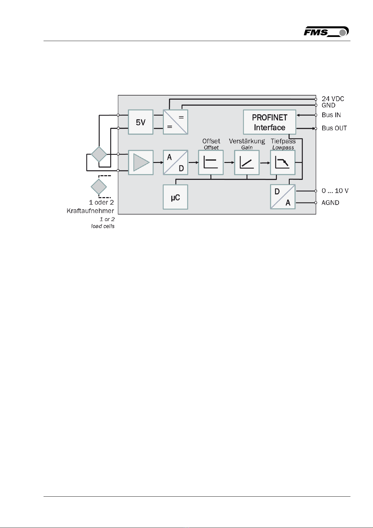
2.1 Block Diagram EMGZ490A ........................................................................................ 6
2.2 System Description EMGZ490A ................................................................................. 6
3 Quick Installation Guide ................................................................. 7
3.1 Preparations for Set-up .............................................................................................. 7
3.2 Installation Procedure ................................................................................................ 7
3.3 Installation and Wiring ............................................................................................... 7
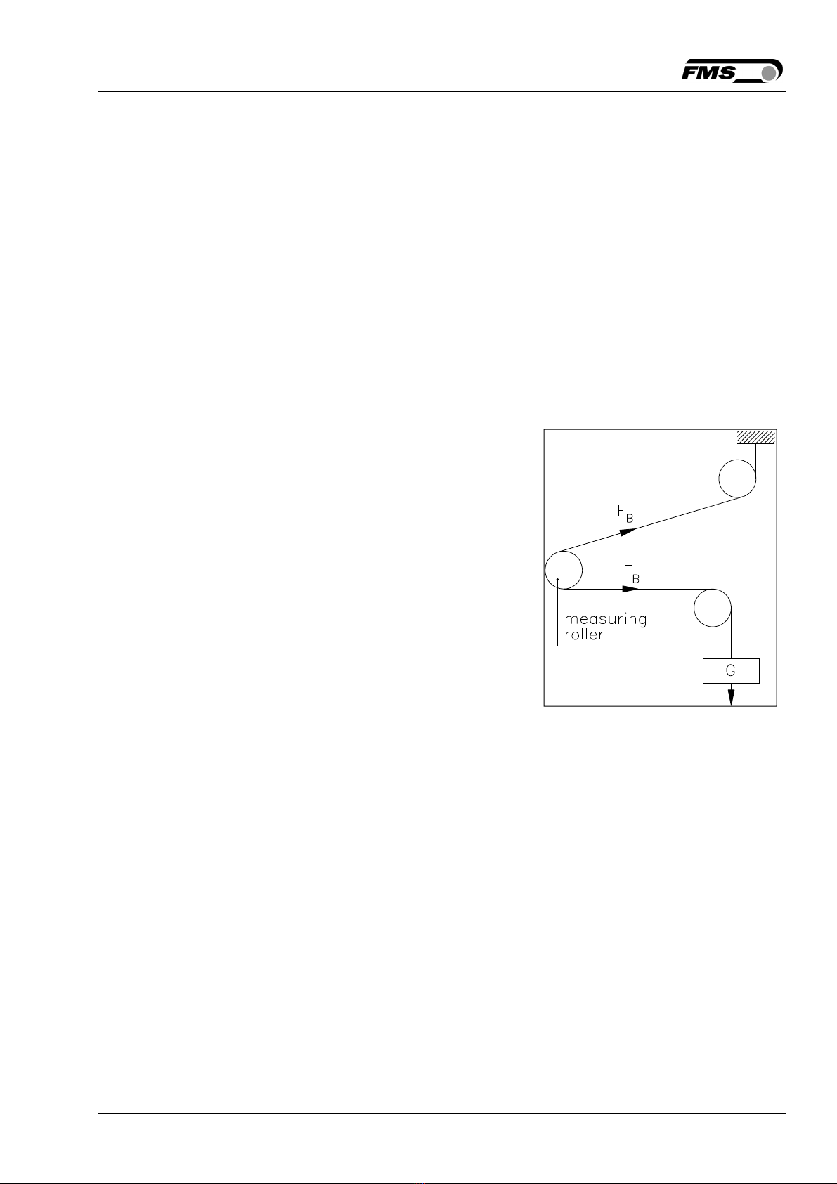
3.4 Mounting the Force Sensors ...................................................................................... 7
3.5 Wiring the Amplifier .................................................................................................... 8
4 Calibration of the Measuring System ........................................... 10
4.1 Offset Compensation ................................................................................................ 10
4.2 Calibration ................................................................................................................. 10
4.3 Calibration Procedure ............................................................................................... 11
4.4 Gain ........................................................................................................................... 12
4.5 Limit Violations ......................................................................................................... 13
4.6 Description of Signal-LEDs ....................................................................................... 14
5 Integration in a PROFINET-network .............................................. 14
5.1 PROFINET Interface ................................................................................................. 14
5.2 TCP/IP Configuration ................................................................................................ 15
5.3 System Start-up ........................................................................................................ 15
5.4 Data Exchange .......................................................................................................... 15
6 Configuration ................................................................................ 16
6.1 Description of Parameters ....................................................................................... 16
6.2 Cyclic Data Traffic ..................................................................................................... 18
6.3 Acyclic Data Traffic ................................................................................................... 19
7 PROFINET Communication ........................................................... 21
7.1 General Function ....................................................................................................... 21
7.2 Services and Protocols ............................................................................................. 21
7.3 Limitations ................................................................................................................ 22
7.4 Functional Blocks, Example ..................................................................................... 23
7.5 Data Blocks ............................................................................................................... 24
7.6 Trigger Read-/Write-instructions .............................................................................. 25
7.7 Configuration File GSDML ........................................................................................ 26
7.8 Tools ......................................................................... Fehler! Textmarke nicht definiert.
8 Web Interface ............................................................................... 27
8.1 Access to the Amplifier over a Web Interface ......................................................... 27
8.2 Parameter Setting .................................................................................................... 29

Operation Manual EMGZ490A
30.08.2019 3
8.3 Offset Compensation and Calibration via the Web Browser .................................. 30
8.4 Ethernet Settings ..................................................................................................... 31
8.5 System Settings ........................................................................................................ 32
9 Dimensions ................................................................................... 33
10 Technical Specification ................................................................. 34
10.1 PROFINET Characteristics ........................................................................................ 34
10.2 Technical Features .................................................................................................... 34
10.3 Hardware Specification ............................................................................................ 35

Operation Manual EMGZ490A
30.08.2019 4
1 Safety Instructions
All safety related regulations, local codes and instructions that appear in the manual or
on equipment must be observed to ensure personal safety and to prevent damage to
the equipment connected to it. If equipment is used in a manner not specified by the
manufacturer, the protection provided by the equipment may be impaired.
Do not stress the equipment over the specification limits neither during assembly nor
operation. To do so can be potentially harmful to persons or equipment in the event of a
fault to the equipment.
1.1 Description Conditions
a) Danger of health injury or loss of life
Danger
This symbol refers to high risk for persons to get health injury or loss life. It has to be
followed strictly.
b) Risk of damage of machines
Caution
This symbol refers to information, that, if ignored, could cause heavy mechanical
damage. This warning has to be followed absolutely.
c) Note for proper function
Note
This symbol refers to an important information about proper use. If not followed,
malfunction can be the result.

Operation Manual EMGZ490A
30.08.2019 5
1.2 List of safety instructions
Proper function of the Tension Measuring Amplifier is only guaranteed with the
recommended application of the components. In case of other arrangement, heavy
malfunction can be the result. Therefore, the installation instructions on the following
pages must be followed strictly.
Local installation regulations are to preserve safety of electric equipment. They are not
taken into consideration by this operating manual. However, they have to be followed
strictly.
Bad earth connection may cause electric shock to persons, malfunction of the total
system or damage of the electronic unit! It is vital to ensure that proper earth
connection is done.
Improper handling of the electronic boards may cause damage to the fragile
equipment! Don’t use rough tools such as screwdrivers or pliers! Operators handling
the electronic boards must wear a well earthed bracelet in order to discharge static
electricity.
In order to improve the natural convection and keep the temperature of the amplifiers
that are mounted in a cabinet, to a minimum, a distance of at least 15mm (0.6”)
between the devices must be kept.
During operation the use of not-PROFINET related services such as port scanning, web
services, load testing, and other services and protocols should be avoided. There is the
possibility of a system overload, if such a service is nonetheless used. The
consequence is a connection interruption between EMGZ490A and PLC. The
interruption usually lasts between 3-5 seconds. Afterwards, a new connection is
automatically established again.
The web interface may only be used in the test mode since data communication can
interfere with the PLC. Moreover, one link can be established via a web browser at the
same time.

Operation Manual EMGZ490A
30.08.2019 6
2 Product Description
2.1 Block Diagram EMGZ490A
Fig. 1: Block Diagram
2.2 System Description EMGZ490A
The microprocessor-controlled amplifiers of EMGZ490A series are used to amplify,
process and transmit force sensor signals to devices connected in a suitable network.
The measured force values are accessible via the PROFINET bus and on an analog
voltage output. The amplifiers are suitable for tension measurement with all FMS force
sensors. Either one or two sensors can be connected to one amplifier.
Device information, parameters or system settings can be accessed via a web browser.
Offset compensation and calibration of the system is realized through the web browser
which allows you to adjust the amplifier to the most demanding system requirements.

Operation Manual EMGZ490A
30.08.2019 7
3 Quick Installation Guide
The set-up of the EMGZ490A and force sensors is limited to only the installation procedure,
offset compensation and the calibration.
3.1 Preparations for Set-up
1. Read the Operation Manual of your force measuring sensors
2. Check your requirements such as:
– required measuring units in the system
–Used outputs (0…10V and Bus)
–Filter settings for analogue output
3. Draw the wiring diagram for your configuration (ref. to 3.5 “Wiring the Amplifier“)
3.2 Installation Procedure
1. Mount the force maesuring sensors to the machine frame (ref. to chapter 3.4)
2. Wire the Force Measuring Sensor(s) (ref. to Fig. 2)
3. Connect the amplifier to the power supply.
4. The supply voltage must in the range between 18 and 36V DC.
5. Perform offset compensation and calibration (ref. to chapters 4.1 to 4.3)
4. If required, do additional settings (chapter 8.2)
5. In tegrate the amplifier in the PROFINET-network (chapter 5)
3.3 Installation and Wiring
Caution
In order to improve the natural convection and keep the temperature of the amplifiers
that are mounted in a cabinet, to a minimum, a distance of at least 15mm (0.6”)
between the devices must be kept..
Caution
Proper function of the Tension Measuring Amplifier is only guaranteed with the
recommended application of the components. In case of other arrangement, heavy
malfunction can be the result. Therefore, the installation instructions on the following
pages must be followed strictly.
Caution
Local installation regulations are to preserve safety of electric equipment. They are not
taken into consideration by this operating manual. However, they have to be followed
strictly.
3.4 Mounting the Force Sensors
Mounting of the force sensors is done according to the FMS Installation manual which is
delivered together with the force sensors.

Operation Manual EMGZ490A
30.08.2019 8
3.5 Wiring the Amplifier
One or two force sensors can be connected to the measuring amplifier. When using two
force sensors, the sensors are internally connected in parallel. The connection between
force sensors and measuring amplifier has to be done using a 2x2x0.25mm2[AWG 23]
shielded twisted-pair cable. The cable must be installed separate from power lines.
Fig. 2a: Wiring Diagram EMGZ490A.R
Color scheme (IEC60757) and pin codes are valid for FMS components, only!
Fig. 2b: Wiring Diagram EMGZ490A.W
Color scheme (IEC60757) and pin codes are valid for FMS components, only!

Operation Manual EMGZ490A
30.08.2019 9
Fig. 2c: Ethernet Connector
Color scheme (IEC60757) and pin codes are valid for FMS components, only!
Caution
Bad earth connection may cause electric shock to persons, malfunction of the total
system or damage of the electronic unit! It is vital to ensure that proper earth
connection is done.
Note
The shield should be connected only to the electronic unit. On the force sensor side the
shield should stay open.

Operation Manual EMGZ490A
30.08.2019 10
4 Calibration of the Measuring System
The system calibration can be performed in two ways:
A) over the web interface (see chapter 8.3)
B) directly in the PLC
4.1 Offset Compensation
With the Offset Compensation one can compensate the roller weight. This procedure is
always performed before the calibration. The force measuring roller should not be
loaded while the Offset Compensation is being done.
4.2 Calibration
The Calibrating procedure (setting the Gain), adjusts
the controller and load cells so that the display gives
you the actual tension value. There are two
methods of calibrating the system. The first method
uses a defined weight. The second method is based
on a calculation method in conjunction with the
FMS Calculator. This Calculator can be down loaded
from the FMS web page. FMS recommends using
the method with the weight (see Fig. 3) since it
delivers the most accurate results.
To set the Gain, load a rope with a defined weight
on the roller. The roller configuration must
correspond to the real material path in the machine
(wrap angle, distances between the rollers etc.).
Fig. 3: Calibrating the measuring
amplifier C431011e

Operation Manual EMGZ490A
30.08.2019 11
4.3 Calibration Procedure
1. Activate web interface (ref. to chapter 8.1) and call web page „Offset/Calibration
over the web browser” (see chapter 8.3).
2. Connect volt meter to the voltage output (Fig. 2, terminal 13/14)
3. Connect first force sensor to the amplifier (see Fig. 2).
4. Check whether a load in measuring direction (red point) results in a positive volt
reading. If the reading is negative, change signal wires in the corresponding sensor
(Fig. 2, terminals 6/7).
5. If applicable, connect second force sensor.
6. Check whether a load in measuring direction (red point) results in a positive volt
reading. If the reading is negative, change signal wires in the second sensor (Fig. 2,
terminals 10/11).
7. Unload measuring roller by removing material or rope from it.
8. Click the key „Adjust Offset“.
9. Load the rope with the defined calibration weight (Fig. 3).
10. Click the key „Calibrate Gain“. With that the calibration is completed.

Operation Manual EMGZ490A
30.08.2019 12
4.4 Gain
Depending on the wrap angle of the material on the measuring roller the prevailing
force is not passed one-to-one to the sensors, with the result that the measured
material tension does not correspond to the effective force. In order to account for this
error, the measured force is amplified by multiplier (the Gain). The correction adapts the
measured force with the effective material force. The Gain Factor (V) is calculated with
following formula:
Variables:
Fsys N= Installed system force in Newton. This is determined by the number of used
force sensors in the measuring roller. With one force sensor, the system
force is equal to the nominal force mentioned on the label of the sensor. If
the measuring roller contains two sensors the force is twice as large.
Fsys Digit= System force as a binary value (max. output of A/D-converter). Here it is a
constant with the value 5945. It is independent from the number of used
sensors. From a user perspective, the value corresponds to an input signal of
9mV.
Fist N= Acting force on the measuring system in Newton.
Fist Digit= Force measured on the system as binary value (output of A/D-converter).
From a user perspective, the value corresponds to a voltage in mV, that the
amplifier will receive as an input from the force sensors.
Example:
Fsys N = 1000N; Fist N = 500N; Fist mV = 2.25mV (orr 1486)
Note
The mV values in the formula can be replaced by the binary values of the measuring
system (always 5945). The mV value (9 mV) is thus replaced by 5945. The measured
force can be determined using a voltmeter. It replaces the binary value (first digit).
This calculation method is also used by the FMS Calculator tool. Thus it is possible to use the
gain value calculated by the FMS Calculator directly in the calibration. The gain value is then
entered in the parameter set of the amplifier (see chapter 8.2 “Parameter Setting”). In this
case the calibration procedure described in chapter 4.3 can be skipped. However, FMS
recommends using the traditional method with the weight (chapter 4.2 and 4.3) since it
delivers the most accurate results.
F
sys Digit * Fist N
V =
F
sys N * Fist Digit
9mV * 500N
V = = 2.000
1000N * 2.25mV

Operation Manual EMGZ490A
30.08.2019 13
4.5 Limit Violations
The amplifier checks the analogue input and output on limit violations. It checks
whether the force sensor is mechanically overloaded (overload test). At the output, it is
checked whether the voltage output over or under shoots the physically possible value
in relation to the amplified input.
A ) Overload Test
The overload test is performed with the raw data received from A/D-converter. It is
therefore not related to a particular force and can be used regardless of the installed
system.
Test Rules:
The FMS force sensors deliver at the rated nominal force at the output 9mV.
The maximum load at the mechanical hard stop is 12.4mV. The amplifier checks the
overload in the positive measuring direction (red point) as well as in the negative
direction. The limits are therefore 12mV respectively. -12mV. Upon reaching one of
these limits, the Status Bit is set to Overload. The status Bit is reset, if the measured
value falls 0.5 mV below the limits.
B ) Overflow/Underflow Test
Over- or underflow are determined by using the output (calculated with the gain factor).
If the output exceeds the maximal possible value, there is an overflow. If it drops below
the minimal value, there is an underflow.
Test Rules:
The output voltage varies between 0 and +10 V. For the test a hysteresis of ±10 digits is
applied, in order to prevent error bits to respond at any small overflow or underflow. The
overflow is thus triggered at the output reaching the theoretically calculated value
10.05V. For the underflow applies value of -0.05V. Upon reaching one of these limits,
the corresponding Status Bits are set. The Status Bits are re-set as soon as the output
enters the range 0.05V and 9.95V.

Operation Manual EMGZ490A
30.08.2019 14
4.6 Description of LEDs
EMGZ490A.R EMGZ490A.W
LED Meaning
LNK 1 Ethernet cable 1 connected with
other station
ACT 1 Blinking, if data communication on
Ethernet connection 1 active
LNK 2 Ethernet cable 2 connected with
other station
ACT 2 Blinking, if data communication on
Ethernet connection 2 active
BF
Permanent red if no RJ45 plug is
connected
Flashes red if communication to
PLC is interrupted
SF n.c.
RDY Permanent green if power supply is
connected and processor works
Fig. 4: Signal LEDs
5 Integration in a PROFINET-network
The force measuring amplifiers of the EMGZ490A series were design to work in an
PROFINET-network whereas the amplifier acts as an IO-device (Slave) and die IO-
Controller (or PLC) as a master.
5.1 PROFINET Interface
PROFINET RT is supported. The corresponding communication profile will be selected by
the IO-controller (Master) via GSD. The EMGZ490A transmits the feedback value in Digit
and the Status/Error information Byte. In addition parameters like Offset feedback,
Gain feedback, Filter feedback, Filter analogue output and Scaling of the output can be
set.

Operation Manual EMGZ490A
30.08.2019 15
5.2 TCP/IP Configuration
In order to enable data communication between amplifier and a PLC or a web browser,
the Ethernet settings must be known. In a PROFINET-network the system designer
configures the address for each device and has therefore an overview over the
distribution of the addresses in the network. The IP-address is assigned to each device
via the PLC. The device must have an IP-address of 0.0.0.0 after power up to enable the
assignment of the final IP-address. This is the case after each EMGZ490A restart.
Static IP-address:
A static IP-address is required to enable the PLC accessing a web interface. The IP-
address of 0.0.0.0 cannot be used for this purpose, as this address is treated in a
special way according to TCP / IP–specification. Devices with this IP will not response, if
an inquiry over the web browser is started.
5.3 System Start-up
At system start-up, the communication between IO-controller (PLC) and IO-devices is
established and necessary parameters are set. The parameterisation is only performed,
if the system is accordingly configured. Otherwise, the locally stored configuration in
EMGZ490A is used. Parameters can always be changed via the web interface.
5.4 Data Exchange
The EMGZ490A uses the typical PROFINET communication methods. For rapid
transmission of the measured data cyclic data traffic is used. For the parameterisation
acyclic data traffic is used. For the transmission of limit violations also the cyclic data
traffic is used.

Operation Manual EMGZ490A
30.08.2019 16
6 Configuration
The configuration of the EMGZ490A can be performed either over a web interface or
over PROFINET. In both case the same parameters are configured.
6.1 Description of Parameters
PROFINET Filter
Use: The amplifier provides a low-pass filter for PROFINET data to prevent
noise and interferences being overlaid to the PROFINET output. This
parameter determines the cut off frequency of the filter. The lower the
cut off frequency, the more sluggish the output will be. The PROFINET
Filter is independent of the analogue output filter.
Unit Parameter Range Selection Default
Min Max
Hz 0.1 200.0 - 10.0
Analog Output Filter
Use: The amplifier provides a low-pass filter to prevent noise and
interferences being overlaid to the analogue output signal. This
parameter determines the cut off frequency of the filter. The lower the
cut off frequency, the more sluggish the signal at the analogue output
will be. The Analogue Output Filter is independent of the PROFINET Filter.
Unit Parameter Range Selection Default
Min Max
Hz 0.1 200.0 - 10.0
Tension Unit
Use: This parameter determines the unit used in the system. The label on the
sensor specifies the nominal force always in N.
Note: By changing the units to lb the whole unit system will change from metric
to imperial units.
Unit Parameter Range Selection Default
Min Max
- -
N
kN
lb
g
kg
N

Operation Manual EMGZ490A
30.08.2019 17
Tension at Max. Output
Use: This parameter defines what force value (N, kN, lb, g, kg) corresponds to
the maximum output of the amplifier (10V).
Note: By changing the units to lb the whole unit system will change from
metric to imperial units.
Unit Parameter Range Selection Default
Min Max
N, kN, g,
kg, lb(1 0 200’000.000 - 1000.000
1) The display shows the unit of measure that was previously selected.
Offset
Use: The value determined with the adjustment procedure Offset
Compensation is stored as a Digit value in the parameter Offset. The
offset value is used to compensate the weight of the measuring roller.
Unit Parameter Range Selection Default
Min Max
- -8000 8000 - 0
Gain
Use: This parameter stores the value determined with the Procedure
Calibration in the parameter Gain.
Unit Parameter Range Selection Default
Min Max
0.100 20.000 - 1.000
System Force
Use: The System Force determines the measuring capability of your
measuring roller. E.g. if two 500 N sensors are installed in your
measuring roller, enter 1000N. If only one 500N sensor is used, enter
500N. If sensors with sheaves are used (e.g. RMGZ-Series), 500N must
be entered.
Unit Parameter Range Selection Default
Min Max
N, kN, g,
kg, lb(1 0 200’000.000 - 1000.000
1) The display shows the unit of measure that was previously selected..

Operation Manual EMGZ490A
30.08.2019 18
6.2 Cyclic Data Traffic
After a successful system boot the IO-controller and associated IO-devices can start
exchanging cyclic process data. The following table shows which data are transmitted and in
which form.
Cyclic Data
User Data Data Type Range Format Unit Description
Feedback
Value in ADC
int
(signed 16
Bit)
-32768
to
32767
±#0 - Fetched value form A/D-
converter
Feedback
Value in
Newton
signed long
(signed 32
Bit)
±200‘000‘000 ±#0.000 N Filtered feedback value
re-calculated in Newton
Feedback
Value in
Pound
signed long
(signed 32
Bit)
±200‘000‘000 ±#0.000 lb Filtered feedback value
re-calculated in Pounds
Feedback
Value in Unit
signed long
(signed 32
Bit)
±200‘000‘000 ±#0.000 N,
kN,
g, kg
lb
Filtered feedback value
re-calculated in the
configured unit
Status byte
(unsigned 8
Bit)
- - -
The status includes
information about the
current process or
operating mode. Each bit
represents a separate
event. The condition is
active, if the bit is set
Bit 0 = Overload (LSB)
Bit 1 =Output Overflow
Bit 2 =Output Underflow

Operation Manual EMGZ490A
30.08.2019 19
6.3 Acyclic Data Traffic
After a successful system boot the IO-controller and associated IO-devices can start
exchanging acyclic data. The table below shows which parameters and instructions are
transmitted.
Index
Access Mode 1)
Parameter
Instruction
Data
Type Range
Data Format
Unit
Description
0x01 R Device-ID unsigned
int
(unsigned
16 Bit)
0
to
65535
#0 - Request
Device Type
0x02 R Version unsigned
int
(unsigned
16 Bit)
1
to
10000
#0.00 - Request
Firmware Version
0x10 R/W Low pass filter
feedback
active(PROFIN
ET)
byte
(unsigned
8 Bit)
0
bis
1
0 - Switch filter
on/off
0 = off; 1 = on
Non-remanent:
the set value will
be lost after each
re
-
start
0x11 R/W Low pass filter
Analogue
Output active
byte
(unsigned
8 Bit)
0
to
1
0 - Switch filter
on/off
0 = off; 1 = on
Non-remanent:
the set value will
be lost after each
re
-
start
0x20 R/W Offset int
(signed 16
Bit)
±8‘000 #0 - Offset
0x21 R/W Gain unsigned
int
(unsigned
16 Bit)
0
to
20000
#0.000 - Gain
0x22 R/W System Force unsigned
long
(unsigned
32 Bit)
0
to
200‘000‘000
#0.000 N The system force
is the maximum
permissible force
in the measuring
system

Operation Manual EMGZ490A
30.08.2019 20
Index
Access Mode 1)
Parameter
Instruction
Data
Type Range
Data Format
Unit
Description
0x23 R/W Scaling
Analogue
Output
unsigned
long
(unsigned
32 Bit)
0
to
200‘000‘000
#0.000 N Determines at
which force the
analog output
reaches its
maximal value of
10V
0x24 R/W Cut-off
frequency low
pass filter
feedback
(PROFINET)
unsigned
int
(unsigned
16 Bit)
1
to
2000
#0.0 Hz Cut-off frequency
of PROFINET filter
0x25 R/W Cut-off
frequency low
pass filter
Analogue
output
unsigned
int
(unsigned
16 Bit)
1
to
2000
#0.0 Hz Cut-off frequency
of analogue
output filter
0x30 W Offset
compensation
- - - - Calculate offset
and store value
0x31 W Calibration signed
long
(signed 32
Bit)
±200‘000‘000 ±#0.00
0
N Calibrate the
amplifier with
weight in N (must
correspond with
the used weight
for calibration).
1) R = read, W = write, R/W = read and write.
Table of contents
Other FMS Amplifier manuals