Oval TF1015-P11G-11 A Series User manual

1
MASS FLOW MONITOR
MODEL:TF10□□- P11
A12 G-11□A□
Every OVAL Mass Flow Monitor is fabricated and shipped from our factory under stringent quality
control.
In order to maintain its design performance throughout its life, this manual offers the operator the necessary
installation, operation and maintenance information.
Be well familiar with these instructions before you place the product in service and keep this manual at the
field location for ready reference.
Ins. No. S-193-11-E
TF1015-P11G-11□A□
TF1020-P11G-11□A□
TF1025-A12G-11□A□
TF1040-A12G-11□A□
TF1050-A12G-11□A□

S-193-11-E
2
CONTENTS
1. BEFORE YOU BIGIN ............................. 3
1.1 Confirming the Nameplate ......................... 3
1.2 Transportation Considerations................... 3
1.3 Storage Considerations.............................. 3
2.OPERATING CONDITIONS ................... 4
3.GENERAL .............................................. 4
3.1 Features ...................................................... 4
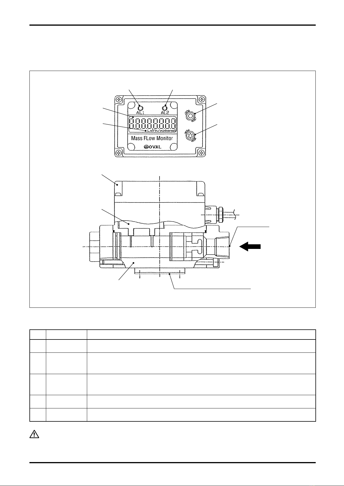
4.COMPONENT NAMES AND
FUNCTIONS .......................................... 5
4.1 Part Names................................................. 5
4.2 Individual Functions ................................... 5
5.INSTALLATION ...................................... 6
5.1 Installation Location.................................... 6
5.2 Physical Orientation ................................... 6
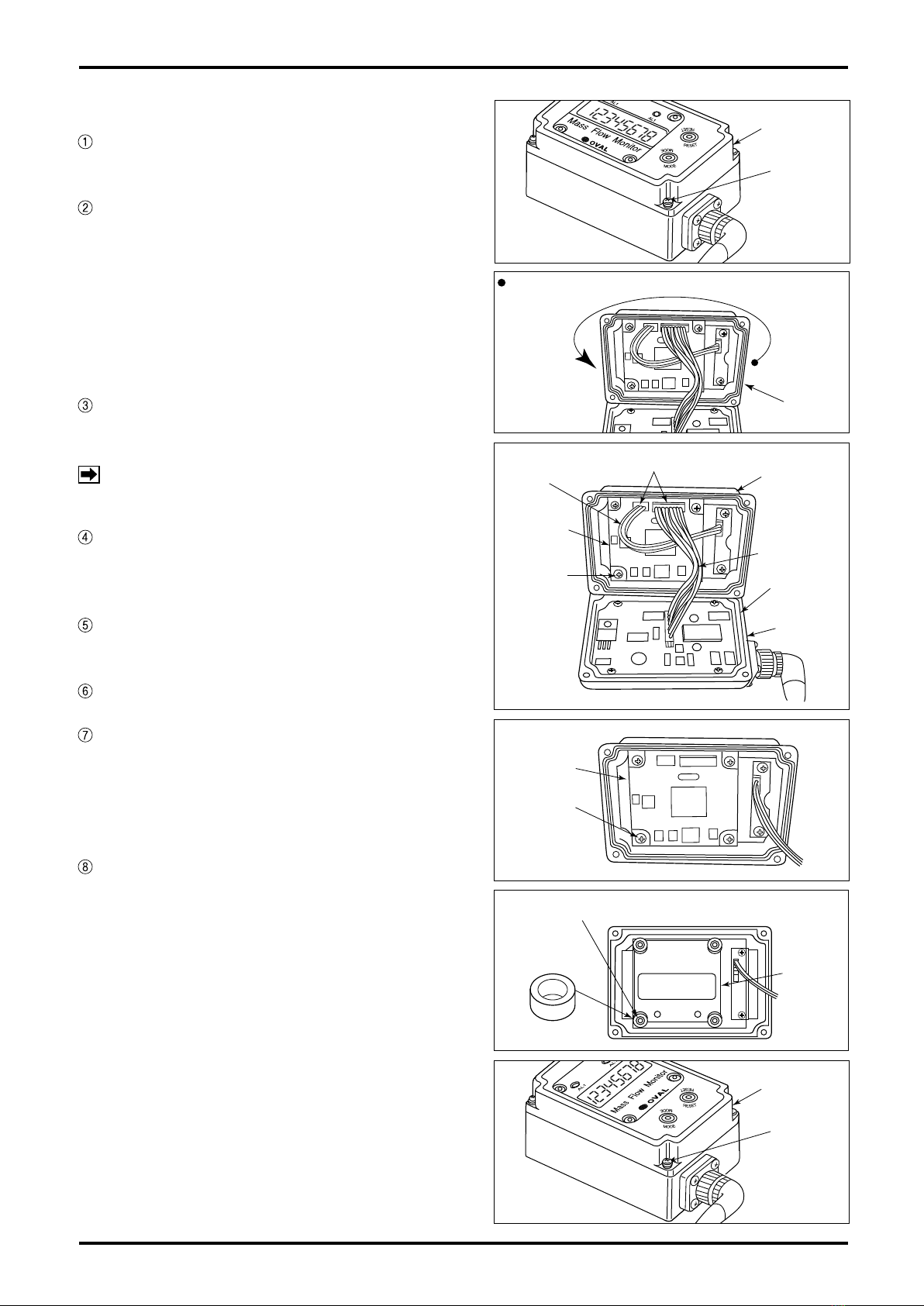
5.3 How to Change Display Orientation ........... 6
5.4 Conditions Required for Metered Fluid ...... 8
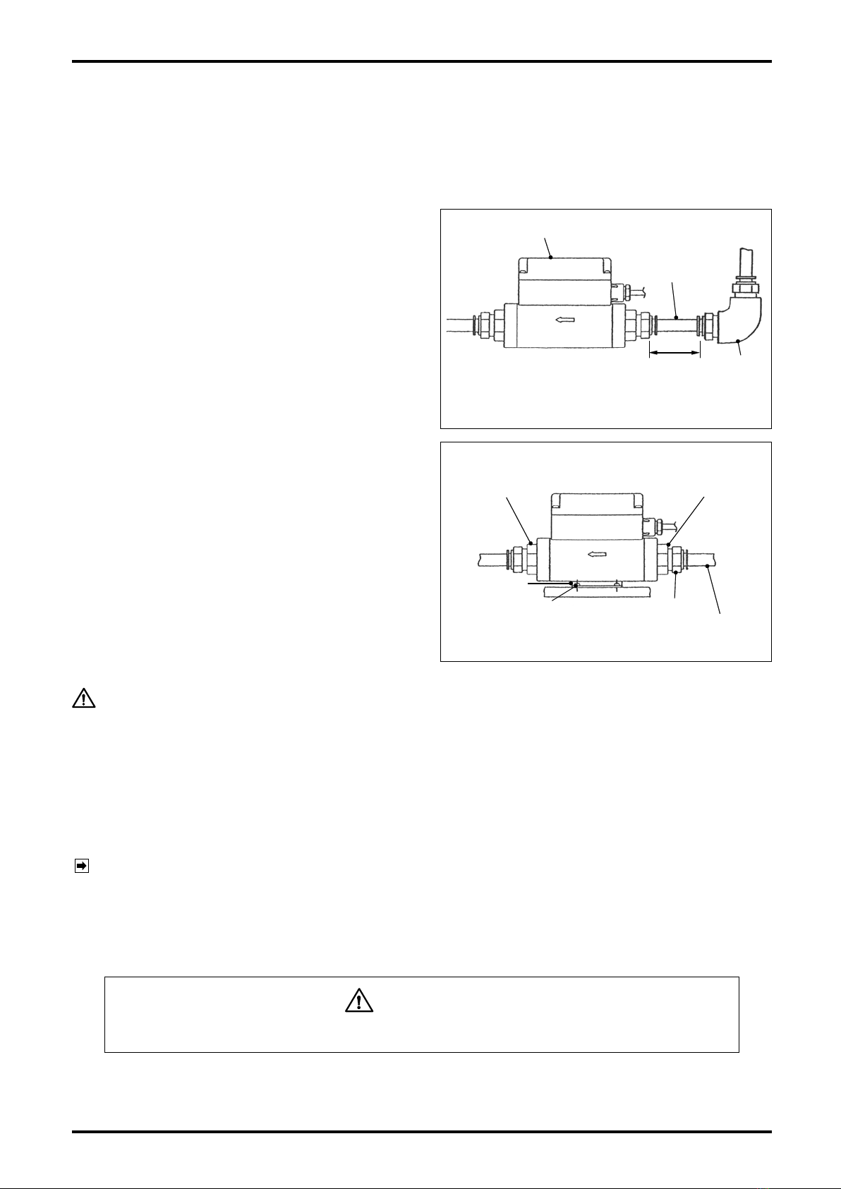
5.5 Tubing Guidelines....................................... 8
5.6 Maximum Service Flowrate........................ 9
6. WIRING CONNECTIONS ..................... 10
6.1 Wiring Specifications .................................10
6.2 Wiring Diagram..........................................10
6.3 Cable Specifications .................................14
7. OPERATION ........................................ 14
8.TRANSMITTER DISPLAY FUNCTIONS
AND RECONFIGURATION .................. 15
8.1 Viewing the Flow Variables ........................15
8.2 Parameter Display .....................................16
8.3 Default Parameter Settings .......................18
8.4 Parameter Reconfiguration .......................19
8.5 Alarm Features .........................................20
8.6 Dummy Pulse Output ................................24
8.7 Analog Output Trim ...................................25
8.7.1 Analog Trim (4mA) ....................................... 25
8.7.2 Analog Trim (20mA) ..................................... 26
8.8 Error Messages .........................................27
9. GENERAL SPECIFICATIONS ............. 28
10. APPLICABLE STANDARDS.............. 28
11. PRODUCT CODE EXPLANATION .... 29
12. OUTLINE DIMENSIONS....................30
CONVENTIONS
Shown in this manual are the signal words NOTE, CAUTION and WARNING, as
described in the examples below:
NOTE: Notes are separated from the general text to bring the user's attention
to important information.
CAUTION: Caution statements signal the user about hazards or unsafe practices
which could result in minor personal injury or product or property
damage.
WARNING: Warning statements signal the user about hazards or unsafe practices
which could result in severe personal injury or death.

S-193-11-E
3
1. BEFORE YOU BIGIN
Every OVAL product is thoroughly inspected and tested before it leaves the factory. When received, it should
be thoroughly inspected for indication of rough handling during transit. Necessary handling precautions are
described in this section; read the instructions carefully.
As for other information, find the respective sections from "CONTENSTS" on page 2.
For any inquiries, contact your nearest OVAL designated sales office.
CAUTION: When you make inquiries, include the product name, model number, stock
number, ratings and other pertinent information.
1.1 Confirming the Nameplate
Every OVAL monitor is carefully assembled and
accurately adjusted to first-class condition. Product
code number and ratings appear on the nameplate. By
referring to the general specifications in Section 9 and
product code explanation in Section 11, make sure
that the product you received is fully in compliance
with your order.
1.2 Transportation Considerations
(1) It is desirable that the monitor be transported to the installation site in the shipping container used for
transit from the factory.
(2) During transportation, exercise care to avoid impact shock and rainwater.
1.3 Storage Considerations
Storing your mass flow monitor for long periods of time upon receipt before installation can result in
unexpected and undesirable conditions. When long-term storage is anticipated, take the following
precautions:
(1) The monitor can best be stored in the shipping container used for transit from the factory.
(2) Select the storage place that meets the following requirements:
★free from rain and water
★free from vibration and impact shocks
★with least temperature and humidity variation (around 25°C and 65% R.H).
(3) A monitor that has once been placed in service for any length of time should be washed clean to remove
residue of metered material completely from its main body, joint, conduit, and outer case before storage.
Especially, purge the inner wall of flow path with clean air or nitrogen gas, and then protect the flow inlet
and flow outlet against entry of dust inside.
CAUTION: 1. At cleansing, do not use solvents, such as thinner and alcohol.
2. Never attempt to cleanse the interior flow path with detergent.
Nameplate
(ratings shown)

S-193-11-E
4
2. OPERATING CONDITIONS
The monitor operating conditions are stated on the specification label, Section 5 "INSTALLATION" and Section
9 "GENERAL SPECIFICATIONS." Read carefully before initiating operation.
CAUTION: This monitor is of non-explosionproof configuration; it is not serviceable in a
hazardous location.
3. GENERAL
This monitor is a small, lightweight flowmeter, using a
heat-sensitive resistance element.
Of the two heat-sensitive resistance elements located
perpendicular to the fluid flow; one detects the fluid
temperature and the other, which plays the role of
a heater, regulates the temperature of the former to
maintain a constant temperature differential. As the
flowing process fluid (mass flow) dissipates heat
from the latter which serves as a heater, its supply
power increases in order to maintain the temperature
differential. This change in power consumption (voltage
and current) is used to calculate the mass flowrate.
3.1 Features
(1) Absence of moving parts contributes to long life.
(2) Major components are made of synthetic resin. Lightweight and compact.
(3) Sturdy metallic couplings.
(4) The display is a backlit LCD for readability in darkness.
(5) May be installed in any position. The display can be oriented in 90 deg steps to see easily.
CAUTION: Adjusting the display orientation requires opening the upper case of transmitter.
The procedure to change orientation appears in Section 5.3 "How to Change
Display Orientation".
Fig. 3.1
Heat-sensitive
resistance elements
Flow direction

S-193-11-E
5
Fig. 4.1
Alarm 1 LED
LCD display
(Unit indicator)
⑤RESET button
④MODE button
Screw
connection
Alarm 2 LED
Flow direction
③Transmitter
①Monitor body
②Sensor
Mounting hardware (option)
4. COMPONENT NAMES AND FUNCTIONS
4.1 Part Names
4.2 Individual Functions
No. Part Name Description
①Body Consists of a measuring tube, straightener, and rectification mesh.
②Sensor
Consists of two heat-sensitive resistance elements. Power supply (voltage and current)
to one of the heat-resistive resistance elements changes to maintain the heat resis-
tance at a constant level (approx. 30°C).
③Transmitter
Changes in supply power (voltage and current) are transformed into a flowrate signal
which can be monitored on a 8-digit LCD display in terms of instant flowrate and total
flow.
④Mode button Changes display modes to the instant flowrate or total flow. (See Sec. 8.1 for details.)
⑤Reset button Used to reset the "Resettable total flow" to zero.
CAUTION: Do not attempt to disassemble the meter. If the flow path is badly contaminated
or a malfunction is suspected, contact the nearest customer service network in
your area. Unauthorized disassembly will void the warranty.

S-193-11-E
6
Fig. 5.1
Standard
(at shipment from factory)
90°to the right
Flow Direction
180°
90°to the left
5. INSTALLATION
5.1 Installation Location
This monitor is for indoor use.
Select an installation location that meets the requirements set forth below.
CAUTION: This monitor is NOT serviceable in a hazardous location.
(1) Free from rain and water.
(2) Least temperature variation.
(3) Free from direct exposure to the sun.
(4) Least vibration and impact shock.
(5) Easy to read the display and accessible for servicing.
(6) Process condition to keep fluid pressure not to exceed the permissible pressure of 0.7 MPa.
5.2 Physical Orientation
There is no restriction on physical orientation of the monitor to cause loss of the accuracy.
Make sure that the actual flow direction conforms to the flow direction arrow indicated on the monitor body.
NOTE: The display orientation can be adjusted in 90 deg steps to see easily (see Section 5.3).
5.3 How to Change Display Orientation
This work is done with the transmitter subassembly removed. Observe the following instructions:
(1) Work in a clean environment before installing the monitor in the tubing system.
(2) Avoid working in a moist or dusty environment.
(3) Exercise care to avoid damaging the components on the electronics substrate while you work.
Required tools: Screwdrivers (for M3 and M2.6 cross recess pan head screws).
Display orientation is adjustable in 90 deg steps as shown below:

S-193-11-E
7
How to Change Display Orientation
If power is supplied, shut it off. (Make sure
nothing appears on the LCD).
Take off four set screws (3×14) securing the
upper case to the transmitter and carefully
open the upper case (Fig. 5.2).
If a 180 deg. turn is your option, turn the upper
case the other way with lead wires intact (Fig.
5.3).
To turn 90 deg. clockwise or counterclockwise
follow the steps given below.
Take off four set screws (2.6×8) holding the
display board in place and remove the display
board (Fig. 5.5).
Remove four spacers (white rings) attached to
the bosses that have secured the display board
in place (Fig. 5.6).
Extract the top panel and put it onto the upper
case then in the different orientation.
Install the removed spacers over the bosses.
Place the display board in line with the top
panel and secure it with four screws (2.6×8
with tightening torque 45cN・m). (Align the
opening in the top panel with the mating LED
on the display board).
Make certain that O-ring fits in the groove
of lower case and, exercising care against
pinched cables, secure the upper case with
four screws (3×14 with tightening torque of
60cN・m). Tighten them in an alternating order
to ensure even tightening (Figs. 5.7).
Display
Board
Fig. 5.5
Setscrew
(4 PLC'S)
Fig. 5.4
3-wire
Cable
Display
Board
Setscrew
(4 PLC'S)
Upper Case
10-wire Cable
O-Ring
Cable Connectors
Lower
Case
Fig. 5.3
Turn the upper case 180°, with cables intact.
Upper
Case
Fig. 5.7
Upper Case
Setscrew
(4 PLC'S)
Fig. 5.2
Upper Case
Setscrew
(4 PLC'S)
Top Panel
Bosses (4 PLC'S)
Spacer
(4 PLC'S)
Fig. 5.6
NOTE: Do not take out the screws fixing amp
board on lower case in any case.

S-193-11-E
8
5.4 Conditions Required for Metered Fluid
Due to the fact that this monitor is a thermal flowmeter, contamination buildup can cause loss of accuracy. In
an environment where entrapment of contaminants, such as dust, oil, and water, is anticipated, it is a good
practice to provide a filter, drain, separator or similar arrangement upstream of the monitor.
5.5 Tubing Guidelines
(1) Required Tubing Conditions
Since the monitor has a built-in straightener,
tubing conditions, such as differences in tube
diameter, for example, rarely present a problem.
However, if an elbow is to be located upstream
of the monitor, provide a straight tube about the
length of a nipple (3D min.). Direct installation of
an elbow may possibly cause an error of ±1 %
F.S. or so.
There is no restriction on tubing arrangements
downstream of the monitor.
(2) Installation of mounting hardware (option for
meter sizes 15mm and 20mm).
Required tool: Torque screwdriver that fits M3
cross recess pan head screws.
Do not use any other accessories except for the
furnished dedicated screws (tap-tight screws
3 x 8). See outline dimensions in Sec. 12 for
Installation location and orientation.
Torque specification: 60±3 cN・m
Elbow
Fig. 5.8
30 min.
Monitor body
Straight tube
D: Meter I.D.
CAUTION: With metal tubes, tubing stresses could damage the flowmeter at its metal
fittings. Do not use the mounting hardware with metal tubes. Instead, secure
the metal tubes with U-bolts or similar fittings.
(3) Tube Connection Procedure (for meter sizes 15mm and 20mm)
1. Connecting parts are of aluminum die casting: avoid forcibly installing them and giving an impact
shock. The monitor body is of synthetic resin: avoid applying stresses on it. Torque specification: 30 ±
1 (N・m)
NOTE: Hold the hexagonal flats of aluminum die cast connection firmly with wrench, or similar tool, when
you work (Fig. 5.9).
2. Use care to safeguard the transmitter from coming in contact with tools, such as wrench.
3. Do not hold the transmitter by force while connecting it to the tubing system.
4. Providing a union before and after the flowmeter is suggested to facilitate flowmeter removal.
Negligence of the precautions above may result in damaged components.
(4) Flushing
If foreign solids are expected to get into the tubing system, particularly on a new installation, flushing of
the tubing assembly thoroughly is essential before installing the monitor.
Quick-connect coupling
Meter Fitting
Synthetic resin tube
Mtg. Hardware
Meter fitting
Fig. 5.9
Screw
WARNING

S-193-11-E
9
■Line pressure vs. maximum service flowrate (nominal sizes 25mm, 40 and 50mm)
9000
8000
7000
6000
5000
4000
3000
2400
2200
2000
1000
0
0 0.1 0.2 0.3 0.4 0.5 0.6 0.7
0.240.11
Line pressure [MPa]
Max. service flowrate [L/min (normal)]
Nominal size 40 mm
Nominal size 50 mm
Nominal size 25 mm
900
800
700
600
500
400
300
200
100
0
0 0.1 0.2 0.3 0.4 0.5 06 0.7
0.04
Line pressure [MPa]
Max. service flowrate [L/min (normal)]
Nominal size 20 mm
Nominal size 15 mm
■Line pressure vs. maximum service flowrate (nominal sizes 15mm and 20mm)
5.6 Maximum Service Flowrate
The maximum service flowrate varies with line pressure. Measurement continuation at larger service flowrates
may possibly damage the sensor. Therefore, determine the maximum service flowrate from the following
graphs and place the sensor in service within the rate so obtained.

S-193-11-E
10
1: SUP (power +)
4: Flow pulse output
3: COM (power-)
GND
Shieldedwire
ConnecttheshieldedwiretoGND.
BRN:SUP(power+)
WHT:Alarm1output
YEL:Flowpulseoutput
GRN:COM(power-)
max.
30VDC,
20mADC
max.
30VDC,
20mADC
24VDC±10%
BRN:SUP(power+)
2: Alarm 1 output
Connector terminal
1
3
42
WHT:Alarm1output
BLK:Flowpulseoutput
BLU:COM(power-)
max.
30VDC,
20mADC
max.
30VDC,
20mADC
24VDC±10%
●Cable (OMRON)
●Cable (OVAL)
Model: XS2F-D42□-□80-F
Note: For cables, refer to the following figures.
• When product code "Output terminal" is [2] or [4], OVAL cable is supplied.
• When product code "Output terminal" is [3] or [5], cable must be prepared by the customer.
In this case, OMRON cable is recommended.
25 cm
3m
6. WIRING CONNECTIONS
6.1 Wiring Specifications Table 6.1
Item Description
Transmission cable
(Depends on your
specification).
The following cables are supplied depending on the 15th digit of the product code.
[1]: 5-conductor shielded cable of 3 meters long (O.D.: 6.3mm) ... Fixed to this
unit.
[2][4]: 4-conductor shielded cable of 3 meters long (O.D.: 6.3mm, 4-pin connector is
provided at the one side of the cable) ... Supplied with this unit.
Alarm output
Open collector output
Allowable current: 20mADC
Max. voltage impression: 30VDC
Flow pulse output
Open collector output
Allowable current: 20mADC
Max. voltage impression: 30VDC
Flow analog output 4 to 20mA corresponding to 0 to F.S.
Supply Voltage 24VDC±10%
6.2 Wiring Diagram
NOTE: For output terminal types and styles, see "Explanation of Output Terminal Types" below NOTES in
Sec. 11.
CAUTION: 1. Use extra care about the polarities of power source.
2. Do not fail to earth ground the shielded wire to GND.
(1) Flow pulse output + single alarm point specifications (Fig. 6.1)
●Connector terminal ●Connector via interconnect cable
Fig. 6.1

S-193-11-E
11
1: SUP (power +)
4: Alarm 1 output
3: COM (power -)
GND
Shieldedwire
ConnecttheshieldedwiretoGND.
BRN:SUP(power+)
WHT:Flowanalogoutput
YEL:Alarm1output
GRN:COM(power-)
max.
30VDC,
20mADC
4to20mA
max.
500Ω
4to20mA
max.
500Ω
24VDC±10%
BRN:SUP(power+)
2: Flow analog output
Connector terminal
1
3
42
WHT:Flowanalogoutput
BLK:Alarm1output
BLU:COM(power-)
max.
30VDC,
20mADC
24VDC±10%
●Cable (OMRON)
●Cable (OVAL)
Model: XS2F-D42□-□80-F
Note: For cables, refer to the following figures.
• When product code "Output terminal" is [2] or [4], OVAL cable is supplied.
• When product code "Output terminal" is [3] or [5], cable must be prepared by the customer.
In this case, OMRON cable is recommended.
25 cm
3m
(2) Flow analog output + one alarm specifications (Fig. 6.2)
●Connector terminal ●Connector via interconnect cable
Fig. 6.2

S-193-11-E
12
GND
Shieldedwire
ConnecttheshieldedwiretoGND.
BRN:SUP(power+)
WHT:Flowanalogoutput
YEL:Flowpulseoutput
GRN:COM(power-)
max.
30VDC,
20mADC
4to20mA
max.
500Ω
4to20mA
max.
500Ω
24VDC±10%
BRN:SUP(power+)
Connector terminal
1
3
4
2
WHT:Flowanalogoutput
BLK:Flowpulseoutput
BLU:COM(power-)
max.
30VDC,
20mADC
24VDC±10%
Model: XS2F-D42□-□80-F
25 cm
3m
1: SUP (power +)
4: Alarm 1 output
3: COM (power -) 2: Flow analog output
●Cable (OMRON)
●Cable (OVAL)
Note: For cables, refer to the following figures.
• When product code "Output terminal" is [2] or [4], OVAL cable is supplied.
• When product code "Output terminal" is [3] or [5], cable must be prepared by the customer.
In this case, OMRON cable is recommended.
(3) Flow pulse output + flow analog output specifications (Fig. 6.3)
Fig. 6.3
●Connector terminal ●Connector via interconnect cable

S-193-11-E
13
GND
Shieldedwire
ConnecttheshieldedwiretoGND.
BRN:SUP(power+)
WHT:Alarm1output
YEL:Alarm2output
GRN:COM(power-)
max.
30VDC,
20mADC
max.
30VDC,
20mADC
24VDC±10%
BRN:SUP(power+)
Connector terminal
1
3
4
2
WHT:Alarm1output
BLK:Alarm2output
BLU:COM(power-)
max.
30VDC,
20mADC
max.
30VDC,
20mADC
24VDC±10%
Model: XS2F-D42□-□80-F
25 cm
3m
1: SUP (power +)
4: Alarm 1 output
3: COM (power -) 2: Flow analog output
●Cable (OMRON)
●Cable (OVAL)
Note: For cables, refer to the following figures.
• When product code "Output terminal" is [2] or [4], OVAL cable is supplied.
• When product code "Output terminal" is [3] or [5], cable must be prepared by the customer.
In this case, OMRON cable is recommended.
(4) Two alarm point specifications (Fig. 6.4)
Fig. 6.4
●Connector terminal ●Connector via interconnect cable

S-193-11-E
14
3m
GRY:Alarm1output
YEL:Flowpulseoutput
WHT:Alarm2output
BRN:SUP(power+)
GRN:COM(power-)
max.
30VDC,
20mADC
max.
30VDC,
20mADC
max.
30VDC,
20mADC
24VDC±10%
GND
Shieldedwire
ConnecttheshieldedwiretoGND.
(5) Flow pulse output + two alarm points specifications (Fig. 6.5)
(6) Flow pulse output + flow analog output + single alarm point specifications (Fig. 6.6)
GRY:Alarm1output
YEL:Flowpulseoutput
WHT:Flowanalogoutput
BRN:SUP(power+)
GRN:COM(power-)
max.
30VDC,
20mADC
max.
30VDC,
20mADC
4to20mA
max.
500Ω
24VDC±10%
GND
Shieldedwire
ConnecttheshieldedwiretoGND.
3m
Fig. 6.6
CAUTION: If "Without cable" is specified for the product, the cable shown in the wiring diagram
is not supplied with the product.
6.3 Cable Specifications
Applicable cable depends on the specifications of the 15th digit "Output Terminal" of the product code. Refer
to the following table.
Fig. 6.5
●Direct coupled cable
15th digit of
product code
"Output Terminal"
specifications ※1Cable Specifications State at shipment from factory
「1」Cable coupled directly
[OVAL cable]
5-conductor shield cable
Length: 3 m, O.D.: 6.3 mm
Directly coupled to the product body.
「2」Connector via
interconnect cable
(with cable) [OVAL cable]
4-conductor shield cablewith connector
Length: 3 m, O.D: 6 mm
Packed together with product body.
「4」Connector terminal
(with cable)
「3」Connector via
interconnect cable
(without cable)
[Recommended cable]
Manufacturer: OMRON
Model: XS2F-D42□-□80-F
Name: Cabled connector socket single side connector
Length: As specified by the customer
O.D.: 6 mm
Cable is not supplied with the product.
To be prepared by the customer. The ca-
ble shown on the left is recommended.
(Purchase the cable directly from the
manufacturer.)
「5」Connector terminal
(without cable)
7. OPERATION
(1) Verify that the process fluid conditions (such as pressure and temperature) meet the ratings specified.
(2) After confirming the wiring connections, turn on power and see that the flowrate reads zero.
(3) Making sure there is no leaks at tube connections, carefully open the upstream valve.
CAUTION: 1. Just after powering on, this equipment is ready for measurement. However, the optimum
accuracy is available 30 minutes after power on.
2. To safeguard the monitor against damage, avoid sharp increase in flowrate.
※1 For the kind and shape of the output terminal, refer to the section "Explanation of Output Terminal".

S-193-11-E
15
Yen converted instant.
Flowrate (hourly)
Accumulated total
Instant. flowrate (hourly)
Instant. flowrate
(per-min)
Resettable total
Yen converted accum.
total
Yen converted
resettable total
Press MODE .
Press MODE .
Press MODE .
X
.
X
.
X
.
X
.
X
.
X
.
X
.
X
X
.
X
.
X
.
X
.
X
.
X
X
.
X
.
X
.
X
.
X
.
X
X
.
X
.
X
.
X
.
X
.
X
.
X
X
.
X
.
X
.
X
.
X
.
X
.
X
X
.
X
.
X
.
X
.
X
.
X
X
.
X
.
X
.
X
.
X
.
X
....................
....................
....................
....................
....................
....................
....................
Press MODE .
Press MODE .
Press MODE .
Press MODE .
8. TRANSMITTER DISPLAY FUNCTIONS AND RECONFIGURATION
8.1 Viewing the Flow Variables
The flow monitor can show seven flow variables, one at a time.
With each depression of the "MODE" button, the display scrolls through available variables as shown in the
diagram below. Keep on pressing the "MODE" button until the variable desired appears.
(Immediately after powerup, the display shows the most recently selected variable before power was turned
off. "X" in each box at left represents a numerical value of the variable).
Menu item Description
Accumulated
total flow
Indicates the total flow accumulated until now.
(The accumulated total is not resettable to "0".)
Reads in m3(normal).
Instant
flowrate
(hourly)
Indicates the per-minute instant flowrate.
Reads in m3/h (normal).
Instant
flowrate
(per-minutes)
Indicates the hourly instant flowrate.
Reads in L/min (normal).
Resettable
total flow
Indicates the total flow that has flown since the last RESET op-
eration. (Pressing the "RESET" button while total reset flow is
displayed sets the total flow to "0".)
Reads in m3(normal).
Accumulated
total flow in
terms of Yen
※1
Accumulated total flow in terms of Yen which is the product of
flowrate and Yen conversion factor.
Reads in Yen. (Unit of registration is not shown.)
Instant
flowrate in
terms of Yen
(hourly) ※1
Instant flowrate in terms of Yen which is the product of flowrate
and Yen conversion factor.
Reads in Yen/h.
(Only /h appears for the unit of registration.)
Resettable
total flow in
terms of Yen
※1
Resettable total flow in terms of Yen which is the product of
flowrate and Yen conversion factor.
Reads in Yen. (Unit of registration is not shown.)
Indicates the total flow that has flown since the last RESET op-
eration. (Pressing the "RESET" button while the resettable total
flow in terms of Yen appears resets this reading to "0".)
NOTE ※1:By establishing the Yen value per unit fluid volume of 1m3(normal) to the
Yen conversion factor, the monitor can show accumulated total, instant
flowrate, and resettable total, each in terms of Yen.
(When "0" is set to the Yen conversion factor, the accumulated total, instant
flowrate, and resettable total, each in terms of Yen, will not appear. Factory-
set default Yen conversion factor is "0".)

S-193-11-E
16
8.2 Parameter Display
Alarm-related parameters are shown on the left half; remaining parameters and special functions are on the
right half of the diagram. To change parameters, scroll through menu items until the parameter you want to
change is shown before you make necessary changes.
To restore flow variables, hold the "MODE" button depressed for 5 seconds either at, ALA , or bdAtA window.
Flow variables (accum. total, instant flowrate, resettable total and accum, total, instant. flowrate, resettable total, each in terms of Yen)
Press MODE for 5 sec.
Press RESET .
Alarm 1 hysteresis
Alarm menu
....................
Press MODE .
Alarm 1 setpoing
Alarm 1 status
Press RESET .
Alarm 2 setpoing
Alarm 2 hysteresis
Alarm 2 status
Low alarm dead zone
Alarm dead duration
Menu item Description
Alarm 1
setpoint
Alarm 1 setpoint.
Beyond this setpoint, an alarmed condition takes place. (During
the time of alarm dead zone, alarm output and LED indication
remain inactive, however).
Set the flowrate to activate an alarm.
Setpoint reads in L/min (normal).
Alarm 1
hysteresis
Alarm 1 hysteresis.
If flowrate fluctuation is excessive, causing frequent alarm ON-
OFF trips, select a larger value.
Setpoint reads in L/min (normal).
Alarm 1
status
Alarm I status setpoint.
By selecting either code of the following to the upper digit, you
can set up the type of errors to be identified.
H: High alarm L: Low alarm
By setting either code of the following, you can set up the sta-
tus of open collector output in an error.
o: OFF in an error S: ON in an error
Alarm 2
setpoint
Alarm 2 setpoint.
The functions remain the same as Alarm 1 setpoint.
Alarm 2
hysteresis
Alarm 2 hysteresis.
The functions remain the same as Alarm I hysteresis.
Alarm 2
status
Alarm 2 detailed status setting.
The functions remain the same as alarm 1 status.
Low alarm
dead zone
The lower limit to activate an alarm. Below this flowrate, alarm
remains inoperative even if alarm conditions are met.
Reads in L/min (normal).
Alarm dead
duration
Delay time of identifying an alarm. Any alarm condition does
not activate an alarm at once; only after the expiration of this
duration.
Read in seconds.
X
.
X
.
X
.
X
.
X
X
.
X
.
X
.
X
.
X
X
.
X
X
.
X
.
X
.
X
.
X
X
.
X
.
X
.
X
.
X
X
.
X
....................
....................
....................
....................
....................
....................
X
.
X
.
X
.
X
.
X
X
.
X
....................
Press MODE .
Press MODE .
Press MODE .
Press MODE .
Press MODE .
Press MODE .
Press MODE .
Press MODE .

S-193-11-E
17
To view parameters of interest, hold the "MODE" button depressed for 5 seconds at the flow variables
window to show ALA window. The diagram below will lead you the rest of the way using the "MODE" and
"RESET" buttons until the parameter desired appears.
("XXX" in each box at left represents a numerical value of the variable).
NOTES: 1. See Sec. 8.3 for acceptable parameter setting
range and factory set defaults.
2. ※1: Models not provided with an analog
output do not show these menu items.
Basic data menu
Press MODE for 5 sec.
Yen conversion
factor
Full scale flowrate
All figure places
illuminated
Zeroing
Damping time
Press MODE .
Dummy output
Pulse weight
Pulse ON width
Cutoff
Analog trim (4mA)
Analog trim (20mA)
Menu item Description
Yen
conversion
factor
A parameter to perform conversion to obtain Yen equivalent. Yen
equivalent represents the cost per unit flow of 1 m3(normal) of me-
tered process fluid.
Reads in Yen/m3(normal).
When set to "0", Yen conversion does not take place.
Pulse weight Unit flowrate per single output pulse.
Reads in L (normal).
To change the setpoint, be sure to meet the following conditions. Un-
less these conditions are satisfied, proper pulse output is not pro-
duced.
Max. service flowrate [L/min (normal)] / pulse weight
[L(normal)] x (pulse "ON" [msec] + 1) / 60 < 1000
Pulse ON
width
Output pulse width.
Reads in msec.
Unless the same conditions as those of pulse weight are satisfied,
proper pulse output is not produced.
Cutoff Instantaneous flowrate cutoff setpoint.
Any flow below this flowrate reads "0".
Reads in L/min (normal).
Dummy
output
A 10Hz pulse output is available irrespective of the flowrate curently
in measurement. You can use this feature in verifying the connections
with other system, or for other purpose. (For the procedure of produc-
ing dummy output, see Sec. 8.6 "Dummy Pulse Output".)
Analog Full
scale flowrate
※1
Flowrate at analog output full scale (20mA).
Analog
Damping time
※1
Sets damping time for analog output. (Due to inherent circuit proper-
ties, approx. 1 sec time const. exists besides software setting.)
Reads in sec.
Analog trim
(4mA)
※1
Trims analog output of 4mA.
(For details, see Sec. 8.7 "Analog Output Trim".)
Analog trim
(20mA)
※1
Trims analog output of 20mA.
(For details, see Sec. 8.7 "Analog Output Trim".)
Zeroing Adjusts the zero baseline. The product is shipped after calibration in
the factory. Normally, the product does not require Zero baseline ad-
justment.
To adjust, press ahd hold the "MODE" button for more than 5 sec-
onds while pressing the "RESET" button in this mode.
Backlight
setting
You can select any one of four backlight activation modes.
On: Illuminated full time, EC: Illuminated full time at the half level of
illumination at On time, OF: Always unlit, SL: Illumination darkened to
half approx. 10 sec. after completing button operation.
All figure
places
illuminated
This feature is useful in testing the illumination of LCD display and
alarm LED indicator lamps.
Illuminates all LCDs and alarm LEDs.
(Alarm output appears as usual.)
X
.
X
.
X
.
X
.
X
.
X
.
X
X
.
X
.
X
.
X
.
X
.
X
X
.
X
.
X
X
.
X
.
X
.
X
.
X
.
X
X
.
X
.
X
.
X
X
.
X
.
X
.
X
.
X
X
.
X
.
X
.
X
.
X
Press MODE .
Press MODE .
Press MODE .
Press MODE .
Press MODE .
Press MODE .
Press MODE .
Press MODE .
Press MODE .
Press MODE .
Press MODE .
X
.
X
.
X
....................
....................
....................
....................
....................
....................
....................
....................
....................
....................
....................
....................
Press MODE .
Backlight setting
X
.
X

S-193-11-E
18
Top row: Parameter name
Middle row: Unit of numerical value
Bottom row: Settable range
Factory default settings
Nominal size
15mm 20mm 25mm 40mm 50mm
Alarm 1 setting
L/min (normaI)
0 to 99999
50 65 200 400 650
Alarm 1 hysteresis
L/min (normal)
0 to 99999
10 15 35 85 135
Alarm 1 status
Ho, HS, Lo, LS
LS LS LS LS LS
Alarm 2 setting
L/min (normal)
0 to 99999
600 800 2200 5000 8000
Alarm 2 hysteresis
L/min (normal)
0 to 99999
10 15 35 85 135
Alarm 2 status
Ho, HS, Lo, LS
HS HS HS HS HS
Low limit in alarm immunity range
L/min (normal)
0 to 99999
10 15 35 85 135
Alarm immune time
Seconds
0 to 99
33333
Yen conversion factor
Yen 1m3(normal)
0 to 999.999
2.000 2.000 2.000 2.000 2.000
Pulse weight
L (normal)
0.01 to 9999.99
0.1 0.1 1.00 1.00 1.00
Pulse width
msec
1 to 240
55553
Cutoff ※1
L/min (normal)
0 to 99999
9 14 34 84 134
Analog full scale
L/min (normal)
0 to 99999
600 800 2200 5000 8000
Analog Damping
sec
0 to 99
00000
Backlight setting
On, EC, OF, SL
On On On On On
8.3 Default Parameter Settings
Parameters are set to the following default settings before shipment from the factory:
NOTES: ※1: Cutoff set value must not be changed in other than the following cases.
(1) When output is given though the flow is stopped (※).
Set the cutoff value a little greater than the output value at that time.
(2) When you want to measure the flowrate of the area lower than the cutoff value, set the
cutoff value lower than the desired flowrate.
Under some condition, the difference at this area may be greater depending on the offset
value of the zero point. Therefore, adjust zero point while the flow is stopped (※) as
necessary.
※The stoppage of flow refers to the status where the valve at the lower stream of this unit is
fully opened under the process condition in use and there is no leakage from the valve.

S-193-11-E
19
8.4 Parameter Reconfiguration
An example below shows the procedure to change Alarm 2 setting from 600 to 500.
For display operating procedure, see Section 8.2 "Parameter Display".
Press MODE for 2 sec.
Press RESET 9 times.
Press MODE for 2 sec.
600
600
600
500
500
....................
....................
....................
....................
....................
Description
[Show the alarm 2 setting.]
Hold the "MODE" button depressed for more than 2 seconds. When the screen
begins to blink, remove your finger from the button.
(Write mode becomes active and the figure in the ones place blinks.)
[The figure "0" in the right-most place blinks.]
Press the "MODE" switch twice to allow the digit in the hundreds place to blink.
(Pressing the "MODE" button moves the blinking digit one place to the left).
["6" in the hundreds place blinks.]
Press the "RESET" button 9 times to adjust the figure to 5.
(Pressing the "RESET" button increases the blinking figure.)
[The digit in the hundreds place changes to "5" while blinking].
Now the reading has been changed to 500.
To save this value, hold the "MODE" button depressed for more than 2 seconds.
When the screen begins to blink, remove your finger from the button. (The
setting is saved and you exit the write mode.)
If you want to exit the write mode without completing the setting, hold the
"RESET" button depressed for more than 2 seconds. When the screen begins
to blink, remove your finger from the button. (You exit the write mode without
saving any value.)
[The indicator stops blinking and stays on.]
Now the setup process is complete.

S-193-11-E
20
8.5 Alarm Features
In this monitor, settings of alarms 1 and 2 are adjustable to any levels to help you keep on monitoring the
process flow. And by setting up two parameters - "lower limit in alarm immunity range" and "alarm immunity
time," precise alarm settings can be established against leaks. Follow the instructions given in this manual
when you set up alarm set points. Examples of alarm setup are also given in this section.
CAUTION: If alarm features are not desired, set the alarm set points to "0" (alarm status
either at high alarm or lower alarm).
(1) Setting up the high alarm
Parameters related to the high alarm come in the following five, (1) through (5). Set each of them by
referring to the description given for individual parameters.
①Alarm setpoint
Set the flowrate [(L/min (normal)) to be at the upper alarm.
②Alarm hysteresis
Alarm is cancelled when the following conditions are met. Select the appropriate alarm hysteresis [L/
min (normal)].
Flowrate < Alarm setpoint - Alarm hysteresis
If variation in flowrate is excessive, resulting in frequent alarm ON-OFF cycling, set a little larger value.
③Alarm status (higher digit)
Setting is to be made on the high alarm: set "H" to the higher digit.
④Alarm status (lower digit)
Set up the output status to the lower digit in an alarmed condition.
Selecting "S" results in an "ON" output (Lo impedance) in an alarmed condition.
Setting "o" results in an "OFF" (Hi impedance) in an alarmed condition.
⑤Alarm immunity time
Set the delay time [in sec] from the moment the flowrate exceeds the alarm set value to the moment
an alarm is activated. Remember that setting of this parameter is common to both alarms 1 and 2.
This manual suits for next models
4
Table of contents