Oxford Semiconductor OX16PCI952 User manual

Oxford Semiconductor Limited
25 Milton Park
Abingdon
Oxfordshire
OX14 4SH, UK
(44) 1235 824900
http://www.oxsemi.com
OX16PCI952
Evaluation Board
User Guide
UG-0013 May 05
StockCheck.com

ii External—Free Release UG-0013 May 05
OX16PCI952 Evaluation Board User Guide
© Oxford Semiconductor Limited 2005
The content of this manual is furnished for informational use only, is subject to change without notice, and should not
be construed as a commitment by Oxford Semiconductor Limited. Oxford Semiconductor Limited assumes no
responsibility or liability for any errors or inaccuracies that may appear in this book.
All trademarks are the property of their respective owners
StockCheck.com

UG-0013 May 05 External—Free Release iii
Contents . . . . . . . . . . . . . . . . . . . . . . . . . . . . . . . . . . . . . . . . . . . . . . . . . . . . . . . . . . . . . . . iii
Preface . . . . . . . . . . . . . . . . . . . . . . . . . . . . . . . . . . . . . . . . . . . . . . . . . . . . . . . . . . . . . . . . .v
Revision Information . . . . . . . . . . . . . . . . . . . . . . . . . . . . . . . . . . . . . . . . . . . . . . . . . v
Typographic Conventions . . . . . . . . . . . . . . . . . . . . . . . . . . . . . . . . . . . . . . . . . . . . . v
Product Details . . . . . . . . . . . . . . . . . . . . . . . . . . . . . . . . . . . . . . . . . . . . . . . . . . . . .vi
Contacting Oxford Semiconductor . . . . . . . . . . . . . . . . . . . . . . . . . . . . . . . . . . . . . .vi
Chapter 1 Evaluation Board Overview . . . . . . . . . . . . . . . . . . . . . . . . . . . . . . . . . . . . . .1
Features . . . . . . . . . . . . . . . . . . . . . . . . . . . . . . . . . . . . . . . . . . . . . . . . . . . . . . . . . .1
Configuration . . . . . . . . . . . . . . . . . . . . . . . . . . . . . . . . . . . . . . . . . . . . . . . . . . . . . . .1
Drivers . . . . . . . . . . . . . . . . . . . . . . . . . . . . . . . . . . . . . . . . . . . . . . . . . . . . . . . . . . . .2
Board Layout . . . . . . . . . . . . . . . . . . . . . . . . . . . . . . . . . . . . . . . . . . . . . . . . . . . . . . .2
Chapter 2 Evaluation Board Features . . . . . . . . . . . . . . . . . . . . . . . . . . . . . . . . . . . . . .5
Jumpers . . . . . . . . . . . . . . . . . . . . . . . . . . . . . . . . . . . . . . . . . . . . . . . . . . . . . . . . . . .5
Headers & Connectors . . . . . . . . . . . . . . . . . . . . . . . . . . . . . . . . . . . . . . . . . . . . . . .6
Chapter 3 Configuring the Evaluation Board . . . . . . . . . . . . . . . . . . . . . . . . . . . . . . . . .7
Device Modes . . . . . . . . . . . . . . . . . . . . . . . . . . . . . . . . . . . . . . . . . . . . . . . . . . . . . .8
EEPROM Configuration Using OxProm . . . . . . . . . . . . . . . . . . . . . . . . . . . . . . . . . .9
Selecting Clocks . . . . . . . . . . . . . . . . . . . . . . . . . . . . . . . . . . . . . . . . . . . . . . . . . . . .9
Drivers . . . . . . . . . . . . . . . . . . . . . . . . . . . . . . . . . . . . . . . . . . . . . . . . . . . . . . . . . . . .9
Interrupts . . . . . . . . . . . . . . . . . . . . . . . . . . . . . . . . . . . . . . . . . . . . . . . . . . . . . . . . .10
Contents
StockCheck.com

iv External—Free Release UG-0013 May 05
Contents OX16PCI952 Evaluation Board User Guide
Appendix A Drivers . . . . . . . . . . . . . . . . . . . . . . . . . . . . . . . . . . . . . . . . . . . . . . . . . . . . . 11
Driver Process . . . . . . . . . . . . . . . . . . . . . . . . . . . . . . . . . . . . . . . . . . . . . . . . . . . . .11
Using the Serial Driver . . . . . . . . . . . . . . . . . . . . . . . . . . . . . . . . . . . . . . . . . . . . . . 12
Using the Parallel Port Driver . . . . . . . . . . . . . . . . . . . . . . . . . . . . . . . . . . . . . . . . . 14
Appendix B RS422 & RS232 Connector Pin Assignment . . . . . . . . . . . . . . . . . . . . . . 17
RS422 Connector Pins . . . . . . . . . . . . . . . . . . . . . . . . . . . . . . . . . . . . . . . . . . . . . . 17
RS232 Connector Pins . . . . . . . . . . . . . . . . . . . . . . . . . . . . . . . . . . . . . . . . . . . . . . 17
DB9-to-DB25 Converter . . . . . . . . . . . . . . . . . . . . . . . . . . . . . . . . . . . . . . . . . . . . . 18
RS232 Loop-Back Test Plugs . . . . . . . . . . . . . . . . . . . . . . . . . . . . . . . . . . . . . . . . 19
RS232 Null Modem Cables . . . . . . . . . . . . . . . . . . . . . . . . . . . . . . . . . . . . . . . . . . 20
RS232 monitor cable . . . . . . . . . . . . . . . . . . . . . . . . . . . . . . . . . . . . . . . . . . . . . . . 21
Appendix C Customizing the Device Vendor ID & Subsystem ID . . . . . . . . . . . . . . . . 23
Overview . . . . . . . . . . . . . . . . . . . . . . . . . . . . . . . . . . . . . . . . . . . . . . . . . . . . . . . . 23
Examples . . . . . . . . . . . . . . . . . . . . . . . . . . . . . . . . . . . . . . . . . . . . . . . . . . . . . . . . 24
Appendix D Troubleshooting . . . . . . . . . . . . . . . . . . . . . . . . . . . . . . . . . . . . . . . . . . . . . 27
StockCheck.com

UG-0013 May 05 External—Free Release v
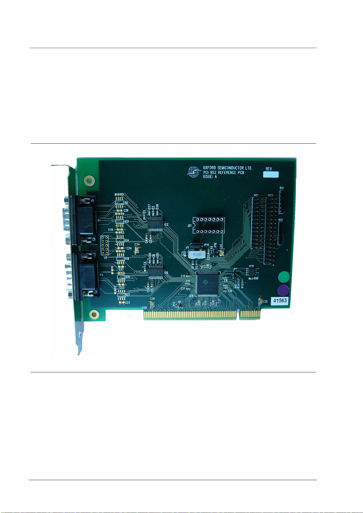
The OX16PCI952 evaluation board provides an environment in which
the various modes and features of the OX16PCI952 device can be
demonstrated.
This guide documents the board and explains how to use it to develop
systems using the Oxford Semiconductor OX16PCI952 device. It is
relevant to developers working on implementations using those
products and should be read before using it, to avoid the possibility of
usage errors.
This manual assumes that you understand the capabilities of Oxford
Semiconductor bridge and UART products, and are familiar with PCI
and PC card bus interfaces.
Revision
Information Table I documents the revisions of this manual
Typographic
Conventions In this manual, the conventions listed in Table II apply.
Table I Revision Information
Revision Modification
Jan 2005 First publication in revised house style
May 2005 Graphics modification
Table II Typographic Conventions
Convention Meaning
Italic Letters With Initial Capital Letters A cross-reference to another publication
Courier Font Software code, or text typed in via a keyboard
Bold Letters A program, function, class, or method
1, 2, 3 A numbered list where the order of list items is significant
A list where the order of items is not significant
“Title” Cross-refers to another section within the document
Significant additional information
Preface
StockCheck.com

vi External—Free Release UG-0013 May 05
Preface OX16PCI952 Evaluation Board User Guide
Product
Details The order code for the OX16PCI952 evaluation board is EV-OX16PCI952.
Contacting
Oxford
Semiconductor
Oxford Semiconductor contact details:
Oxford Semiconductor Ltd.
25 Milton Park
Abingdon
Oxfordshire
OX14 4SH
United Kingdom
Website: http://www.oxsemi.com
Telephone: +44 (0) 1235 824900
Fax: +44 (0) 1235 821141
Email: [email protected]
Alternatively, you can contact your local representative.
StockCheck.com

UG-0013 May 05 External—Free Release 1
Evaluation Board
Overview
The OX16PCI952 evaluation board kit contains the OX16PCI952
evaluation board with embedded OX16PCI952 chip.
Board documentation, standard configuration files and utility tools such
as OxProm are available from the Oxford Semiconductor website.
Features The evaluation board is an adaptable tool with configurable features
including the following:
Configurable device modes
Parallel port function via a standard 25-way D-type header
Serial EEPROM socket for maximum device configurability
Internal crystal oscillator, or any frequency via a TTL oscillator
socket (switchable)
Configuration The evaluation board is a valuable tool for assessing the behavior of the
OX16PCI952 device and can be configured to support systems using the
following selectable capabilities:
2-port serial (1 × RS232, 1 × RS422)/1-port parallel card
2-port serial (1 × RS232, 1 × RS422)
Chapter 3 Configuring the Evaluation Board explains the board settings
required to operate the OX16PCI952 in these modes.
Chapter 1
StockCheck.com

2External—Free Release UG-0013 May 05
Evaluation Board Overview OX16PCI952 Evaluation Board User Guide
Drivers The drivers provided for the OX16PCI952 evaluation board have been
written for Windows 2000, Windows NT and Windows XP operating
systems. Contact Oxford Semiconductor for details of drivers written for
Linux and other operating systems.
For further information about device drivers, see Appendix A Drivers.
Board Layout Figure 1 shows the OX16PCI952 evaluation board.
Figure 1 OX16PCI952 Evaluation Board
Note: the example shown above illustrates a 2 × RS232 configuration
Figure 2 on page 3 identifies the principal features on the device.
StockCheck.com

UG-0013 May 05 External—Free Release 3
OX16PCI952 Evaluation Board User Guide Evaluation Board Overview
Figure 2 OX16PCI952 Evaluation Board Features
For greater detail, a reference schematic for the OX16PCI952 evaluation
board can be requested from Oxford Semiconductor.
Chapter 2 Evaluation Board Features gives further details about the
features of the OX16PCI952 evaluation board.
IC9
OXPCI952
JP15 JP16
Y1 JP1
IC10
HD1 HD2
EEPROM
PCI Edge Connector
9-Way D Type
Serial Connector
9-Way D Type
Serial Connector
Parallel Connectors
JS1 Crystal
Oscillator
Socket
J2
StockCheck.com

4External—Free Release UG-0013 May 05
Evaluation Board Overview OX16PCI952 Evaluation Board User Guide
This page is intentionally blank
StockCheck.com

UG-0013 May 05 External—Free Release 5
Evaluation Board
Features
The OX16PCI952 evaluation board contains a variety of sockets, jumpers,
connectors and headers, which enhance its flexibility.
Jumpers Table 1 details the jumpers on the board and their use.
Note:
1 If this is fitted, a TTL crystal oscillator must be connected to JS1.
2 Delivers backward compatibility with 16C550, 16C650 and 16C750 devices.
3 The FIFO size of each UART may also be set to 128 by setting the UART's FCR [5] when LCR [7] is set,
or by putting the device into enhanced mode. The unlatched state of this pin is readable by software.
Table 1 Jumpers on the OX16PCI952 Evaluation Board
Jumper Use Selection
JP1 Selects the device mode Not fitted(as supplied)—2 serial ports/1parallel port
Fitted—2 serial ports
JP15 Selectstheoscillatortype
for the OX16PCI952 TTL oscillator (as supplied)(1)
Internal oscillator
JP16 Selects the FIFO depth Not fitted—16(2)
Fitted—128(3)
Chapter 2
StockCheck.com

6External—Free Release UG-0013 May 05
Evaluation Board Features OX16PCI952 Evaluation Board User Guide
Headers &
Connectors The OX16PCI952 evaluation board has the following headers and
connectors:
HD1 & HD2—parallel port headers
P1 & P2—9-way D-type serial connectors
P3B—PCI edge connector
J2—DTR/DSR header for RS422
J2
Figure 3 shows J2, which is the 5×2 DTR/DSR header for the RS422
channel on the evaluation board.
The OX16PCI952 supports one RS422 port. Data transfer rates are much
greater using RS422 protocol, because it uses differential signalling.
However, RS422 connectors only allow for CTS/RTS flow control. J2
provides access to the hardware lines necessary to provide DTR/DSR
flow control in addition to conventional CTS/RTS flow control.
Figure 3 J2
RS422 connection via a 9-way D connector is documented in Appendix B
RS422 & RS232 Connector Pin Assignment.
P1 & P2
On the evaluation board, P1 & P2 are 9-way D-type serial connectors
used to access the PCI UART serial ports. Appendix B RS422 & RS232
Connector Pin Assignment documents the serial connectors more fully.
DTR1-
DTR1+
DTR0-
DTR0+
NC
DSR1-
DSR1+
DSR0-
DSR0+
GND
1
StockCheck.com

UG-0013 May 05 External—Free Release 7
Configuring the
Evaluation Board
The OX16PCI952 evaluation board can be used to verify system designs
utilizing up two serial ports and a parallel port. The mode depends on
the mode pin settings on the board. In addition to the mode pins, other
jumpers control clock and FIFO depth selection.
The configuration process determines which driver is used to operate a
configured device, using a system of unique vendor and subsystem IDs
to differentiate modes. The IDs used for the primary device modes
covered in this chapter are hard-coded and should not be changed.
However, the OX16PCI952 is flexible and can be used for other solutions,
which require their own IDs. Appendix C Customizing the Device
Vendor ID & Subsystem ID outlines recommended procedures for
reconfiguring the hardware drivers to identify custom add-in card
configurations.
This chapter does not cover baud rate configuration for the device. For
further details of how to set the device transfer rate, refer to the
application note OXAN15 Setting Baud Rates Under Windows.
Chapter 3
StockCheck.com

8External—Free Release UG-0013 May 05
Configuring the Evaluation Board OX16PCI952 Evaluation Board User Guide
Device
Modes Header JP1 on the OX16PCI952 evaluation board is used to select the
device mode. The location of JP1 is shown in Figure 2 on page 3.
Selecting the Device Mode
Table 2 shows how the mode pins are used to select the device mode.
Implementing Mode 0—Two Serial Ports/Parallel Port
In dual UART/parallel port mode, two UARTs are provided using the
OX16PCI952 and one of the parallel port headers is used. The key
settings for implementing this mode are listed below:
JP1 must be set to 00
Connect the parallel port header to HD1 or HD2
For the UARTs, channel 1 interfaces via RS232 connections and channel 2
interfaces via RS422 connections. The RS422 ports apply flow control
using an extra cable to implement DTR and DSR signals that are enabled
via J2. Although it is possible to obtain basic hardware flow control
without DTR and DSR, they are essential for DTR/DSR flow control or
isochronous mode operation.
The following jumpers can be fitted according to user requirements:
JP15—clock selection
JP16—FIFO depth
Implementing Mode 01—Two Serial Ports Only
In dual UART mode, setting JP1 to 00 selects only the UARTs on the
OX16PCI952. For the UARTs, channel 1 interfaces via RS232 connections
and channel 2 interfaces via RS422 connections. The RS422 ports apply
flow control using using an extra cable to implement DTR and DSR
signals that are enabled via J2. Although it is possible to obtain basic
hardware flow control without DTR and DSR, they are essential for
DTR/DSR flow control or isochronous mode operation.
The following jumpers can be fitted according to user requirements:
JP15—clock selection
JP16—FIFO depth
Table 2 Mode Pin Settings & Effect
JP1 Setting Device Mode
0 2 serial ports & 1 parallel port
1 2 serial ports only
StockCheck.com

UG-0013 May 05 External—Free Release 9
OX16PCI952 Evaluation Board User Guide Configuring the Evaluation Board
Implementing One Serial/One Parallel Port
Although the standard device modes for the OX16PCI952 use two serial
ports, it is possible to configure only one, with a parallel port if required,
which illustrates the flexibility of the device.
To implement only one serial port, unzip the distributable drivers as
directed and edit the file oxpci.inf file: find the section:
[PCI_9521.NT.HW.AddReg]
HKR,, "OxsemiDeviceType", 0x00010001,0x95210000
Add a line, so that the modified section is:
[PCI_9521.NT.HW.AddReg]
HKR,, "OxsemiDeviceType", 0x00010001,0x95210000
(New line) HKR,, "OxsemiPortCount",0x00010001,1
Then insert the card in the PC and follow the driver installation process
(see Appendix A Drivers for details). Use the Windows device manager
to confirm that the port(s) have been properly installed and run a loop-
back test to text that the serial port works correctly.
EEPROM
Configuration
Using
OxProm
The OX16PCI952 can be configured via a serial EEPROM if required,
using the Oxford Semiconductor OxProm EEPROM programming
utility. All features of the device can be programmed using OxProm,
which can be downloaded from the Oxford Semiconductor website.
OxProm is bundled with reference drivers, sample configuration files
and supporting documentation including the Oxford Semiconductor
OxProm EEPROM Programming User Guide, which explains how to
program the OX16PCI952 using OxProm.
To configure the OX16PCI952 via its EEPROM, plug the EEPROM into
IC10 on the evaluation board. If the EEPROM has not previously been
programmed, it presents the value 0xFF when OxProm is used to
program it.
Selecting
Clocks An external clock must always be connected to XT1 for the PCI UARTs.
Either an internal crystal oscillator or a TTL oscillator module can be
used; the JP15 jumper setting specifies the type of oscillator supplied. See
Chapter 2 Evaluation Board Features for more about this jumper setting.
See the Oxford Semiconductor OxProm EEPROM Programming User Guide
for details of how to use OxProm.
Drivers The device operational mode determines which driver is loaded. For
detailed instructions on how to install the reference drivers, see
Appendix A Drivers.
StockCheck.com

10 External—Free Release UG-0013 May 05
Configuring the Evaluation Board OX16PCI952 Evaluation Board User Guide
Interrupts Interrupts in PCI systems are level-sensitive and can be shared. In the
OX16PCI952, there are five interrupt sources—one from each UART
channel, two from multi-purpose I/O pins (MIO0 and MIO1), and one
from the parallel port.
Note:
1 The OXPCI952 has only two interrupt pins, INTA# and INTB#. Interrupts are not asserted if a function
generates values other than 1 or 2.
Table 3 OX16PCI952 Interrupt Sources
Interrupt Pin Field Value Interrupt Pin
0 None
1INTA#
2INTB#
3 to 255 Reserved
StockCheck.com

UG-0013 May 05 External—Free Release 11
Reference drivers and utilities for the Oxford Semiconductor UART
products are supplied to demonstrate functionality under Windows
operating systems. These drivers have been tested using Oxford
Semiconductor development boards in a range of PC systems.
Driver software and any accompanying files are provided ‘as is’ and
without warranties as to performance or merchantability, or any other
warranties whether express or implied.
Driver
Process Windows driver architectures are very similar, utilizing Plug and Play
bus drivers which create device objects for each available UART and
parallel port. New driver installation commences when the configured
device is connected to the PC, although subsequent actions can vary
slightly depending on the operating system. For Windows systems other
than Windows NT4, the driver installation process is as follows:
1 Each UART is hooked by a single-port driver, which enables the
following features:
128-byte receiver & transmitter FIFOs
Adjustable receiver & transmitter interrupt trigger level
Automatic flow control
Quad speed—using the Times clock register (TCR)
Flexible baud rate generation up to 15 Mbaud
RS485 half-duplex configuration
Memory-mapped operation (Windows 2000 driver only)
2. The local bus/parallel port is hooked to the generic driver
supplied with Windows.
The drivers automatically recognize the device in any of its default or
standard configurations.
In Plug and Play systems, a wizard automatically starts up when a new
device is detected, to assist with device management. Although it is
necessary to direct the wizard to the location of the driver files, the
wizard handles device and driver installation automatically.
For more help with device installation, see the Windows Help facility.
Drivers
StockCheck.com

12 External—Free Release UG-0013 May 05
Drivers OX16PCI952 Evaluation Board User Guide
Using the
Serial Driver The serial drivers are highly configurable. They make use of a number of
enhanced features for the Oxford Semiconductor 950-series UARTs.
This section describes the configuration utilities that can be used to
enable and configure driver features. It assumes that you are using a
Win 2K or Windows XP operating system. However, Oxford
Semiconductor also provides additional drivers for the OX16PCI954 as
follows:
Drivers for Win 9xand Windows ME, which are similar to
Win 2K and Windows XP drivers
Win NT4 driver, which is a single non-Plug and Play driver with
limited configuration options
For further details about any of these drivers, contact Oxford
Semiconductor.
The driver automatically installs the correct number of serial ports, to
which the Windows operating system assigns COM numbers (e.g.,
COM5). You can then attach modems etc. to the ports and use them in
the same way as any other generic port. However, extra configuration
options are available in addition to the standard settings tab supplied
with generic drivers. Follow the steps below to adjust the UART serial
parameters:
1 Display the Control Panel and select the device manager (if nec-
essary, consult the Windows help facility for details of how to do
this).
2. Ensure that the Devices by type viewing option is selected.
3. Click the +by Ports (COM & LPT) to review the installed PCI
COM ports.
4. Double-click the appropriate Oxford Semiconductor PCI COM
port to display its properties dialog.
Three tags in the dialog are used to configure enhanced device features:
Settings—for standard COM port settings
Data rate—advanced data rate selection options
FIFOs—device mode selection and FIFO trigger level settings
Settings
The Settings tag groups the standard baud rate, data bits, parity, stop bits
and flow control options for standard COM port settings. The settings
modify the defaults used by Windows, although most applications that
use COM ports override the settings with their own parameters.
An application’s baud rate is scaled up if a faster crystal is used.
StockCheck.com

UG-0013 May 05 External—Free Release 13
OX16PCI952 Evaluation Board User Guide Drivers
This tag also allows users to select RS232, RS422, or RS485 half-duplex
operation. The following points are worth noting for these options:
For RS232 applications the DTR pin should be configured as
normal
For RS485, the driver can configure the DTR pin as either active-
high or active-low
DTR/DSR flow control is not allowed for RS422/485, because
these pins are not defined in RS422 protocols
Data Rate
The Data Rate dialog is used to set the clock frequency and baud rate.
For normal operation, the serial driver generates the baud rate from the
crystal frequency. The baud rate can optionally be adjusted as required.
Click Detect Crystal Frequency to detect the input clock frequency to the
UART, otherwise select the frequency from the Crystal Frequency
(MHz) drop-down box.
For automatic crystal detection, no other application can be using the
port.
On initial entry to this dialog, the Use default baud rate check box is
checked; unchecking it enables the following options for overriding the
port configuration:
Baud rate multiplier—checking this box allows you to select a
value from the drop-down box to scale up the baud rate
Quad speed—checking this box results in all application-selected
baud rates being multiplied by four
Baud rate divider (prescaler)—checking this box allows you to
select a value from the drop-down box to scale down the selected
baud rate
Using the facilities in this dialog box, a high speed crystal can be pre-
divided to generate standard baud rates or scaled up to allow higher
data rates.
FIFOs
The FIFOs dialog is used to configure 950 mode, which operates with full
128-byte FIFOs, fully adjustable trigger levels and thresholds for
generating interrupts and applying automatic flow-control. This dialog
can also disable the FIFOs completely, although it is not recommended
for normal operation.
Clicking the Use FIFO buffers check box enables the four sliders:
StockCheck.com

14 External—Free Release UG-0013 May 05
Drivers OX16PCI952 Evaluation Board User Guide
FIFO Interrupt Transmitter levels
Transmitter—a transmitter interrupt is triggered when
the level of data in the transmit FIFO falls below this
value. Setting the trigger to zero suppresses interrupts
until the transmitter is completely idle
Receiver—a receiver data interrupt is triggered when the
level of data in the receiver FIFO reaches this value.
Receiver FIFO Flow Control Thresholds
Flow On—the FIFO fill level decreases as data is read
from the FIFO, until it reaches this value, which triggers a
handshake to instruct the remote transmitter to transmit
data (i.e., it transmits an XON character to the remote
machine)
Flow Off—the FIFO fill level increases as data is put into
the FIFO, until it reaches this value, which triggers a
handshake to instruct the remote transmitter to stop
transmitting data (i.e., it transmits an XOFF character to
the remote machine)
The FIFO trigger levels and thresholds can be fine-tuned for optimum
performance.
In some cases, a high receiver FIFO interrupt trigger level can result in
the port not detecting Plug and Play serial devices.
Using the
Parallel Port
Driver
This section describes the configuration utilities that can be used to
enable and disable the parallel port.
Win 2K & Windows XP Parallel Port Configuration
Interrupts from the parallel port can be enabled and disabled using the
Windows Device Manager. To adjust the setting, follow these steps:
1 Display the Control Panel and select the Device Manager (if nec-
essary, consult the Windows help facility for details of how to do
this).
2. Ensure that the Devices by type viewing option is selected.
3. Click the +by Ports (COM & LPT) to review the installed PCI
COM ports.
4. Double-click the appropriate Oxford Semiconductor PCI Parallel
port to display the settings dialog for that port
5. Click the Port Settings tab and enable or disable the interrupt as
required
StockCheck.com
Table of contents
Other Oxford Semiconductor Motherboard manuals