Oz inventions Xpression fX User manual

User guide

2
© Oz inventions
Version 1.13

3
© Oz inventions
Version 1.13
Contents
Declaration of compliance................................................................................................................................5
Please read these two very important messages.............................................................................................6
Provided items..................................................................................................................................................7
Safety and care.................................................................................................................................................7
Warranty...........................................................................................................................................................8
Power................................................................................................................................................................8
Introduction......................................................................................................................................................9
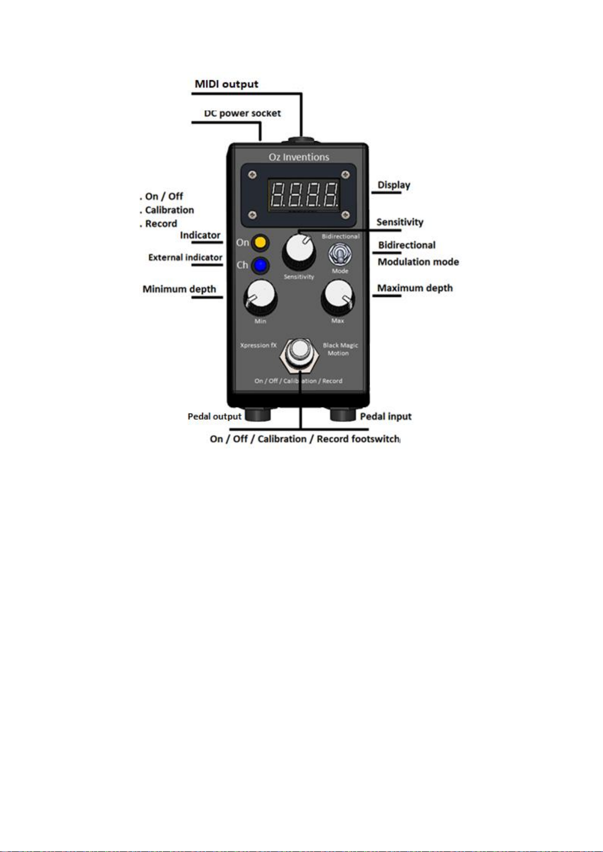
Controls and sockets overview...................................................................................................................... 10
Connecting..................................................................................................................................................... 11
Connecting the MIDI socket ...................................................................................................................... 11
Connecting the DC power adapter............................................................................................................ 12
Main indicator lights...................................................................................................................................... 12
ON.............................................................................................................................................................. 13
Ch............................................................................................................................................................... 13
Minor indicator lights .................................................................................................................................... 13
Indicator lights in normal use mode.......................................................................................................... 13
Indicator lights in menu mode .................................................................................................................. 13
Controls ......................................................................................................................................................... 14
Modulation mode switch .......................................................................................................................... 14
Bidirectional switch ................................................................................................................................... 14
Sensitivity control (0 –99)......................................................................................................................... 15
Min depth (0 –127)................................................................................................................................... 15
Max depth ................................................................................................................................................. 16
Display ........................................................................................................................................................... 17
Display in normal use mode ...................................................................................................................... 17
Indicator lights in normal use mode.......................................................................................................... 17
Display in menu mode............................................................................................................................... 17
Indicator lights in menu mode .................................................................................................................. 17
Menu ............................................................................................................................................................. 18
Menu access and control........................................................................................................................... 18
System menu items ................................................................................................................................... 20
ADSR items ................................................................................................................................................ 23
System reset .............................................................................................................................................. 26
Step size menu items................................................................................................................................. 27

4
© Oz inventions
Version 1.13
MIDI menu items....................................................................................................................................... 28
Preset selection ......................................................................................................................................... 32
Calibration ..................................................................................................................................................... 33
General calibration process....................................................................................................................... 33
Understanding recording and playback modes............................................................................................. 34
Trimming the recording............................................................................................................................. 34
Recording process ..................................................................................................................................... 35
Understanding ADSR, Automatic ADSR mode and ADSR trigger mode .................................................... 36
Default settings.............................................................................................................................................. 40
Menu item order ........................................................................................................................................... 41
Trouble shooting............................................................................................................................................ 43
MIDI implementation chart........................................................................................................................... 44
Modulator-Receiver specifications................................................................................................................ 45
Index.............................................................................................................................................................. 46

5
© Oz inventions
Version 1.13
Declaration of compliance
Manufacturers Name: Oz Inventions
Manufacturer’s address: PO Box 86, Warrnambool, Victoria. 3280
Declares that the product
Product name: Xpression fX Expression pedal enhancer (MIDI)
is compliant with the following standards regarding radiated and conductive emissions relevant to
this product and Electro Magnetic compatibility.
AS/NZS 4268
AS/NZS CISPR 32
Should the equipment cause radio frequency interference (disturber) or be the victim of radio
frequency interference, the following measures can be taken:
Relocate the disturber and/or the victim by increasing separation and/or reorientating the
device/s.
Connect the disturber and victim on different power circuits
Contact the manufacturer or other expert party

6
© Oz inventions
Version 1.13
Please read these two very important messages
1. The position of the sensitivity, minimum depth and maximum depth controls are important in
obtaining the correct amount of modulation. Having these controls in the incorrect position may
mean no modulation, little modulation or erratic modulation.
The sensitivity control is used to set the number of steps from the heel to toe position. Fully left gives
128 steps from 0 –127. Fully right gives the custom step sizes set in the ‘step size’ menu. Other positions
increase the step size. It needs to be positioned correctly, for the desired effect.
The minimum and maximum depth controls have multiple functions, operating on modulation and also
changing items and parameters within the menus, and so these controls are often moved and need to be
re-positioned for the desired effect whenever the menus are exited or the modulation mode is changed.
Failsafe starting positions outside of the menus are
Sensitivity –Fully left (0)
Minimum depth –fully left (0)
Maximum depth –fully right (127)
If at any time things are not working as expected, check those controls.
2. It is easy to assign unwanted values to the full range of continuous controllers (0 –119)
accidentally. So, when changing continuous controller numbers ensure that either the modulation
on/off switch is off, or that the continuous controller is disabled.
If the unwanted condition does occur, it may be simplest to reset the receiving MIDI device rather
than individually resetting each continuous controller.

7
© Oz inventions
Version 1.13
Provided items
Expression pedal enhancer - MIDI
DC 12 volt 150mA power supply (optional)
TRS to 5 pin DIN adapter (dependent on model and optional)
3 meter 5-pin DIN male to male (optional)
Quick start manual (optional)
Safety and care
Remove power from all devices to be connected before connecting or disconnecting
Dismantling the device may damage the device. There are no user serviceable parts inside the
device.
Only use the provided AC to DC power adapter or other certified adapter. Only use the correct
polarity of the provided reversible DC power adapter. Negative centre (tip) is the correct polarity.
The power adapter is supplied in the correct configuration. Do not reverse the connection.
Electromagnetic radiation is minimised by the aluminium enclosure and relevant internal
components. However, should interference be experienced, position the device further away from
the device that is interfering or being interfered with.
Due to the nature of modulation, some modulated parameters, particularly at the ends of
modulation, can cause a loud and/or irritating audio signal. Permanent high volume audio signals
can damage hearing and equipment.
Should the device malfunction, a reboot or restore to default settings, may resolve the problem.
Otherwise the manufacturer should be contacted. There are no user serviceable parts inside the
device.
Avoid contact with, and environments, known to cause adverse effects with electronics and small
moving parts, such as liquids, dust, sand, high humidity, high temperature and vibrations.
Avoid excessive force when operating controls and connecting cables
Disconnect the device during lightning storms and /or times of power outages
This modulating device is designed to only be connected to a MIDI receive port. Do not connect
the output socket to any other device else either device may be damaged.
If in doubt contact Oz inventions at contact@ozinventions.com

8
© Oz inventions
Version 1.13
Warranty
The device is warranted for use in Australia.
If the product is defective as a result of faulty workmanship or materials, Oz Inventions will at their
discretion repair or replace the product for a period of 12 months from purchase.
Proof of purchase is required and Oz Inventions at their discretion are required to inspect the product and
reserve the right to update or improve the product including hardware and software during the period of
inspection and /or repair.
The warranty is void if the product is opened or dismantled in any way
Warranty claims should be directed to contact@ozinventions.com
Power
The device requires a 9 –12 volt DC power supply with a current capability of 150mA. The DC polarity is
negative in the centre (tip). The supplied DC adapter is a reversible model. It is supplied with the correct
polarity configuration. Do not reverse the connection.
See Connecting the DC power adapter

9
© Oz inventions
Version 1.13
Introduction
Expression pedal enhancer - MIDI, from Oz Inventions, is a MIDI controller. It is designed for use with MIDI
devices such as keyboards and effect units with a 5-pin DIN MIDI receive socket.
The device accepts a TRS expression pedal as an input and provides unique expression capability and a MIDI
transmit output signal.
The device can function as a -
Expression pedal enhancer / MIDI controller
Triggered ADSR envelope shaper
Triggered foot switch
Recordable ADSR envelope shaper
Standalone manual ADSR envelope shaper
Foot switch / sustain switch
Automatic or triggered arpeggiator (using pitch parameter on MIDI receive device)
The device is compatible with MIDI devices that have a MIDI 5-pin DIN receive port and it has the following
features.
Controlled expression via expression pedal input and automatic and recordable waveforms
Scalable output in step sizes from 1 –127
Linear, logarithmic and anti-logarithmic sweep
Reverse, forward & continuous sweep
Adjustable minimum and maximum depth modulation positions
Adjustable start and stop sweep positions
Sensitivity control
50 millisecond to 99 second per stage, ADSR envelope shaper
triggered ADSR envelope shaper
Automatic triggered ADSR envelope shaper
15 minute motion sensing recording ADSR envelope shaper

10
© Oz inventions
Version 1.13
Controls and sockets overview
Figure 1 Top panel controls
Output jack –Tip, Ring, Sleeve type 6.35mm (¼” ) jack or 5 pin DIN (dependent on date of
manufacture)
Display –modulation mode; Sweep position; Menu text; mode indicators
Bidirectional switch –continuous output; Low to high , or high to low
Mode switch –External, Automatic, Playback
Minimum Depth –sets the minimum modulation position (heel down)
Maximum Depth - sets the maximum modulation position (toe down)
External input –connects an external device such as a TRS expression pedal
ON/OFF/calibration/record footswitch- Turns modulation on & off; Calibrates the beginning and
ending sweep points; Arms recording and stops recording.
External indicator –indicates when the ‘external’ channel is selected
ON/OFF/calibration/record indicator –Yellow
Illuminated = Modulation ON; Extinguished = Modulation OFF; Fast flashing = calibrating; Brief slow
flashing = Record armed; Continuous slow flashing = Recording in progress.
Sensitivity –sets step sizes within the sweep
DC power jack –2.1mm; 9 –12V; 150mA; Negative centre

11
© Oz inventions
Version 1.13
Connecting
The rear of the device provides access to the MIDI socket and DC power socket.
Figure 2 Rear panel connections
Connecting the MIDI socket
Connect the connect the 5-pin DIN socket to the MIDI device to be controlled using a male to male 5-pin DIN
cable.
Figure 3 –Connecting the MIDI jack
The input TRS plug/socket connection is firm and should click as it is made. The plug should be pushed gently
until it will go no further.

12
© Oz inventions
Version 1.13
Connecting the DC power adapter
Push the DC power supply plug into the DC power inlet.
Figure 4 –Push the DC power plug into the DC power inlet
The DC power plug is reversible. It is provided with the correct configuration. Should the polarity need to be
changed the arrow should point toward the negative (-) symbol. This provides the correct polarity (negative
tip) for the receiver-modulator.
Figure 5 –Correct polarity –Negative tip
Connecting multiple enhancers
Multiple enhancers can be used in series to control multiple devices with a single expression pedal. Using
each enhancers calibration function allows different parts of the pedals sweep to affect the units differently.
Figure 6 –Multiple enhancer example showing a MIDI enhancer in series with a TRS enhancer

13
© Oz inventions
Version 1.13
Main indicator lights
There are two main indicators.
ON
The ON indicator shows when modulation is on or off. When illuminated, modulation is on.
The ON indicator also indicates when calibration is occurring in ‘Free’ mode, via flashing.
The ON indicator also indicates states of recording when in ‘Rec’ mode. The indicator flashes and then goes
steady when recording is armed. The indicator starts flashing again when recording has started and stops
flashing when recording is completed.
Ch
The Ch indicator illuminates when ‘external’ is chosen as the channel of operation.
Figure 7 –Channel indicator lights
Minor indicator lights
There are two minor indicator lights and each provides unique indications in normal use mode and also
within the menus.
Indicator lights in normal use mode
In normal use mode the indicator lights signify ‘Record mode’ or ‘ADSR trigger mode’. The absence of lights
signifies ‘Free’ mode.
Indicator lights in menu mode
An illuminated dot under the last character, signifies that the menu is currently being accessed. An
illuminated dot under the first character signifies that the current menu item is an ADSR item.
Yellow
Red

14
© Oz inventions
Version 1.13
Controls
Modulation mode switch
The mode switch is a momentary toggle switch. It is toggled forward and then released. The mode switch
selects between modulation modes.
The modes are external, automatic and playback.
External (E)
This mode is designed for connecting external devices, such as a TRS expression pedal, to the TRS input
socket. Calibration may be required before use.
Automatic ADSR (A)
Plays the ADSR envelope as set within the ADSR menu
See Understanding ADSR, Automatic ADSR mode and ADSR trigger mode
Playback recorded ADSR (P)
Plays the recorded ADSR envelope as recorded in record mode. See Understanding recording pg 34
Bidirectional switch
The bidirectional switch is a permanent toggle switch. It is actuated by pushing it backward. It enables a
bidirectional sweep where the output reverses when the pedal reverses. The output will normally increase
from minimum to maximum as an external pedal is depressed and then maximum to minimum, on the way
back up again. However, with bidirectional selected, the output will reverse so that the output is minimum
to maximum in both pedal directions. (note –this is not what is called reverse sweep see pg 21 )

15
© Oz inventions
Version 1.13
Sensitivity control (0 –99)
External mode
The sensitivity control adjusts the step size within the sweep. Fully left (1) gives individual steps of 1, from 0
–127. Next right (2) gives individual steps in 2’s (e.g 0, 2, 4, 6…. Etc). Turning right continues the step size
increase. Fully right (128) assigns the device to use the custom step sizes set in the step size menu (see step
size menu pg 27 .
Playback mode
The sensitivity control is used as a trim control in playback mode to remove possible uneven timing toward
the end of the recording. See ‘Understanding recording’ pg 34
It is important to have the sensitivity control in the correct position for each mode. If it is in the wrong
position, the result can be no or erratic output. If at any time the output is not working as expected, check
the sensitivity control, and also the min and max depth controls.
Min depth (0 –127)
The minimum depth control limits the output by preventing it falling below a preset level. For example,
when minimum depth is set to 25, output cannot go lower than 25. For example, if the chosen parameter to
be modulated is ‘volume’ with a range from no volume at 0, to maximum volume at 127, setting the
minimum depth control to 25 will prevent the volume from reaching zero. In relation to a traditional
expression pedal, the minimum depth control can be likened to how far down the heel is pressed.
Knowing the exact position of the minimum depth control is not always needed, however its level is briefly
flashed on the screen whenever it is moved. Fully left = 0. Fully right = 127.
The minimum depth control also functions as the menu item indexer. The control does not function as a
depth control when a menu is accessed. However, its depth value is retained by the system when inside a
menu. When a menu is exited the control should be returned to the position it was in before menu entry.
It is important to have the minimum depth control in the correct position for the result you are trying to
obtain. If it is in the wrong position, the result can be no output. Whenever the menu is exited, be sure to
correctly place the minimum depth control. If at any time modulation is not working as expected, check
the minimum depth control, and also the maximum depth control and the sensitivity control.

16
© Oz inventions
Version 1.13
Max depth
The maximum depth control limits the output from rising above a preset level. For example, when maximum
depth is set to 90, the output cannot go higher than 90. For example, if the chosen parameter to be
modulated is ‘volume’ with a range from no volume at 0, to maximum volume at 127, setting the maximum
depth control to 90 will prevent ‘maximum volume’ being reached. In relation to a traditional expression
pedal, the maximum depth control can be likened to the toe down position.
Knowing the exact position of the maximum depth control is not always needed, however its level is briefly
flashed on the screen whenever it is moved. Fully anti-clockwise is 0, fully clockwise is 127.
The maximum depth control also functions as the menu item parameter indexer. The control does not
function as a depth control when a menu is accessed. However, its depth value is retained by the system
whilst in the menu. When the menu is exited the control should be returned to the position it was in before
menu entry.
It is important to have the maximum depth control in the correct position for the result you are trying to
obtain. If it is in the wrong position, the result can be no changing output. Whenever a menu is exited, be
sure to correctly place the maximum depth control. If at any time modulation is not working as expected,
check the maximum depth control, and also the minimum depth control and the sensitivity control.

17
© Oz inventions
Version 1.13
Display
In normal use mode, the display shows the sweep position and the current mode. The display also shows
menu information and has indicator lights to signify a menu is currently being accessed, and also indicator
lights outside of a menu to show when ADSR trigger, and Record mode are selected.
Display in normal use mode
In normal use mode, the display shows the currently chosen mode and the modulation output level of that
mode.
Indicator lights in normal use mode
In normal use mode the indicator lights signify record mode or ADSR trigger mode. The absence of lights
signifies ‘Free’ mode.
Display in menu mode
In Menu mode, the display shows the currently selected menu item and its current parameter level. An
illuminated dot under the last character distinguishes between menu access and normal use mode.
Indicator lights in menu mode
An illuminated dot under the last character, signifies that the menu is currently being accessed. An additional
illuminated dot under the first character signifies that the current menu item is an ADSR item.

18
© Oz inventions
Version 1.13
Menu
There are three menus and a preset select option.
1. The system menu holds system items and ADSR items–
System items –record trigger level, reverse sweep direction, record time, linear/log sweep, and
selects Free mode, ADSR trigger mode 1, ADSR trigger mode 2 & Record mode.
ADSR items –holds ADSR settings: - attack rate, decay rate, sustain level, sustain time, release
rate and trigger modes.
2. The step size menu holds step size items. Variable step sizes from 1 –127 and custom step sizes
3. The MIDI menu holds MIDI items: - MIDI channel, program change, Continuous controllers, MIDI
reset functions
4. There are 10 available presets. Unless changed, each preset holds the same default information.
There is also a reset option accessed during power on that returns the unit to default settings See pg 23
Menu access and control
Figure 8 –Menu Access and control
The system menu is accessed by first pressing and holding the on / off / calibration /
record switch and then pulling forward the modulation mode toggle switch. Both
switches must be held together, with the on/off/calibration/recording switch being
held first.
The ‘Step size’ menu is accessed by first pulling forward and holding the modulation
mode toggle switch and then pressing the on/off/calibration/recording switch. Both
switches must be held together, with the toggle switch being held first.
Once inside a menu the minimum depth control moves through the menu items and
the maximum depth control changes the parameters of the currently selected menu
item. Exiting the menu is done in the same way as entry.
The ‘MIDI’ menu is accessed by first rotating the maximum depth control fully anti-clockwise and
then pressing and holding the on/off/calibration/record switch and then pulling forward the
modulation mode toggle switch. Both switches must be held together, with the
on/off/calibration/recording switch being held first. The MIDI menu is exited by pressing the
on/off/calibrate switch whilst pulling the modulation mode switch.

19
© Oz inventions
Version 1.13
The presets are access by rotating the maximum depth control fully anti-clockwise (0) and rotating
the minimum depth control fully clockwise (127) and then pressing the on/off/calibration/recording
switch. The presets can then be changed by pulling forward the modulation mode toggle switch. To
exit preset selection, change the minimum or maximum depth control to any position.
‘SyS’ appears on the display briefly when the system menu is entered. The display then shows the
first menu item
‘Stp’ appears on the display briefly when the ‘Step size’ menu is entered. The display then shows the
first menu item.
‘nidi’ appears on the display briefly when the MIDI menu is entered. The display then shows the first
menu item.
‘PS’ appears on the display when ‘Preset’ selection is entered. ‘
A small illuminated dot is permanently on under the last character on the display to signify that a
menu has been entered.
A small illuminated dot is also permanently on under the first character of the ADSR settings only, to
distinguish between the ADSR settings and the other settings.
Exit from a menu is done in the same way as entry.
The individual items of a menu are indexed via the minimum depth control.
The individual menu item parameters are modified by the maximum depth control.
After meu exit, it is important to that these controls be returned to the position they were in before
entry, depending on what is required.
Calibration is not possible when in ADSR or Record mode. Any calibration should be carried out
before entering these modes.
The output ON/OFF switch functions as normal when in the menus
The minimum and maximum depth controls do not function as depth controls when in the menu.
However, their depth values at the time of menu entry are retained whilst in the menu.
After menu exit the min and max depth controls will take on the values relevant to their current
position and so,
After menu exit, It is important to return the depth controls to their required positions
System reset
System reset is actuated by holding the modulation mode switch forward, whilst applying power, and then
releasing the switch. The system is then returned to default settings. See pg 40

20
© Oz inventions
Version 1.13
System menu items
The system items in the menu enable adjustment of system settings
Free/ADSR trigger mode 1 / ADSR trigger mode 2 / Record
Default –Free; Range - Free, Atr1, Atr2 & Record
Free
Output is based directly on the changing mode data (external, automatic or playback). The range is 0 –127
and can be modified via the minimum and maximum depth controls. For example, with the minimum depth
control set at minimum and the maximum depth control set at maximum, the output will range from 0 –
127. Reducing the maximum control will reduce the modulating output from 127. Increasing the minimum
control will increase the beginning modulation above 0.
Atr1 (ADSR trigger mode 1)
The ADSR envelope will be triggered on and off by the modulating output, as per the ADSR trigger settings in
the menu. The external pedal will have no affect on the output as it passes through its sweep, other than at
the trigger point of the maximum depth setting, where it will turn ADSR on or off.
Atr2 (ADSR trigger mode 2)
The ADSR envelope will be triggered on and off by the output, as per the ADSR trigger settings in the menu.
The external pedal will continue to affect the output as it passes through its sweep, and also trigger the
ADSR on and off at the trigger point. The trigger point is the maximum depth level.
Rec (Record)
The device will record the input for a duration between 0 to 1000 seconds dependent on the ‘Recording
Time’ set in the menu. The recording can be heard by selecting playblack (‘P’) with the modulation mode
switch. The recording will play back continuously and can be trimmed using the trim (sensitivity) control. The
recorded waveform cannot be saved.See Understanding recording pg 34
Other manuals for Xpression fX
3
Table of contents
Other Oz inventions Music Pedal manuals