Ozone Solutions Waterzone Series User manual

WATERZONE SERIES
OZONE INJECTION SYSTEM
MODEL: WZ-100, 150, 200
INSTALLATION & OPERATIONS MANUAL
451 Black Forest Road /Hull, Iowa 51239 USA
P 712.439.6880 /F 712.439.6733


WZ SERIES /3
INSTALLATION & OPERATIONS MANUAL
IMPORTANT SAFETY INSTRUCTIONS, READ AND FOLLOW ALL INSTRUCTIONS.
Read this manual completely before attempting installation.
SAVE THESE INSTRUCTIONS.
CONTENTS
SECTION 1
Safety Precautions .........................................................4
Introduction ....................................................................4
Theory of Operation .......................................................4
SECTION 2
Component Diagram......................................................6
Components Description ...............................................6
Specications .................................................................7
Installation......................................................................8
Location and Mounting..................................................8
Mechanical Connections ...............................................8
Electrical Power Connections........................................9
Optional Electrical Connections ....................................9
SECTION 3
System Operation...........................................................9
Ozone System Initial Startup Procedure.....................10
SECTION 4
HMI Control Display - Overview ...................................11
SECTION 5
Personal Safety ............................................................13
Warranty .......................................................................14
Contact Information .....................................................14
APPENDIX A - CAD DRAWING..............................15
APPENDIX B - MAINTENANCE..............................16
APPENDIX C - TROUBLESHOOTING ..................... 17
APPENDIX D - SAFETY DATA SHEET....................18

4/WZ SERIES
OZONE SOLUTIONS
SECTION 1
SAFETY PRECAUTIONS
Ozone is a powerful oxidizing agent. Observe strict
operating procedures while using ozone equipment.
It is imperative that only ozone compatible materials
are used in conjunction with the ozone system.
Ensure that the Ozone Generator is in a well-ventilated
area. Do not allow rain or condensation to contact the
Ozone Generator. The Ozone Generator is not weather
proof. The unit must be operated indoors or in an
enclosure in a non-condensing environment.
Carefully review and familiarize yourself with the
following important safety information concerning the
Ozone Generator:
1. Ozone is an extremely aggressive and powerful
oxidizer. The Occupational Safety and Health
Administration (OSHA) 8-hour exposure limit is
0.10 PPM. The OSHA 15 minute exposure limit for
ozone is 0.3 PPM. Above 0.3 PPM, there is the risk
of damage to respiratory tissues.
2. People who have no sense of smell should not
operate this equipment.
3. Never attempt to verify ozone production by directly
breathing or smelling the ozone outlet.
4. The Ozone Generator contains high voltages.
Unauthorized entry can result in serious injury or
death. For service instructions, contact Ozone
Solutions.
5. Make sure all tubing connections between the
Ozone Generator and the injection point are secure
and in good working condition. Failure to do so
could result in the discharge of ozone into an
undesired space.
INTRODUCTION
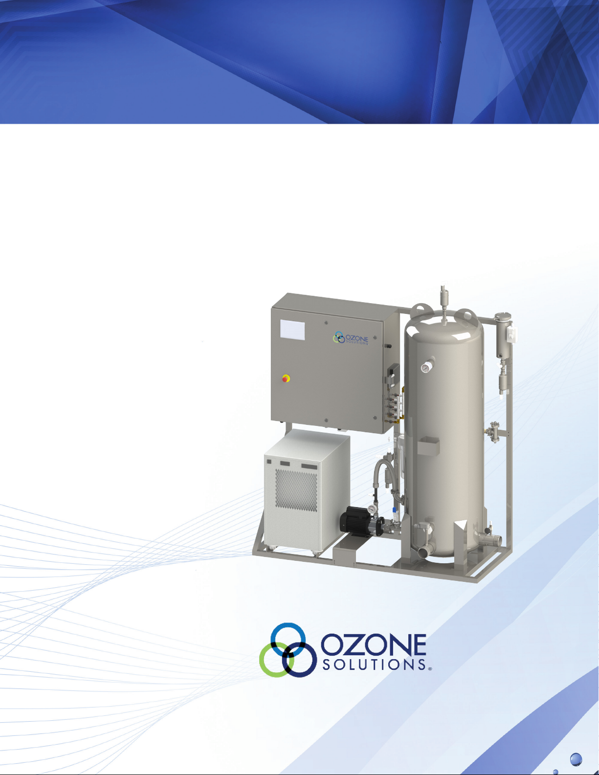
The Waterzone series ozone systems are a complete
oxygen preparation, ozone generation, and injection
system that include the integrated oxygen sieves, ozone
generator, pump, injector, and contact Tank. External
compressed air may be required.
This skid has a control system to control all functions
of the ozone generator and ozone injection system
automatically. Each of these functions will be described
in this manual. Please read and familiarize yourself
with this and other related operation manuals before
use.
THEORY OF OPERATION
The purpose of this system is to use ozone as a
disinfectant for water. Ozone is a very reactive gas
that must be produced on site. Ozone in the gaseous
form is also very unstable and difcult to manage in
an effective way for any reliable disinfection processes.
Because of these factors, the ozone is dissolved into
water whereby it can be applied effectively to the
surface of any food product or other item that may
require disinfection.
The ozone is produced using ozone generator cells. The
ozone generator produces 100-200 g/hr (depending
on model) of ozone from oxygen feed gas. This oxygen
feed gas is concentrated from compressed air supplied
by the internal oil-free air compressor, if equipped,
or the provided plant air. The oxygen concentrators
use pressure swing adsorption (PSA) technology
with a zeolite material to purge the nitrogen from the
compressed air leaving 90-95% oxygen feed gas for the
ozone generator. This oxygen is passed through ozone
generator cells which uses a controlled high voltage,
high frequency spark, called a corona, to convert as
much oxygen (O2) into ozone (O3) as possible. The result
is 5-8% ozone in an oxygen stream of 32-64 SCFH
leaving the Ozone Generator at pressures up to 14 PSI.
The process of converting oxygen into ozone is an
energy intensive process that generates a large amount
of heat. This heat must be removed from the ozone
generating cell for efcient and reliable operation. The
ozone generator in this system uses water cooled cells
and a water chiller to remove this heat. The water chiller
has an onboard pump to operate the cooling circuit.
This ozone/oxygen mix is dissolved into the water using
the Ozone injection system. To efciently dissolve this
ozone into the water, a Venturi Injector is used to pull
the ozone into the water. The water pump is used
to increase water pressure prior to the venturi. The
pressure at the outlet of the venturi must be at least
20 PSI lower than the inlet pressure. This pressure
differential creates a vacuum that will pull the ozone
NOTE: If the operator has asthma, he or she must
not enter an airspace that has a signicant ozone
concentration. Ozone can induce an asthma attack.

WZ SERIES /5
INSTALLATION & OPERATIONS MANUAL
into the venturi. This forceful action along with the
added mixing vanes in the venturi injector provides for
an extremely efcient method of dissolving the ozone
gas into water.
Naturally, the excess oxygen and a small amount of
undissolved ozone must be removed from the water;
this occurs in the contact tank located on the skid.
Bafes inside this skid ensure that no oxygen/ozone
gas will escape with the water. All of the undissolved
oxygen/ozone is removed through the vent on the top
of the contact tank so that it can be safely destroyed or
removed from the location.
The water passing through the ozone injection system is
unimpeded and will ow at the desired rate at the point
of use. Water with dissolved ozone levels necessary
for proper disinfection can be used for any purpose
desired.
AIR
IN
O2
OUT
OPTIONAL AIR
COMPRESSOR
Untreated Water
Untreated Water +
Ozone
Venturi Injector
Dissolved Ozone
Monitor
To Drain
Undissolved Ozone
Gas
Heated Ozone
Destruct Unit
Water Chiller
OZONE GENERATOR
(Water Cooled)
Oxygen Concentrator
Air Intake
Filter
Injection Pump
Treated Water +
Ozone Out
Untreated Water In
Cooling Water Lines
Ozone
Gas
To Atmosphere
Items shown in dashed line are
assembled onto one skid
Water
Contact
Tank

6/WZ SERIES
OZONE SOLUTIONS
SECTION 2
COMPONENT DIAGRAM
1
6
8
9
10
7
5
4
3
2
16
8
18
14
13
12
11
17
15
19
COMPONENTS DESCRIPTION
1. Ozone Destruct Unit: Safely converts off-gassed
ozone into oxygen using a catalyst material. The
destruct unit uses a heater band to keep the
catalyst bed warm. This is to ensure no moisture
condensates on the catalyst. As long as the
Waterzone is connected to electrical power, this
canister should be warm (sometimes hot) to the
touch.
2. Emergency Stop Push Button: Allows you to easily
turn the system off quickly by pushing this switch.
3. HMI: This touch screen allows workers to control the
machine and view alarm conditions
4. Air Vent: Safely removes all off-gassed ozone/
oxygen from the system. The gas ow from this vent
must be vented to a safe outdoor location or into an
ozone destruct unit.
5. Ozone Injection Pump: This pump creates the
pressure differential necessary across the venturi
injector for ozone injection. This pump should be
operating any time the Green Pump light on the
control panel is ON.
6. Injection Inlet Pressure Gauge: Indicates water
pressure on the inlet side of the venturi injector.
This pressure should be at least 20 PSI higher
than the injector outlet pressure gauge. Any time
the ozone injection pump is running this pressure
gauge should be higher than the injector outlet
pressure gauge.
24
23
22
21
20

WZ SERIES /7
INSTALLATION & OPERATIONS MANUAL
7. Venturi Injector: A Venturi Injector is used to pull the
ozone into the water using a vacuum and mix this
ozone gas into water very efciently. For the venturi
action to occur, a minimum pressure differential
of approximately 20 PSI must be maintained.
The differential is determined by guring the
difference between the pressures indicated at the
inlet and outlet of the Venturi Injector. The outlet
pressure is equal to Contact Tank pressure, and
basically indicates the pressure exerted on the
Ozone injection system by the outside source.
The inlet pressure will increase or decrease along
with this pressure, but a constant differential will
be maintained as long as the Injector Pump is
operating properly.
8. Water Trap: These units prevent water from owing
with the gas stream to the ozone destruct unit, and
potentially the ozone generator (in a reverse ow
situation). Any water that may ow with these gas
streams will be trapped in the bowl of the water trap
and safely drained out via tubing to a oor drain.
9. Tank Pressure Gauge: Indicates water pressure on
the outlet side of the Venturi Injector. This pressure
will be equal to the contact tank pressure and
basically indicates the pressure exerted on the
ozone injection system by an outside source. This
pressure should be at least 20 PSI lower than the
injector inlet pressure gauge.
10. Contact Tank: This tank mixes the ozone gas with
the water to be treated. Using bafes and specic
inlet/outlet design, maximum mass transfer
efciency of the gas to water is achieved. While
most ozone is dissolved into the water, some
ozone/oxygen will off-gas through the vent in the
top of this contact tank.
11. Water Inlet: Connection for incoming water.
12. Flow Switch: The Flow Switch recognizes there is
water owing through the tank and tells the controls
in the system.
13. Water Outlet: Connection for efuent water.
14. Cooling Water Flow Meter: Indicates water ow
rate through the cooling water loop of the ozone
generator. This ow can be regulated with the
integrated ow control knob on the ow meter. Flow
should be 30-40 GPH.
15. High Pressure Check Valve: This check valve is to
make sure that water does not ow back up the
ozone line.
16. Low Pressure Check Valve: This check valve is a
secondary to the high pressure check valve
17. Dissolved Ozone Monitor: Flow cell with remote
mounted sensor probe.
18. Flow Cell Needle Valve: This valve regulates the
ow of ozonated water across the dissolved ozone
monitor probe
19. Water Chiller: This unit chills the cooling water
through the ozone cells.
20. Ethernet Port: This port allows connection to the
PLC system
21. Oxygen Flow Meter: Indicates the ow of oxygen
through the Ozone Generator.
22. Ozone Flow Regulating Valve: Turn this knob to
regulate oxygen ow through the Ozone Generator,
Flow is indicated through the oxygen ow meter
adjacent to the valve.
23. Compressed Air Inlet
24. Cooling Water Filter: This lter protects the water
chiller from particulate.
SPECIFICATIONS
Waterzone Ozone Production
(g/hr.)
Oxygen Flow
Rate (SCFH)
Dimensions HxWxD (in) Max Flow Rate
(GPM)
Voltage (Volts)
Waterzone-100 100 32 83x78x34 200 220 4-wire
Single phase
Waterzone-150 150 50 89x78x33 300 220 4-wire
Single-phase
Waterzone-200 200 64 89x78x33 300 220 4-wire
Single-phase

8/WZ SERIES
OZONE SOLUTIONS
INSTALLATION
IMPORTANT: Keep in mind that the intake of the
pump(s) must be ooded with water (water level
above pump head) every time the pumps are started
or running, as they are not self-priming. Operating the
pumps dry will cause pump damage. Be sure to have
the pump head ooded with water anytime the pumps
are started or running.
IMPORTANT: Proper oor drainage is required to
prevent water damage in case of water leak or overow.
Ventilation: The system should be installed in a well
ventilated area, in accordance with the environmental
specications outlined in the individual Operation
Manuals associated with this system.
LOCATION AND MOUNTING
The ozone injection system should be installed in such
a way that all components of the system are accessible
for future maintenance. Working area required around
the system must be made available on three sides. A
minimum of 30 inches should be left for working area
around the front and both sides. The rear of the system
can be mounted against a wall or another object.
The ozone injection system is not rain or drip proof, and
therefore should be protected from rain and splashing
water. Filtered cooling inlets provide a level of protection
against dust; however for maximum longevity the
system should be located in a clean, dry area.
If the system is to be mounted in a mobile unit (such
as a trailer or movable building), mechanical shock
and vibration prevention measures need to be taken
to protect the system from damage during relocation of
the mobile unit.
Ensure that the location chosen ensures a maximum
temperature of 95°F and a maximum relative humidity
of 85%. If the parameters above cannot be maintained,
cooling and/or dehumidication equipment must be
installed. There may be exceptions to the environmental
guidelines for certain system congurations, contact
Ozone Solutions if the environmental conditions are
not as prescribed above, or otherwise in question.
MECHANICAL CONNECTIONS
Connect water piping at the ttings provided at the
edge of the skid. Ball valves at the inlet and outlet of
the system are required to allow isolation, congured
in such a way that the system can be isolated and/or
bypassed for maintenance purposes.
Process Water In
Water is supplied to the tank tting near the front-center
of the system. The water ow switch is also installed in
this tee.
Process Water Out
Ozonated water exits the tank tting on the right side
of the tank. If different plumbing connections are
required, adapters can be provided.
Water Sample Port
Ozone residual in the water must be checked
periodically to ensure proper operation of the ozone
injection system. This is also used to calibrate the
dissolved ozone sensor (if applicable). After the output
of the Ozone injection system, a small tee with a ball
valve should be placed in the water line. This will allow
for samples of water to be pulled to verify the dissolved
ozone level in the water.
Dissolved Ozone Monitor
Measures the dissolved ozone level exiting the contact
tank. The black cap needs to be pulled off of the tip
for it to work. Read and understand the provided
sensor instructions. The manual will inform you of the
maintenance and calibration of this probe.
Ambient Ozone Monitor
This type of monitor is to display an ozone reading
measured from the ambient air. The most common
monitor chosen is the F12 unit. This monitor can be
installed remotely from the Waterzone unit to ensure
safe conditions for employees working in the same room
as the unit, or near the ozone point of use. The output
of the monitor can be tied into the PLC system of the
Waterzone to allow automatic shut down procedures.

WZ SERIES /9
INSTALLATION & OPERATIONS MANUAL
Air Vent
The air vent is located on the top of the Contact Tank.
The 1/2 inch port exiting the air vent will need to be
plumbed outdoors away from human contact or to a
suitable ozone destruct unit, as it will be off-gassing
small amounts of high-concentration ozone. Ozone-
compatible tubing and ttings should be used for this
purpose.
Waterzone systems are congured with an Ozone
Destruct Unit installed on the skid. The gas exiting
this ozone destruct unit should still be plumbed to a
safe location in the event the destruct unit fails for any
reason. It is important that this gas is removed from
human contact and vented to a safe location.
Water Trap Drain
The Water Trap is located on the Ozone Injection Skid.
This water trap will drain any water that may be pushed
from the Venturi Injector toward the Ozone Generator;
this is a protection device for the Ozone Generator.
There may also be a water trap installed to drain any
water from the off-gas vent outlet prior to the ozone
destruct unit.
These water traps may collect a small amount of water
that will need to be plumbed away to a drain. Any drain
tubing must be run DOWNHILL in order to freely drain.
Use tubing with an ID of no less than 3/8 inch, with a
maximum of 5 feet.
ELECTRICAL POWER CONNECTIONS
The system requires a 220 Volt, 4 wire, 30 Amp, 60 Hz
single phase circuit. The unit is installed with a NEMA
cord end for easy power up.
OPTIONAL ELECTRICAL CONNECTIONS
CAUTION: Voltage may be present at connection
terminals! Disconnect all power before servicing.
Terminals are provided for connection of external
contacts to control and monitor the system. The
terminals are located inside the System Controller.
Drill holes in the System Controller as necessary for
connection of external control wiring.
These connections may be used optionally as desired.
Some terminals are jumpered from the factory to allow
the system to operate without external connections.
On terminals which are jumpered, the jumper must
be removed upon connection of remote contacts. If
control wires are used in the terminals currently, these
can be run in series with any remote control device of
your choice to power the system remotely.
SECTION 3
SYSTEM OPERATION
IMPORTANT: Read and understand the “Personal
Safety” section of this manual before operating the
Ozone System.
Water Flow
Water ow through this ozone injection system will
be dependent upon the supply water connection to
maintain pressure on the system. The ozone injection
will occur regardless of the rate of ow through the
contact tank, as long as the tank remains full of water.
Higher water usage will result in lower dissolved ozone
levels, while lower water usage will result in higher
dissolved ozone levels. This is due only to the ratio
of ozone to water. Keep this in mind when specic
dissolved ozone levels are required for your operation.
Water Pressure
This ozone injection system will not operate effectively
with water pressures exceeding 50 PSI. If water
pressures are higher, then water pressure should be
regulated ahead of the ozone system so that it can be
adjusted to maintain lower pressures.
If the water will be used for spraying or washing
purposes, the water pressure should be kept below
30 PSI. This is to ensure that the ozone will remain

10 /WZ SERIES
OZONE SOLUTIONS
dissolved into the water. Higher spray pressures will
off-gas a large amount of the dissolved ozone from the
water in the spraying process. This is not a desirable
situation for the disinfection process, or for human
safety.
Injector Pump
The Injector Pump is a dedicated pump to mix the ozone
with the water. This pump will create the necessary
pressure differential across the Venturi Injector to
create the necessary vacuum to draw ozone into the
water stream. This pump will also mix the ozone with
the water in the contact tank by recirculating this
water through the injector at a ow rate necessary for
injection. This pump will start and stop automatically.
Water Chiller
The water chiller is a standalone chiller with a sole
purpose of cooling the ozone cells. Be sure that the
chiller’s main power switch is ON whenever the main
system is on. Failure to do so will result in overheating
of the cells, which will cause poor ozone production
and will damage the cells.
System Control
Read the “Ozone System Controls and Indicators” to
become familiar with the individual components before
attempting to operate the system. The system can be
operated from a remote location if the optional external
control connections are used. For more information
see the “Installation: Optional Electrical Connections:
section in this manual.
Local Operation
For normal day-to-day operation, the initial startup
procedure may be followed. The system can be started
by pressing the START button on the screen; all other
controls will automatically start as necessary.
Remote Operation
There are external connection terminals located
inside the system controller that can START or STOP
the system from a remote location. The external push
buttons can START or STOP the system by momentarily
closing the contacts. This may be convenient when
there is another control system that will be starting
other equipment associated with the ozone system.
OZONE SYSTEM INITIAL STARTUP
PROCEDURE
IMPORTANT: Read and understand the “Caution,
Warnings and Hazards” section of this manual before
operating the ozone system!
1. As a safety measure, ensure that the Variable
Ozone Output is set to “0” during initial setup and
rst starting of the system (so that ozone is not
produced).
2. Remove the black protective cap from Dissolved
Ozone Monitor probe before lling with water.
3. Open the water valves on the piping system to allow
water ow into the system and ll the Contact Tank.
The Contact Tank is full when the tank pressure
gauge reads equal to the supply water pressure.
This system check also ensures that the pumps
are primed with water. IMPORTANT: Do not start
the system unless it is full of water, as equipment
damage may result in the event of a dry start.
4. Inspect all water connections for leaks.
5. Allow water to ow through the system by opening a
valve upstream of the system.
6. Connect clean, dry, compressed air to air-in
bulkhead on enclosure, if not equipped with
internal compressor option.
7. Start the ozone injection system by pressing the
Start button on the screen. When set to AUTO,
the injection pump and oxygen concentrator will
start. Verify that the pump outlet pressure rises to
indicate the pump is working.
8. Ensure that the Ozone Generator oxygen ow does
not exceed the limits outlined in the manual. Setting
the ow to about 8-10 LPM is a safe starting point
for this ow, and can be slowly increased once the
system stability is veried. This ow is adjusted
manually using the ow control valve near the
owmeter, and may be affected by varying water
pressures. Normally if adequate water pressure is
applied to the contact tank the oxygen ow will not
exceed its limits.
9. Ensure that air bubbles are escaping from the air
vent; this will indicate the oxygen is being introduced
into the water and off-gassed effectively. Normally,
a small amount of water will periodically exit the air

WZ SERIES /11
INSTALLATION & OPERATIONS MANUAL
vent along with the air. If adequate off-gassing does
not occur, the tank will eventually ll with oxygen/
ozone gas and cause injection pump cavitation and
result in low dissolved ozone levels. It may take a
matter of minutes or hours for such a problem to
become obvious.
10. The Variable Ozone Output may be turned up at this
time to begin producing ozone. IMPORTANT: Verify
that the water chiller is turned on and operating
before producing ozone.
11. The Dissolved Ozone Level on the Dissolved Ozone
Monitor should being to rise within ve (5) minutes
of startup. NOTE: The dissolved ozone sensor will
require time to stabilize in the process before full
accuracy is reached. Normally this occurs within a
few hours, but may require more time. See AS-500,
AV88, Q45H, or Q46H Dissolved Ozone Monitor
and Sensor operation manuals for details.
12. Depending on the application, the Dissolved Ozone
Monitor settings may need to be adjusted for the
HIGH and LOW alarms. See the System Operation
section of this manual.
13. To stop the system simply press the STOP button
on the screen. The system will automatically enter
a ush cycle then shut down.
SECTION 4
HMI CONTROL DISPLAY - OVERVIEW
Displays measured compressed
air pressure
Brings up Component Control
Screen for inlet ball valve
Brings up Component Control
Screen for oxygen concentrators
Displays ozone inverter output
level setting, changeable in the
Set Point Screen
Brings up Component Control
Screen for ozone inverters
Displays current system status
and automated process step
Displays Hour Meter
of system running
Brings up the Alarm
Screen
Brings up the Trend
Screen
Brings up the Set
Point Screen
Brings up Component
Control Screen for the
injection pump
Displays measured
dissolved ozone level at
tank outflow
Displays measured remote
ozone level in ambient air
Displays measured
compressed oxygen
pressure
Displays measured
compressed ozone
pressure

12 /WZ SERIES
OZONE SOLUTIONS
Displays active and
acknowledged alarms.
Acknowledges all alarms
displayed
Controls upper and lower conditions
for air pressure. System will start
when inlet air pressure exceeds
Start Up Set Point, and shut down
when below Shut Down Set Point.
Controls upper and lower conditions
for oxygen pressure. System will
start when oxygen pressure exceeds
Start Up Set Point, and shut down
when below Shut Down Set Point.
Controls upper and lower conditions
for ozone pressure. System will
start when ozone pressure exceeds
Start Up Set Point, and shut down
when below Shut Down Set Point.
Controls the length of time that the
system runs, with inverters off,
during shut down operation.
Controls the length of time that the
system runs, with inverters off, when a
leak is detected.
Controls the maximum measurement
level acceptable in ambient
conditions. If measured levels exceed
this point, the system enters a leak
flushing cycle.
Controls upper and lower conditions
for dissolved ozone. System will start
when dissolved ozone is below ON set
point, and shut down when below OFF
Set Point.
Allows the system to automatically
control output based on readings
from the dissolved ozone monitor.
Allows the system to automatically
control flow through the system.
Important: Changing set points requires the user to be logged in as supervisor

WZ SERIES /13
INSTALLATION & OPERATIONS MANUAL
SECTION 5
PERSONAL SAFETY
Flushing ozone from the system
Safety warnings regarding ozone gas are found at the
beginning of this manual. The Ozone System produces
a large amount of ozone, which can be inadvertently
“stored” within the Ozone Generators, manifolds, and
ozone lines.
NOTE: In most circumstances, a very small amount
of ozone will be contained within the system after
shutdown and therefore exposure will be minimal.
Eventually the ozone (even while in the system) will
safely revert back to oxygen, but in the right conditions
the ozone can remain in the system for 24 hours or
even longer. In the event that maintenance must
be performed on the components in contact with
ozone, the following is recommended for reducing the
possibility of exposure to the ozone.
Whenever possible it is recommended that the machine
run with maximum permissible air and oxygen ow for
at least 10 minutes with the Ozone Generator OFF in
order to ush out most residual ozone.
If the machine cannot be operated prior to maintenance
or repair, a waiting period of 12 to 24 hours (if ozone
has been produced recently) is recommended to allow
the ozone to decay by reverting back into oxygen.
Isolating energy sources
The Ozone Generator has electrical and mechanical
hazards, and maintenance or repair should not take
place unless all energy sources have been turned off,
disconnected, and/or drained. Energy sources include,
but are not limited to:
• Electrical power
• Oxygen Concentrator sieve beds
• Ozone Generator internal capacitors
WARRANTY
Ozone Solutions warrants all new equipment
assembled, manufactured, and sold to be free from
defects in material and workmanship under normal
use and service for a period of one (1) year after date
of sale to the original purchaser.
Displays a graphical trend of
several data points.

14 /WZ SERIES
OZONE SOLUTIONS
Some products may have a specic warranty period
other than what is outlined in this document. For such
products, the manufacturer warranty will supersede
this warranty. Ozone Solutions will honor the
manufacturer’s warranty, but if and when advised by
the manufacturer, may have the customer deal directly
with the manufacturer.
This warranty covers all parts that are not outlined in
a product maintenance schedule. This warranty will be
void if any piece of the equipment is used in a manner
other than what is explicitly outlined in the product
manuals.
If any part of the equipment manufactured by
Ozone Solutions proves to be defective during the
warranty period, please contact Ozone Solutions at
Prior authorization is required before working on
or shipping a product back to us. Failure to get prior
authorization may result in denial of your claim. Once
authorized, you may return the defective equipment
to Ozone Solutions with the transportation charges
prepaid. If Ozone Solutions nds the equipment to
be defective, it will be repaired or replaced at our
discretion, free of charge, to the original purchaser
(F.O.B. factory).
This warranty shall not place any liability on Ozone
Solutions for any transportation charges, labor, or
cost for, or during the replacement of any parts.
The replaced part (s) or product will then continue
the original warranty duration. The replaced parts
will not start a new one (1) year coverage period.
The purchaser by acceptance of the equipment will
assume all liability for the consequences of its use or
misuse by the purchaser, employees, or others. This
warranty shall not apply to any piece of equipment,
or part thereof sold by this company which has been
subject to any accident caused in transit, alterations by
unauthorized service, negligence, abuse, or damage by
ood, re, or act of God.
This warranty shall constitute the entire warranty and/
or agreement between Ozone Solutions and the original
purchaser, and in lieu of all other warranties, expressed
or implied, either oral or written, including the warranty
of merchantability and tness for a particular use and
of all other obligations or liabilities on our part. Ozone
Solutions neither assumes nor authorizes any other
person or entity to assume for us any liability associated
with the sale of its products or equipment.
The term “original purchaser,” as used in this
warranty, means whom the product was originally
sold to by Ozone Solutions or by an authorized dealer.
Ozone Solutions reserves the right to make changes
in its products without notice. Because of this, Ozone
Solutions is not obligated to replace warranty defective
part (s) and/or product with the same original part or
product.
CONTACT INFORMATION
Ozone Solutions, Inc.
451 Black Forest Road
Hull, IA 51239 USA
Phone: 712.439.6880
Fax: 712.439.6733
Email: [email protected]
Website: www.ozonesolutions.com

WZ SERIES /15
APPENDIX A - CAD DRAWING
77.7
89.0
33.0
THE INFORMATION CONTAINED IN THIS
DRAWING IS THE SOLE PROPERTY OF
OZONE SOLUTIONS. ANY REPRODUCTION
IN PART OR AS A WHOLE WITHOUT THE
WRITTEN PERMISSION OF OZONE
SOLUTIONS IS PROHIBITED.
PROPRIETARY AND CONFIDENTIAL
ENG APPR.
DATE
NAME
TITLE
TB
2/5/2019
WZ-150
A A
B B
2
2
1
1

16 /WZ SERIES
APPENDIX B - MAINTENANCE
All major components requiring maintenance have guidelines listed in the respective operation manuals. Refer
to those individual operation manuals for other preventative maintenance and regular maintenance information.
Maintenance Table
COMPONENT ACTION TIME INTERVAL PART NUMBER(S)
Compressed Air Filter Replace the lter element 3 months/as needed PR-8: Replacement lter
Compressed Air Filter Replace the lter element 3 months/as needed CF-8: Repl. Filter
Water Chiller Filter Replace the lter element 3 months/as needed Ecopure EPW2C Filters
Dissolved Ozone Sensor Replace the Electrolyte 6 months, dependant
on water quality
AS-500 Electrolyte
Dissolved Ozone Sensor Replace the at cap 1 year AS– Membrane Cap Flat
Ozone Leak Sensor Replace the sensor 1 year OEM-3: RME-1.0
ORP Sensor if equipped Replace the sensor 1 year ORP-Sensor
Check Valve-High PSI Replace 1 year CVHP-8
Check Valve-Low PSI Replace 1 year CVLP-4
Destruct Unit Replace the Catalyst 1 year ODS-Catalyst
Oxygen Concentrator Replace the O2 module 2-5 years ATF-23
Injection Pump-3/4hp. Replace/rebuild pump 3-5 years CM5-G-3 Rebuild (exchange
pumps)

WZ SERIES /17
APPENDIX C - TROUBLESHOOTING
SYMPTOM POSSIBLE CAUSE REPAIR
System does not run Alarm Condition - Message in alarm
log
Resolve alarm condition
No Power Check and repair incoming power
External stop contacts Ensure external contacts are open
Flow less than 5 gpm ow switch not
active
Increase water ow
Low dissolved ozone levels Water is contaminated Check water quality, repair upstream
deciencies
Water is too warm Lower water temperature
Dissolved ozone reading is
inaccurate
Check dissolved ozone level against
another standard
Oxygen ow is too low Increase oxygen ow
Water ow is too high Decrease water ow
Ozone Output is low Increase ozone generator output
ORP high Check ORP Set-points
Low outlet pressure Increase inlet ow/pressure or decrease
outlet ow
Low O2 ow Low O2 Pressure See “Low O2 pressure”
Flow restriction Open needle valve or dislodge restriction
Venturi pressure differential too low Operation water pressure too high
Damaged O2 Regulation Valve Replace regulation valve
Low air pressure Air leak inside ozone generator Find and repair air leak
Pressure regulator requires
adjustment
Adjust pressure regulator
Low O2 pressure O2 or O3 Leak Find and repair leak
Air Pressure Low See “Low air pressure”

18 /WZ SERIES
APPENDIX D - SAFETY DATA SHEET

WZ SERIES /19
INSTALLATION & OPERATIONS MANUAL
This page left blank for booklet printing purposes.

OZONE SOLUTIONS
451 Black Forest Road /Hull, Iowa 51239 USA
P 712.439.6880 /F 712.439.6733
www.ozonesolutions.com
© 2018, Ozone Solutions. All Rights Reserved. Ozone Solutions is a registered
trademark. This publication may not be reproduced in part or whole without
written permission of Ozone Solutions.
Other manuals for Waterzone Series
2
This manual suits for next models
3
Table of contents
Other Ozone Solutions Inverter manuals
Popular Inverter manuals by other brands

Shenzhen danfly technology
Shenzhen danfly technology DFL-VF series user manual

Dressler
Dressler 13150 400 V user manual

Duracell
Duracell D350-Ml installation manual

BELTTT
BELTTT BEL150XTU manual

YASKAWA
YASKAWA varispeed G7 CIMR-G7B series instruction manual

Wegner
Wegner Crane CFW500 series Applications manual

Renac
Renac Pre R3 Series user manual

Growatt
Growatt WIT 50-100K-AU quick guide

Sunny Boy
Sunny Boy SWR 2500U Installation and operator's manual

Mitsubishi Electric
Mitsubishi Electric A800-E instruction manual

Toshiba
Toshiba TOSVERT VF-S15 series instruction manual

Kaco
Kaco blueplanet 1502xi instruction manual