P.Audio XT-15Sub User manual

P.Audio System Co., Ltd.
XT-15Sub: 1200w (Peak) Active 15” Subwoofer


READ ALL OF THEINSTRUCTIONS INCLUDED IN THISMANUAL
The exclamation point within an equilateral triangle is intended to alert the user to
the presence of important operation andmaintenanceinstructions.
The lightening flash with arrowhead symbol within an equilateral triangle is intended
to alert the user to the presence of un-insulated “dangerous voltage” within the
products enclosure that may be of sufficient magnitude to constitute a risk of electric
shock to persons.
1. The following safety notices must be read and adhered to for safe operation of the XT
range of products.
2. Copies of this manual shouldbe retained bythe system’s installerAND end-user.
3. This manual must be readand understoodand ALL warningsmustbe followed.
4. Follow all instructions to insure optimal product performance.
5. The XT-15 Sub isa convection-cooled device and requires at least6 inches (152 mm)
of clearance behind the enclosure to allow the heat sink to adequately cool the
internal electronics.
6. DO NOT INSTALL NEAR ANY HEAT SOURCES!
7. Use ONLY the suppliedAC Mainsconnector.
8. Protect the AC Mains power cord from being walked on or otherwise damaged and
inspect for damagedconnections and damagedinsulation.
9. DO NOT SUSPEND THE XT-15Sub
10. There are NO user-serviceable parts inside the enclosure. DO NOT REMOVE THE
AMPLIFIER MODULE!
INTRODUCTION
Thank you for purchasing the XT-15Sub, and for your faith in us and our products. This
subwoofer will provide you many years of useful service with proper use and care. Please read
this manual completely and become familiar with the design and operation of this advanced
active speaker system.
The P.Audio XT-15Sub series was designed to bring a new level of performance to a range of
P.Audio products. It is perfectly mated to the XT-8 and XT-10 through internal subwoofer EQ
and optimized line level high pass output. The XT-15Sub can also be used with other products
in the P.Audio range, such as Gallardo and the Compact series for a simple system upgrade.
The XT-15Subfeatures a 15 inch diameter woofer with preciseanalog electronics andClass-AB
amplification for the ultimate in reliability. The woofer makes use of P.Audio’s many years of
experience designing transducers by including under damper venting technologies and
enormous power handling. The enclosure provides substantial bass output whilst maintaining a
compact size for easy installation and portability.
The XT range of products are suitable for both portable and fixed installation indoor
environments such as night clubs, pubs, meeting halls and general live performance
applications.
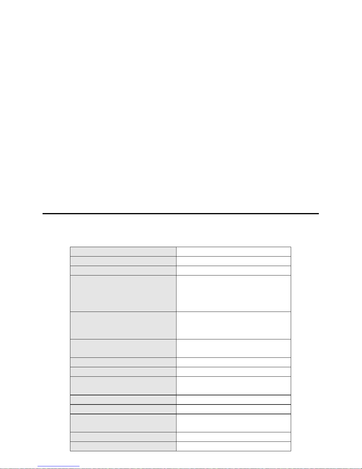
SPECIFICATIONS
XT
-
15
Sub
Frequency Response:
40 Hz
–
120
Hz
Coverage Pattern:
EssentiallyO
mnidirectional
Input/Thru Connections:
Both input and output on
3
-
Pin XLR
-
type
(Pin 2 +)
Line level output High Pass 120Hz
Power:
Peak - Total System:
Continuous-
Total System:
1,200 Watts
600 Watts
AC Mains Power: Manual
Switching
115VAC /230V
AC
(50 Hz – 60 Hz)
Input to achieve rated output:
0.774
V RMS
(line level)
Max Acoustic Output (Peak):
126 dB*
Input Section Control:
Output gain
Polarity control
Rigging:
None
included
Supplied Accessories:
AC Mains Cable
Dimensions (H X W X D):
545 X 420X 579mm
21.5 X 16.5 X 22.7 inches
Weight (kg / lb):
35 kg / 77.2 lbs
Operating temperature (C/F) :
0C
-
43C / 32F
-
110F
* NOTE: Max Acoustic Output is based on smoothed system response, not peak driver
response.
P.Audio is continually looking to improve products, so specifications are subject to change
without notice.
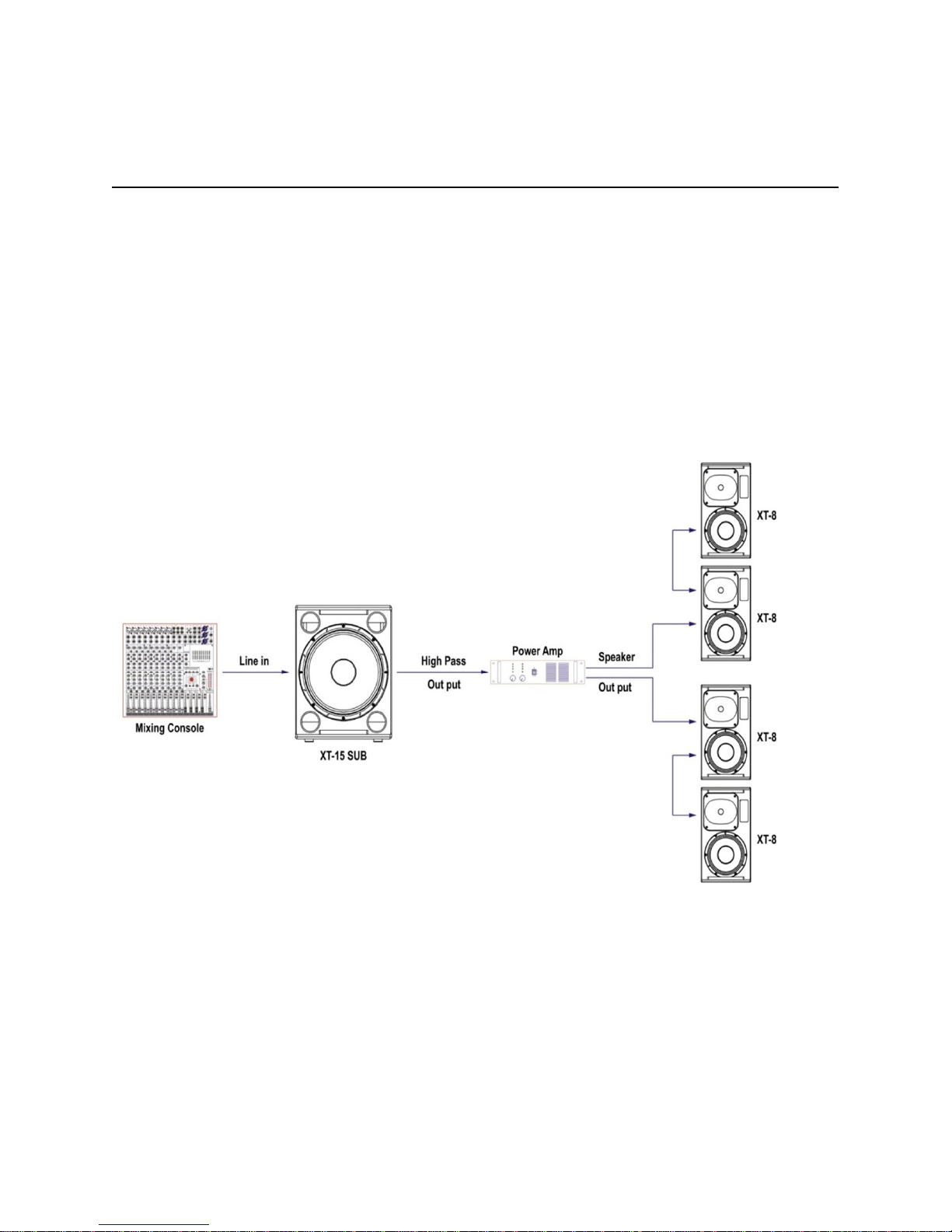
FEATURES AND APPLICATIONS
The XT-15Sub can be used in a wide range of scenarios, whether fixed install or portable live
sound or speech reinforcement. The XT Series excels in commercial sound reinforcement,
where a powerful, yet compact and discrete sound system is required. Some examples of use
are shown below.
1. Fixed install: 1 XT-15Sub with multiple XT-8 enclosures.

2. Portable sound reinforcement: 2 XT-15Sub with 2 XT-10
SETUP AND USE OF THE XT-15Sub
NOTE: The XT-15Sub uses a switchable AC Mains power supply. It is the
responsibility of the user to insure that the AC mains are set to the correct AC
voltage. This voltage is either 115VAC or 230VAC. The correct setting depends
on the specific country and AC mains voltagein that country.
NOTE: Check voltage selector and fuse are correct for the specific country
and voltage in that country. For use in countries that provide 115V AC Mains,
the fuse must be 10A, 250v, SLOW BLOW fuse. For use in countries that
provide 230V AC Mains, the fuse must be 5A, 250v SLOW BLOW fuse. The
extra fuse is located in the spare fuse holder in the AC input section.
AC MAINS CONNECTION

Prior to connecting the AC mains cable, ensure that the AC mains switch is in the OFF position.
The XT-15Sub will operate on AC mains voltages of 115 volts OR 230 volts. The required AC
mains frequency is between 50 Hz and 60 Hz. The acceptable voltage range is 104VAC-
126VAC and 207VAC-253VAC. Please insure that the correct fuse value is also installed (See
comments inthe“SETUP AND USEOF THE XT-15Sub” section above)
NOTE: This voltage MUST be set by the user prior to connecting the AC mains cable.
The specific voltage, either 115VAC or 230VAC, will be determined by the AC mains
specific to the country where the product is being used. The correct fuse value must
also be inserted!
The XT-15Sub uses a standard IEC-type AC mains connector system. To mate the AC mains
cable with the AC mains connector on the amplifier, simply align the plug with the panel’s
connector and press the AC mains cable into place. Always support the enclosure with one
hand whilst performing this operation. The AC mains connector is shown above. To disconnect
the cable end of the AC mains connector pull back on the molded plug at the end of the cable,
not the cable itself.
NOTE: ALWAYS turn off the AC mains power BEFORE attempting to disconnectthe
AC mains cable from the XT-15Sub amplifier module!
NOTE: DO NOT CONNECT THE AC MAINS END OF THE AC MAINS CABLE IN
AN AREA THAT IS WET OR SUBJECT TO CONDENSATION OR DAMP
CONDITIONS!
Once the AC mains cable is securely connected to both the amplifier and AC mains supply, the
amplifier may be turned on. It is good practice to make certain that the audio levels on the
mixer’s output (or other source output) are reduced or muted prior to applying power. The pilot
light is located on the rear panel.
NOTE: If the pilot light does not illuminate within 30 seconds the unit may be in a
FAULT CONDITION. If this occurs, the unit should be returned to P.Audio for
evaluation.
THERE ARE NO USER-SERVICABLE PARTS INSIDE. DO NOT REMOVE THE
AMPLIFIER MODULE! (See the section below “Replacement of Components” for
more detailed information).
AUDIO CONNECTIONS
The XT-15Sub amplifier includes both male and female XLR-type connectors. Any standard
XLR-type cable end connectors maybe used.
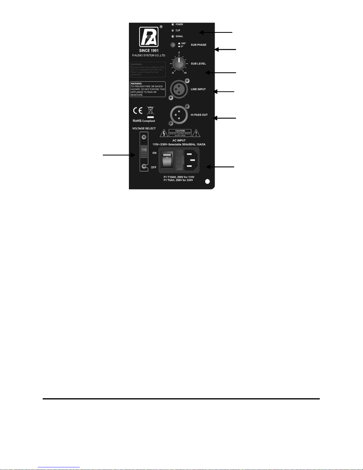
The image below illustrates the XT-15Sub input plate. Both the audio input and audio high-pass
output connectors are shown.
Power/Signal/Clip
LED’s
The input connector should be used for the MAIN full-range audio input signal and the High-
Pass Filtered Output should be connected to the associated mid-hi speakers. The High-Pass
Filtered Output has a 4th order, 24 dB-per-octave filter at 120 Hz. All program material between
40 Hz and 120Hz is routedtotheXT-15Sub’s internal amplifier. Any professional-grade XLR to
XLR cable may be used for this wiring. In all cases, pin 2 on the XLR connector is the positive
terminal.
The XT-15Sub also features a Sub Gain control that allows the output level of the subwoofer to
be set to match the acoustic level of the associated mid-hi speaker. This feature may be
adjusted to suit individual music styles and room acoustics. The XT-15Sub also includes both a
clip indication led and a signal present led. The XT-15Sub amplifier should be monitored to
ensure that the clip indicator is not active. If the clip indicator is active the input gain or EQ from
the mixer should be reduced.
The XT-15Sub features a polarity reversal switch that is located directly above the sub gain
control on the input panel. When the top box is placed on a pole and located directly above the
XT-15Sub the polarity switch should be in the 0 degree (“normal”) position. For applications
where the top box is not directly above the XT-15Sub the polarity switch may be changed. The
optimal configuration requires experimentationand is based onthephysical separation between
the sub and top box. (i.e., if thetop boxis behind or infront of the sub).
On/Off Switch,
Fuse Holder and
IEC Power Inlet
Hi Pass Output
with120Hz High
Pass filter
XLR LineInput
Output Level
Voltage Selector
Switch
Phase reversal
switch

RIGGING AND SUSPENSION
The X9 Sub is intended to be used with a standard M20 screw thread style satellite pole mount
(available from P.Audio) for mounting the XT-8 or XT-10 above it. The XT-15Sub MUST be
located on a level surface that is capable of safely supporting the weight of both the XT-15Sub
and the XT-8 or XT-10.
WARNING: The pole used to mount the XT-8 or XT-10 must NOT be more than 1.25
meters (49 inches) long. DO NOT use a pole that is longer than 1.2meters! DO NOT
PLACE ANY OTHER LOUDSPEAKERS, EXCEPT THE XT-8 or XT-10 on the XT-
15SUB’S POLE.
WARNING: DO NOT ATTEMPT TO SUSPEND P.AUDIO PRODUCTS WITHOUT
UNDERSTANDING LOCAL AND NATIONAL CODES THAT APPLY TO OVERHEAD
SUSPENSION OF PRODUCTS.
DO NOT ATTEMPT TO SUSPEND P AUDIO PRODUCTS UNLESS YOU ARE A
PROFESSIONAL WITH KNOWLEDGE OF LOCAL AND NATIONAL CODES
RELATED TO SAFE SUSPENSION AND ARE EXPERIENCED IN SUSPENDING
PRODUCTS OVERHEAD.
P.AUDIO IS NOT RESPONSIBLE FOR FAILURES RELATED TO NON-COMPLIANCE WITH
LOCAL AND NATIONAL CODES AND SAFE SUSPENSION PRACTICE. ALL ASSOCIATED
RIGGING IS THE RESPONSIBILITY OF OTHERS.
APPLICATION AND TROUBLE SHOOTING TIPS
The XT Series products make up a series of high-quality professional sound reinforcement
systems designed for use in both indoor, and dry outdoor applications. Some basic precautions
will insure long-term reliability.
EQUALIZATION AND GAIN
The XT-15Sub has all the required equalization and gain functions included in the internal
analog signal processing circuits. Both the equalization and gain functions have been optimized
for best bass output, flat frequency response and maximized system dynamics.
The system gain may be set by the on-board gain functions as well as any outboard mixing
console gain and EQ functions. If distorted sound is heard the gain and EQ settings on BOTH
the XT-15Sub amplifier and the outboard mixer should be carefully checked to ensure that the
input sectionof the XT-15Sub is not overloaded.
PROBLEM: Distorted sound
When input levels to the XT-15Sub amplifier exceed 0.775 V RMS it is possible to produce
system clippingor overdrive. It is still possible to “overdrive” the input section of the enclosure. If
distorted soundis present the following stepsshould betaken:
1. Verify that the mixer’s output is not clipping or overloaded. If the output metering
section of the mixing console is continuously in the “red” then the output level should
be reduced. (occasional “red” indications are usually fine and are dependent on the
mixing console’s output capability).
2. Verify that excessive equalization is not present anywhere in the signal chain.
3. Verify that AC mains levels are within the required range.
Voltage measurements on the AC Mains should be performed by a licensed
electrician or individual trainedin making high-voltage measurements.
PROBLEM: No sound
1. Verifythat theamplifier pilot light is on.
2. Verify that there is AC Mains voltage on the AC Mains input to the amplifier.
3. If AC Mains voltageis present, verifythat the fuseis not blown.
4. Verify that the correct fuse is inserted. Guidelines for this can be found earlier in this
manual, and on the amplifier panel itself.
NOTE: IF THE FUSE IS BLOWN REPLACE ONLY WITH THE SAME TYPE OF
FUSE. THIS FUSE TYPE IS NOTED ON THE INPUT PANEL NEAR THE FUSE
HOLDER.
PRODUCT SERVICE
There are NO user-serviceable parts inside theXT-15Sub amplifier.
The X9 amplifier moduleMUST be serviced by a company authorized by P. Audio.
Replacement of Components
REPLACEMENT OF COMPONENTS MUST BE PERFORMED BY A QUALIFIED
TECHNICIAN OR ONE KNOWLEDGABLE IN THE REPLACEMENT OF
TRANSDUCER COMPONENTS!
DO NOT ATTEMPT ANY REPAIRS UNLESS THE XT-15Sub AMPLIFIER HAS
BEEN DISCONNECTED FROM THE AC MAINS SOURCE!
In the event of woofer failure, the woofer may be accessed by removing the front grille and then
removing the woofer. This should be done by a qualified technician or contractor. There is no
need to removethe amplifierpanel in the event of awoofer failure.
USE EXTREME CARE WHEN HANDLING THE XT-15Sub AMPLIFIER MODULES.
THE COMPONENTS ARE FRAGILE AND THE MODULE MUST NOT BE SET
DOWN ON THE COMPONENT SIDE OR DAMAGEWILL OCCUR!
Care should be exercised when disconnecting the amplifier module from the woofer. Be sure to
observe the wiring polarity ofthewoofer.
Thank you once again for purchasing this P.Audio product. P.Audio is a manufacturer of a
complete range of Loudspeaker systems, individual components and accessories. For more
information regarding any of P.Audio’s products or advice on how to set up and use this
product, pleasedo not hesitateto usethecontact details belowtocontact us.

Please scan this QR code for quick access
to the P.Audiowebsite.
P Audio System Co., Ltd. 19/4 Moo 2 T.Bangkratuk
A.Samparn , Nakornpathom. 73210,Thailand
Tel: +66-2-441 6600 (Auto30 Lines) Fax: +66-2-441 6699
Website: www.paudiothailand.com
E-mail: info@paudiothailand.com
Table of contents
Other P.Audio Subwoofer manuals


Popular Subwoofer manuals by other brands


Garmin
Garmin FUSION SIGNATURE Series installation instructions

JL Audio
JL Audio Stealthbox SB-GM-CAM6G/12TW3 installation guide

Saga
Saga The Queen SAG0206SUB user manual

Snell
Snell ICS Sub 24 mk3 owner's manual

Snell
Snell Premier Basis 300 owner's manual

Atlantic Technology
Atlantic Technology 642e SB instruction manual


