P. M. Lighting Professional CS Series User manual


CS936-LED Copper Area/Path Lights†
Landscape Cable 14/2 gauge*
CS937-LED Copper Bullet Directional Lights†
1 each Outdoor Timer with Photocell
CS933-LED In-Ground Well Lights‡
1 each Stake Driver Cap (Installation Tool)
1 each CS Pro-Series Transformer
Screwdriver (Flat & Phillips Head)
Shovel
Wire Cutter
Hammer
Wire Stripper
100-Ft Measuring Tape
Pliers
Power Drill and Bits (3/16” bit for plastic anchors)
Dead Blow Mallet (for stake installation)
Gloves
Determine the location of the power transformer before installation and make sure a suitable 115/120VAC
covered GFCI outlet marked “WET LOCATION” is within reach of the transformer power cord. Attach and
secure transformer to the wall a minimum of 12 inches above ground using screws and anchors (if needed).
Mounting screws are provided for your convenience.
Lay out the 14/2 gauge MAIN SUPPLY CABLE according to the Easy Design Guide on the next page, paying
close attention to where your fixtures are located and distances to determine the length of cable needed.
Install each luminaire according to the individual instruction sheets, attach each luminaire to the Main
Supply Cable using the attached easy connectors, and bury loose cable as desired (6 inches deep or less).
Plug Power Transformer into the Timer with Photocell, plug the timer into the GFCI outlet, and turn the
Timer dial to the desired setting for Dusk/Dawn, or Dusk On/ Off in 2, 4, 6, or 8 hours.

Use the Easy Design Guide to help determine the best way to wire your fixtures to create optimal results in the
illumination of your home. Follow these simple rules for best results:
1. It is recommended that you use 2 MAIN SUPPLY CABLE runs from the transformer for best results and
easiest installation, especially when you need to install fixtures on both sides of the transformer.
2. For short distances from the transformer (under 60 feet), only a single MAIN SUPPLY CABLE may be used to
install this LED system for even easier installation. If the transformer is located on one end of the house,
simply run a cable from the transformer to the various lights, leaving a little extra slack to make burying the
cable easy.
3. DO NOT EXCEED the MAXIMUM WATTAGE listed for each length of MAIN SUPPLY CABLE used or the
voltage at the fixtures will be lower than required causing the LED to flicker or not light at all. If any lights,
especially on the end of the MAIN SUPPLY CABLE, do not light or experiences flickering, make sure the
transformer is on the HIGH setting (See #4 below) and check to make sure the quick connectors on each
light fixture are properly installed and are making a good connection.
4. SHORTER lengths for the MAIN SUPPLY CABLE lowers voltage drop on the line while LONGER lengths
increases the voltage drop. Use the Line Length/Wattage Chart below to determine the maximum wattage
load for various lengths of the MAIN SUPPLY CABLE.
5. The total wattage for the CS Pro Series systems range from just 30 watts for the CS6100-LED 6 light kit to
50 watts for the largest CS12100-LED 12 light kit , providing ample room on the standard 100 watt
transformer to add additional CS Professional Series LED fixtures to expand your system. The chart below
will help determine the maximum amount of fixtures you can have on the system when you add up the total
wattage from all fixtures on the line / system.
Total Length of Main
Supply Cable
Maximum Wattage
Available for Fixtures
CS Professional Series
LED Fixtures
Individual Fixture
Wattage
50 Feet
90 watts
CS936-LED Path Light
3.0 watts
60 Feet
75 watts
CS937-LED Bullet Light
5.0 watts
70 Feet
60 watts
CS938-LED Deck Light
2.0 watts
80 Feet
55 watts
CS933-LED Well Light
6 watts
90 Feet
50 watts
*Quantity and type of fixtures will vary by model of
100 Feet
45 watts
Kit purchased. See product label for more details.

This example demonstrates the optimal wiring plan design, using
two (2) Main Supply Cables from the transformer to split the
fixtures into two (2) groups. For best results follow these tips:
1. Keep cables as short as possible.
2. Leave enough slack to make burying cable easier.
3. Make sure the Easy Connectors are tight to create a good
connection on the Main Supply Cable

Save these instructions!
For use with Low Voltage Landscape Lighting Power Units. FOR OUTDOOR USE ONLY.
Amperage not to exceed 25 AMPS per circuit
Voltage not to exceed 15 VOLTS per circuit
Warning: Luminaire must be installed in accordance with the National Electric Code (NEC) and all Local Codes. Failure
to comply with NEC and/or Local Codes may cause serious injury and could destroy the luminaire. Failure to comply
with NEC and Local Codes will void all warranties.
Safety Warning: LAMP IS HOT WHEN LUMINAIRE IS ON! Hot lamp creates risk of fire and injury to persons. Keep away
from combustibles. Lamp gets hot very quickly. Turn off or unplug luminaire and allow lamp to cool to change bulb.
Do not touch lamp with bare hands. When using this fixture with high wattage halogen lamps (35W halogen
MAXIMUM), keep luminaire away from children as luminaire may become VERY HOT. Do not install luminaire within
10 feet (3.05 meters) of a pool, spa, fountain, or pond. Do not cover or bury luminaire and keep luminaire clear of
debris. Use only UL compliant components including low-voltage power units, cable, wire connectors, and any other
component necessary. CAUTION: Luminaire is NOT submersible!
NOTE: Do not exceed the maximum wattage rating or maximum amperage rating of the power unit (transformer)
used when installing multiple luminairies.

Save these instructions!
For use with Low Voltage Landscape Lighting Power Units. FOR OUTDOOR USE ONLY.
Amperage not to exceed 25 AMPS per circuit
Voltage not to exceed 15 VOLTS per circuit
Warning: Luminaire must be installed in accordance with the National Electric Code (NEC) and all Local Codes. Failure
to comply with NEC and/or Local Codes may cause serious injury and could destroy the luminaire. Failure to comply
with NEC and Local Codes will void all warranties.
Safety Warning: LAMP IS HOT WHEN LUMINAIRE IS ON! Hot lamp creates risk of fire and injury to persons. Keep away
from combustibles. Lamp gets hot very quickly. Turn off or unplug luminaire and allow lamp to cool to change bulb.
Do not touch lamp with bare hands. When using this fixture with high wattage halogen lamps (35W MAXIMUM), keep
luminaire away from children as luminaire may become VERY HOT. Do not install luminaire within 10 feet (3.05
meters) of a pool, spa, fountain, or pond. Do not cover or bury luminaire and keep luminaire clear of debris. Use only
UL compliant components including low-voltage power units, cable, wire connectors, and any other component
necessary. CAUTION: Luminaire is NOT submersible!
NOTE: Do not exceed the maximum wattage rating or maximum amperage rating of the power unit (transformer)
used when installing multiple luminairies.

For use with Low Voltage Landscape Lighting Power Units. FOR OUTDOOR USE ONLY.
Amperage not to exceed 25 AMPS - Voltage not to exceed 15 VOLTS
Warning: Luminaire must be installed in accordance with the National Electric Code (NEC) and all Local Codes. Failure
to comply with NEC and/or Local Codes may cause serious injury and could destroy the luminaire. Failure to comply
with NEC and Local Codes will void all warranties.
•Low voltage cable shall be protected by routing in close proximity to the luminaire or fitting, or next to a
building structure such as a house or deck and have the length cut off so that it is connected to a connector
within 6 inches (15.2 cm) from a building structure, a luminaire, or fitting.
•When ordering additional wire or cable, please contact the manufacturer customer service or contact a
qualified electrician.
Safety Warning: LAMP IS HOT WHEN LUMINAIRE IS ON! Hot lamp creates risk of fire and injury to persons. Keep away
from combustibles. Lamp gets hot very quickly. Turn off or unplug luminaire and allow lamp to cool to change bulb.
When using high wattage lamps, keep luminaire away from children, as luminaire may become VERY HOT. Do not
install luminaire within 10 feet (3.05 meters) of a pool, spa, fountain, or pond. Do not bury luminaire below the
recommended depth and keep luminaire clear of debris. Use only UL compliant components including low-voltage
power units, cable, wire connectors, and any other component necessary. CAUTION: Luminaire is NOT submersible!
NOTE: Do not exceed the maximum wattage rating or maximum amperage rating of the power unit (transformer)
used when installing multiple luminaires. NOT FOR USE WITH DIMMERS!


CS Pro Series Transformer
Installation Instructions
The CS ProSeries Transformer must be plugged in to a 120VAC GFCI protected outlet. Unplug transformer
from outlet prior to installation and during service!
For all wire connections: Use UL listed Wire Connectors included with the fixtures and kit.
For all the opened knockouts: Use UL listed Cable Clamp suitable for the cable size and type (included with
kit).
Please check that the total lamp/fixture wattage does not exceed 100 Watts (or 150 Watts for the CS150T
transformer). For optimal performance, use 80% of the maximum for lamps/fixtures (80 watts or 120 watts
for the CS150T transformer)
Ensure that the overload protector switches under the terminal block are reset (pushed in) and not tripped
for any reason.
MOUNTING
Choose the best location on any rigid vertical wall or post within easy reach of the 120VAC GFCI Outlet,
making sure that the wiring compartment is facing down and at the bottom. Transformer should be mounted
a minimum of 12 inches above ground.
Open the wiring compartment cover by pulling outward on the cove to swing it up to the open position.
The enclosures have a knockout on the bottom of the housing for the low-voltage cable to enter through a
cable clamp and the opening. Install included cable clamp into the knockout hole before adding cables from
fixtures.
GROUNDING
The transformer case must be grounded. Check to see if the green ground wire from the power cord is
properly secured to the transformer housing by the ground nut. This was done at the factory so there should
be no action needed by the end user / consumer.
OUTPUT CONNECTIONS –(One 12V output circuit) 100 watts (or 150 watts for CS150T transformer)
Bring the 12V lamp wires into the wiring compartment through the open knockout/cable clamp and connect
each side to the BOTTOM terminal block lug screws. The lug screws of the terminal block should be secured
tight to create a solid connection. Tighten screws on the cable clamp to secure the cables into the housing.
INPUT CONNECTION
This transformer is designed for use with standard 120V 60Hz power.
Plug the power cord into a standard 120VAC, GFCI protected outlet.
Please check and make sure you have followed all installation instructions carefully!

To further clarify installation and wiring of your CS Professional Series power transformer, please refer to
the instructions below.
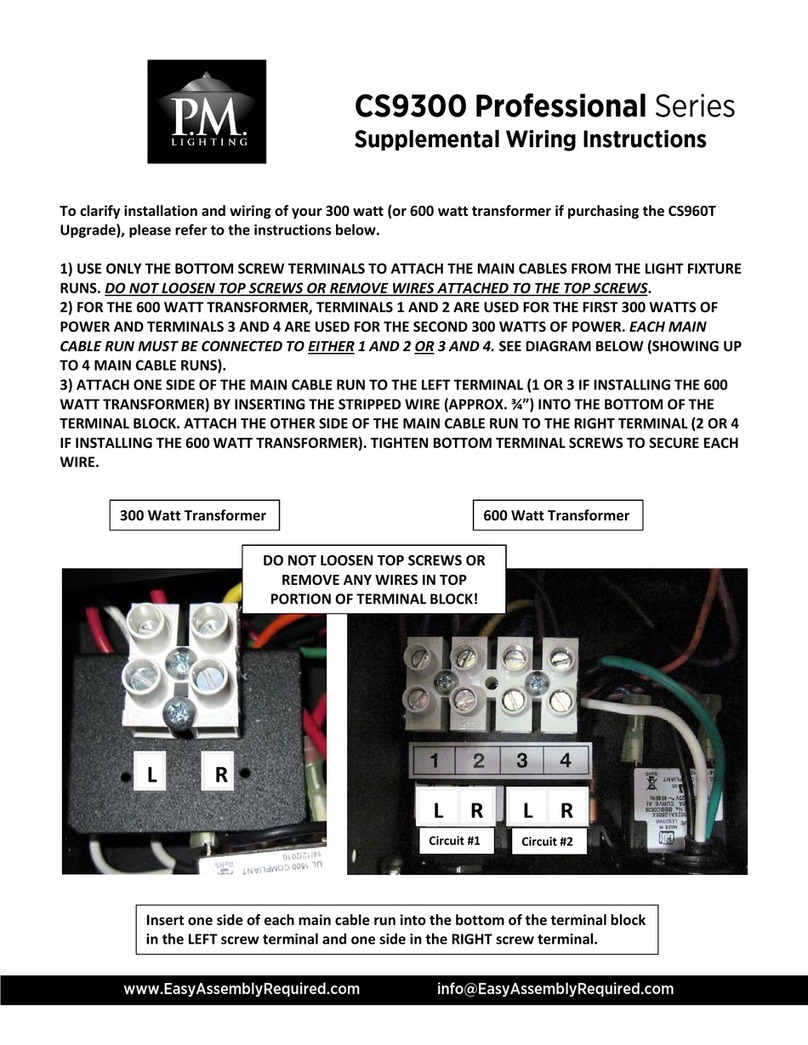
1) USE ONLY THE BOTTOM SCREW TERMINALS TO ATTACH THE MAIN CABLES FROM THE LIGHT FIXTURE
RUNS. DO NOT LOOSEN TOP SCREWS OR REMOVE WIRES ATTACHED TO THE TOP SCREWS. LOOSENING
THE TOP SCREWS MAY CAUSE THE TERMINAL BLOCK TO LOSE POWER TO THE TRANSFORMER COIL.
2) EACH MAIN CABLE RUN MUST BE CONNECTED TO 1 (LEFT) AND 2 (RIGHT). SEE DIAGRAM BELOW
3) ATTACH ONE SIDE OF THE MAIN CABLE RUN TO THE LEFT TERMINAL (1) BY INSERTING THE STRIPPED
WIRE (APPROX. ¾”) INTO THE BOTTOM OF THE TERMINAL BLOCK. ATTACH THE OTHER SIDE OF THE
MAIN CABLE RUN TO THE RIGHT TERMINAL (2). TIGHTEN BOTTOM TERMINAL SCREWS TO SECURE EACH
WIRE.
Transformer Terminal Block
Insert one side of each main cable run into the
bottom of the terminal block in the (1) LEFT
screw terminal and one side in the (2) RIGHT
screw terminal.
CAUTION: DO NOT LOOSEN TOP
SCREWS OR REMOVE ANY WIRES IN
TOP PORTION OF TERMINAL BLOCK!
1L
2R

• Each 14/2 main cable must be split in the middle to create a left and right side.
•Strip the outer insulation from each wire approximately ¾” of an inch to expose the copper
stranded wires
Left
Wire
Right
Wire
Strip Length
Approx. ¾”
• For a single home run cable, twist the strands of copper wire together tightly for each side.
•For more than one home run cable, twist the strands of copper wire together, combining each
side together tightly as shown in #5 to make a completed wire harness. Make sure the left and
right sides of each cable are separated.
Left
Wires
Right
Wires
Two (2)
Main
Cables

This manual suits for next models
15
Table of contents
Other P. M. Lighting Outdoor Light manuals