Pacbrake Inline Mount User manual


INLINE MOUNT Exhaust Brakes
INSTALLATION MANUAL - L2031 PG. 2
Getting Started
Thank you and congratulations on your purchase of a Pacbrake Inline Mount®exhaust brake kit.
Before starting, be sure you have attained the proper brake, mounting kit and control group for your vehicle.
Below is a sample of all the parts needed for installation.
*Some models require back pressure adjustment.
For these models a gauge kit is required.
PN C10600.
Verify the vehicles exhaust pipe size is correct for the adapt-
ers supplied.
NOTE: The adapters are expanded to slide over the
existing exhaust pipe. Pacbrake adapters are avail-
able for all standard exhaust pipe sizes. Compare
the exhaust pipe OD against the adapter I.D. before
cutting the exhaust pipe.
1With the exhaust brake on the bench, loosely attach the ex-
haust pipe adapters provided, and make a measurement to
determine the length of vehicle exhaust pipe to be removed.
The adapters are expanded to slide over the existing exhaust
pipe—consider this in your measurement
2Select a location that has sufficient clearance for installation
and servicing of the exhaust brake. This location should be
as close to the turbocharger as possible and away from dirt
and road spray. Keep in mind that Exhaust Brakes subjected
to road spray will shorten the life and require a Remote Cyl-
inder Breather Kit PN# C11020. Transfer the brake/adapter
measurement to this location and mark the exhaust pipe.
Remove the exhaust pipe and cut the pre-marked section.
NOTE: In some cases, the cutting and welding of ex-
haust systems can be done without removing the pipe
sections from the vehicle.

INLINE MOUNT Exhaust Brakes
INSTALLATION MANUAL - L2031 PG. 3
3Clamp exhaust brake and exhaust system in place and tack
weld prior to final welding. Weld the adapters to the sections
of pipe, being careful to maintain the proper length and
angles that exist. Welding can be done on the outside or the
inside of the adapter, but it must be leak free.
NOTE: Clamped joints that exist between the brake
and the engine must also be welded at this time to
ensure the joint cannot separate or leak under pres-
sure.
4If removed, reinstall the front section of pipe on the engine.
Torque turbo clamp to engine manufacturers specification.
Center brake and tighten clamp on the exhaust brake pres-
sure side. Install the rear section of pipe and loosely clamp.
Check alignment of all sections and joints and torque “V”
clamps to 10 FT.LBS.
5Select a location to mount the 12V compressor assembly.
Mounting can be in any position. The location should be free
of heat and contamination and must provide the compres-
sor a good electrical ground by attaching the compressor
grounding wire to a good ground source.

INLINE MOUNT Exhaust Brakes
INSTALLATION MANUAL - L2031 PG. 4
6Prior to mounting the compressor, attach the air filter to the
intake port and firmly tighten by hand. Attach the rubber
mounting feet to the compressor mounting brackets using
the grommets and grommet sleeves provided. These will
isolate the compressor from vibration
NOTE: A remote breather kit for compressor intake air
must be used if dust or road spray is present near the
air intake filter. Pacbrake P/N C11620 is available and
must be ordered separately. (shown in diagram)
7Route the Teflon air hose from the compressor assembly to
the fitting on the air cyclinder.
Cut the hose and make the connection, being careful that the
hose is secured away from any heat that could damage it.

INLINE MOUNT Exhaust Brakes
INSTALLATION MANUAL - L2031 PG. 5
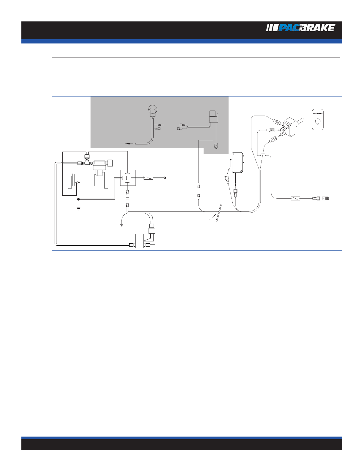
Wiring Schematic Index
* 1998-2002 Ford Econoline Vans equipped with Powerstroke, see wiring schematic on page 6
* Pre-1998 Ford Econoline Vans Equipped with Powerstroke, see wiring schematic on page 9
* Navistar vehicles equipped with 444E, see wiring schematic on Page 13
* 1999-2002 Dodge 24 Valve Electronic equipped with Cummins 5.9/ISB, see wiring schematic on page 14
* Pre 1999 Dodge 12 Valve Mechanical equipped with Cummins 5.9, see wiring schematic on page 16
Application Guide
Engine
Max.
Backpressure @RPM
Exhaust
Brake
*C10300 model is an adjustable brake
and must be set during a road test
using a backpressure gauge. Due
to upgrades and variations between
engines (i.e: different turbo chargers) it
is not possible for Pacbrake to provide
a preset brake to cover all possibilities.
Econoline or Ford Powerstroke 32 PSI 3400 C20366
Dodge Cummins 5.9L 35 PSI 3100 *C10300
Dodge Cummins 5.9L
(with heavy duty valve springs)
60 PSI 3100 *C20369
Dodge Cummins 24 valve 60 PSI 3100 *C10300
International 444E 32PSI 3400 *C20366
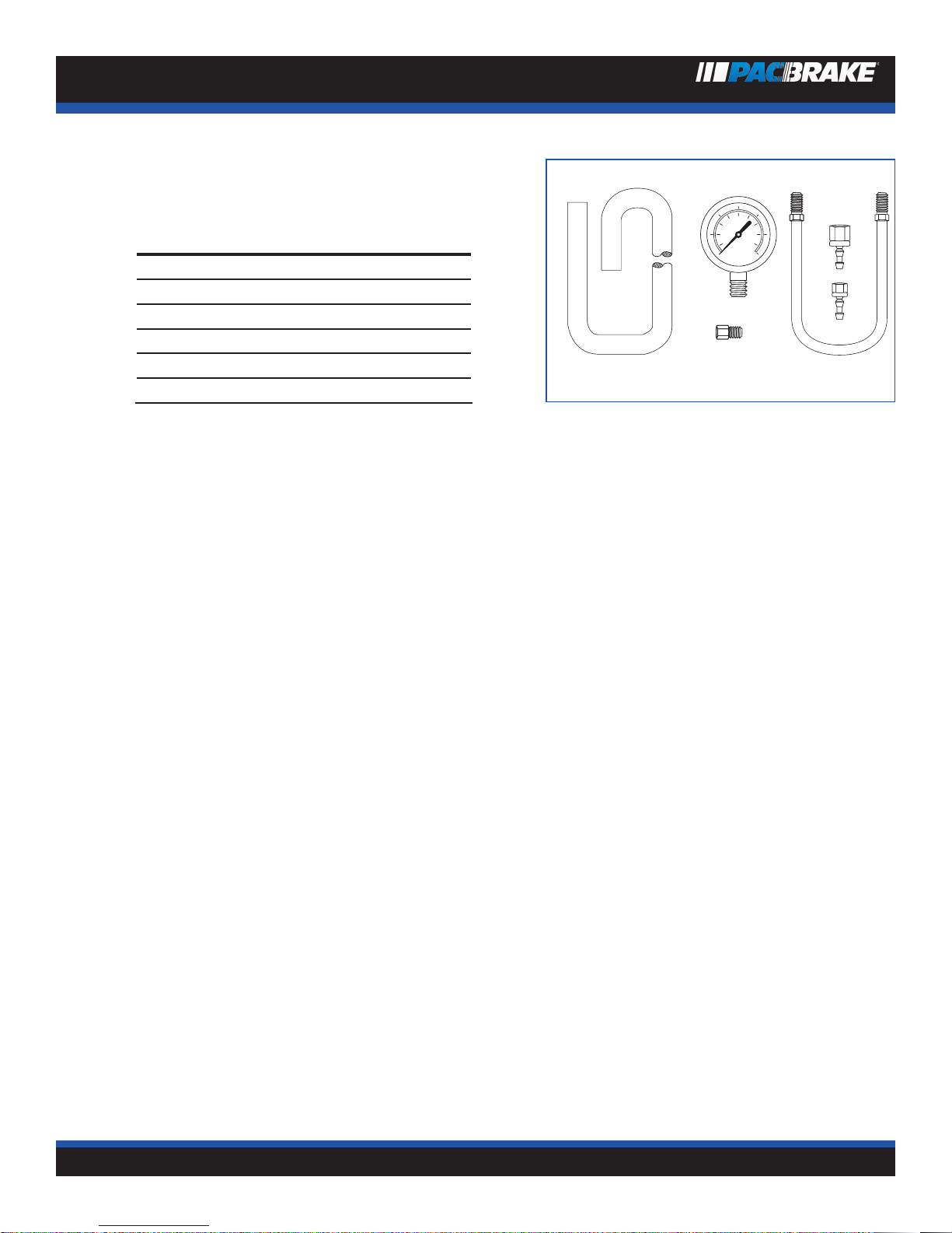
Testing Exhaust Brake Back Pressure
Prepare for road test check or set exhaust brake back pressure. Pacbrake test gauge kit PT# C10600, can be purchased through
the Pacbrake distribution system. This kit contains all the necessary parts to perform back pressure tests. The gauge used must be
a dampened (liquid filled) type to accurately read this pressure.
1. Remove the 1/8” NPT plug located in the exhaust brake body and install fitting #3. Install the steel tube #4 into the fitting
installed in the exhaust brake. Instert fittings #5 and #6 into the neoprene hose, moistening the fittings and firmly pushing
the hose onto the barbed end. Install one end of the hose to the steel tube and the other to the gauge. Tighten all fittings
securely. Route neoprene hose into cab.
Note: This test must be performed to ensure engine manufactures back pressure specifications are not ex-
ceeded - check the application guide for the correct maximum allowable PSI setting at governed speed.
2. Warm the engine to normal operating temperature.
3. Road test the vehicle by providing long durations of maximum RPM with the exhaust brake applied. This is best achieved
with weight in the vehicle and a downhill grade.
4. .Read and record the pressure achieved on the gauge at the governed engine speed. Pacbrake inline models have an
adjustable stop bolt to adjust exhaust back pressure, This is done by the stop screw which limits the activating arm travel,
thus reducing back pressure.

INLINE MOUNT Exhaust Brakes
INSTALLATION MANUAL - L2031 PG. 6
C10600 Test Gauge Kit
1
2
3
4
5
6
must be ordered separately
Illus.No. Part No. Description Qty
1 C10650 Gauge 1
2 C10800 Hose 1
3 C10678 Fitting 1
4 C10677 Steel Tube 1
5 C10676 Fitting 1
6 C10775 Fitting 1

INLINE MOUNT Exhaust Brakes
INSTALLATION MANUAL - L2031 PG. 7
EXHAUST BRAKE WIRING SCHEMATIC
1998-2002 Ford Trucks and Econoline Vans
Equipped With Powerstroke
Ford® Brake Pressure switch
Blk./Yel. Blue
Red
Dash
switch
OFF
Red
Red
Red
Red
To IVS
Ground
Red
Black
15 Amp
Fuse
12V+
Ignition
Switched
Green
Black
Firewall
Blk./Yel.
To Ford® PCM
Blue
Cruise
Relay
Green
NOTE:
SHADED AREA
APPLIES TO
CRUISE
CONTROL
VEHICLES
86 87
85
30 87a
Red
Ground
Relay
Air Intake
Filter
20 Amp
Fuse
Connect to
positive battery
terminal
87
30
87a
85 86
Black
Yellow
Red
Green
To Brake
Green
THROTTLE RELAY INSTALLATION
At the throttle pedal, locate the I.V.S. (Idle Validation Switch).
NOTE: The IVS connection is critical and must be correct. We recommend using a 12 volt test light to verify the cor-
rect wire BEFORE installing the “T” tap.
Most common for vehicles built after 10/2000 is a red wire with a green stripe 2nd from the top of the connector, however because
of possible production changes, using a test light is the only way to be sure. With the ignition on, probe this wire with the test light
first as it should be 12 volt positive with the accelerator pedal to the floor. Release the pedal and the light should go off. If this is
correct connect this wire as explained below, if not, probe the remaining wires until you locate the one which has 12 volts positive
with the accelerator pedal depressed and no current with the pedal released.
With the correct wire selected, use the blue electrical “T” tap supplied and tap into this wire. Plug the insulated male end of the 12”
yellow wire into the “T” tap. Connect the opposite end of the yellow wire to terminal 86 of the supplied relay. Connect the 12” black
wire to terminal 85 of the relay and find a good vehicle ground for the eye terminal on the opposite end.
Connect the two red harness wires to terminals 30 and 87A and then secure the relay to existing wiring (in this location) with the
tystraps provided.

INLINE MOUNT Exhaust Brakes
INSTALLATION MANUAL - L2031 PG. 8
1998-2002 Ford Trucks
and Econoline Vans with
Powerstroke
1For vehicles WITHOUT cruise control, omit steps 1 & 2.
Remove the ground strap bolt on the driver-side of the
firewall and install the relay receptacle and relay ground wire
on this bolt.
Install relay into the receptacle.
2Ford installs a brake pressure applied switch on the front
lower side of the master cylinder.
Locate the black wire with a yellow stripe. Cut this wire and
crimp on the two red terminals provided. Connect these to
the mating terminals of the two remaining blue wires coming
from the relay harness.
Neatly secure all wiring with the plastic ties. Connect the
wiring harness to the solenoid and to the cruise relay.
3Remove the lower instrument panel (see arrow). Drill a 1/2”
hole as shown for the dash switch. The dash switch location
is a suggestion only.
Install the Pacbrake on/off switch. Connect the two wiring
harnesses to this switch, observing the correct wire and
terminal locations as shown in the wiring schematic.
Switch location can vary depending on customer choice or
the availability of space. Choose a location which is conve-
nient to the driver. Pacbrake offers a transmission gear lever
mounted on/off switch for manual transmission equipped
vehicles.
4Locate a 12 volt ignition power source in the harness directly
below the steering column (see arrow).
Attach the yellow T-tap connector to this wire which should
be 12V+ ignition switched.

INLINE MOUNT Exhaust Brakes
INSTALLATION MANUAL - L2031 PG. 9
EXHAUST BRAKE WIRING SCHEMATIC
Pre 1998 Ford Trucks and Econoline Vans Equipped With
Powerstroke
Ford® Brake Pressure switch
Blk./Yel. Blue
Red
Dash
switch
OFF
Red
Red
Red
Red
Red
Black
15 Amp
Fuse
12V+
Ignition
Switched
Green
Black
Firewall
Blk./Yel.
To Ford® PCM
Blue
Cruise
Relay
Green
NOTE:
SHADED AREA
APPLIES TO
CRUISE
CONTROL
VEHICLES
Red
Ground
Relay
Air Intake
Filter
20 Amp
Fuse
Connect to
positive battery
terminal
87
30
87a
85 86
Red
Green
To Brake
Throttle
Switch
Green

INLINE MOUNT Exhaust Brakes
INSTALLATION MANUAL - L2031 PG. 10
Pre 1998 Ford Trucks and
Econoline Vans with
Powerstroke
1For vehicles without cruise control, omit steps 1 -2. Remove
the relay and mount the receptacle of the C11971 harness to
the firewall, including the green ground wire, with the screw
supplied. Replace the relay. Connect both harnesses together
using the remaining red wire.
2“Ford” installs a Brake Pressure Applied Switch on the TOP
of their master cylinder. Open the convoluted conduit leading
to this switch and pull out the black with yellow stripe wire.
Cut this wire and crimp on the two red terminals supplied.
Finally, connect these to the mating terminals of the two
remaining blue wires coming from the relay. Replace the
engine top cover and neatly secure all wiring with the plastic
ties.
3Drill a 1/2” hole through the firewall, above the throttle
switch and below the clutch master cylinder or blanking
plate (auto trans.). Feed the switch terminal end of the har-
ness through this hole into the cab compartment.
4The Pacbrake throttle switch assembly mounts on the
outside of the existing Ford switch located above the ac-
celerator pedal, as shown in the schematic. Using a #20 Torx
driver, remove the screw which attaches the existing switch
and install the Pacbrake switch assembly. Align the two
small bracket dimples with the depressions in the mount-
ing bracket. Adjust the switch by bending the switch arm
to obtain a “click” each time the throttle returns to idle. The
Ford switch will also click at this time.
NOTE: Should the “locating” dimples not be realigned,
poor throttle response will result.

INLINE MOUNT Exhaust Brakes
INSTALLATION MANUAL - L2031 PG. 11
Throttle Switch Schematic
Pacbrake
Throttle
Switch
#20 Torx
Screw
"Locating"
Dimples
Ford
Throttle
Switch
Ford
Accelerator
Pedal
Linkage
5Locate a 12 volt ignition power source in the harness directly
below the steering column (see pointer). Attach the blue “T-
tap” connector to this wire which should be 12V+, ignition
switched. Plug the black fused wire into this connector, at-
tach fuse holder in an accessible location and replace panel.
Continue the harness to the previously installed throttle
switch, and connect the green and black wires to the termi-
nal on the side of the switch and the one on the end adjacent
to it. See schematic. Replace panel.
Check Operation
Start engine and turn Pacbrake on (engine will idle with Pacbrake engaged). Advance the throttle from idle to approximately 1200
RPM and back to idle several times, ensuring that the Pacbrake applies and releases each time.
Check for exhaust leaks at all connections. Shut engine down and do a final check of all clamps, fittings, wiring and plastic ties.
Road test vehicle, and with cruise control activated, turn Pacbrake switch on. With throttle in idle position, cruise control should
cancel immediately. NOTE: Whenever the Pacbrake switch is on and throttle at idle, cruise control cannot be engaged.
NOTE: Re-torque turbo clamp and exhaust brake clamps after 100 miles (engine should be cold).
Retarding Performance: 250 rhp @ 3,400 rpm. Dynamometer recorded @ the rear wheels (automatic transmission model only).
If you have any questions or comments, please don’t hesitate to give us call at 1-800-663-0096.

INLINE MOUNT Exhaust Brakes
INSTALLATION MANUAL - L2031 PG. 12
NAVPAC EXHAUST BRAKE WIRING SCHEMATIC
INTERNATIONAL 444E NAVPAK SYSTEMS
For vehicles: (WITHOUT) Allison WT Transmission (WITHOUT) ABS Braking (WITHOUT) On-board air supply
Pacbrake
On/Off switch
30
87
87A 85
86
94 GC
Connector 377
Pin
APin
E
NavPak
ECM
Pin 15
Pin 47
10 amp
Ignition
power
Connector
372
Red
Red
Black
Pin
BPin
A
OFF
Exhaust
brake
Pacbrake exhaust brake relay
24A GY
24 GY
24B GY
Pacbrake
air
compressor
Red
Ground
Relay
Air Intake
Filter
87
30
87a 85
86
20 Amp
Fuse
Connect to
positive battery
terminal
NOTE:
• Pacbrake wiring kit contains toggle type switch, source Navistar rocker switch part number 1677051-C1 if desired.
• The NavPak ECM requires exhaust brake circuit to be enabled by a Navistar Dealer.
• Relay shown is de-energized.
• Connector 372 located behind the left cylinder head. Remove protective cap and connect to Pacbrake harness (supplied).
• 8 Pin connector 377 located behind fuse panel.
• Information for this schematic was derived from vehicle systems at the date of this printing.
• Updates or variations by vehicle manufacturers constituting changes will not be the responsibility of Pacbrake.
• Pacbrake harness supplied in dotted area.
• Navistar installed wires in circled area.

INLINE MOUNT Exhaust Brakes
INSTALLATION MANUAL - L2031 PG. 13
EXHAUST BRAKE WIRING SCHEMATIC
1999 to 2002 DODGE 24 Valve Electronic
Wiring Harness installation
Ground
T-tap terminal 12V ignition-on
power source
Red
Ground
Relay
Air Intake
Filter
Black
20 Amp
Fuse
10 Amp
Fuse
Black
Yellow
On/Off
Switch
Green
Relay
ECU Cummins/Dodge
12 Volt output
Throttle Signal
Pin 20
11
21
31
20
30
40
51
41 45
106
46 50
Connect to
positive battery
terminal
85
30
87a
87 86
87
30
87a
85 86
Ground
Red
Black
Green
Red
Drip
Loop
1In a convenient location on the drivers side of the engine compartment, using the self tapping screw provided, mount the Pacbrake
relay receptacle with the green ground terminal under the screw head. Install relay.
Route the loomed yellow wire through the firewall grommet into the cab to be connected to the dash switch later.
2ECM CONNECTION
Disconnect both negative battery cables.
Remove the two cap-screws that attach the fuel filter head to the intake manifold, this should allow enough clearance to access
the 50 pin connector.
Locate the 50 pin connector at the ECM shown above. Locate port #20 and remove the sealing plug. Be careful not to push the
plug in.
Insert the black wire of the Pacbrake harness into pin #20 until it stops, then pull gently to ensure the terminal is locked in place.
Using the plastic ties supplied, secure the Pacbrake harness to the Dodge main harness. Be sure to follow Drip Loop in the Dodge
harness when securing the Pacbrake harness.
Reinstall the fuel filter head to the intake manifold.

INLINE MOUNT Exhaust Brakes
INSTALLATION MANUAL - L2031 PG. 14
COMPRESSOR INSTALLATION
3Select a location to mount the 12 volt compressor assembly. The location should be away from heat sources, contamination and
must provide the compressor with a good electrical ground by attaching the compressor grounding wire to a good ground source.
Route the compressor power supply to the positive battery terminal and connect, secure wire with tie-straps supplied.
NOTE: A remote breather kit for the compressor intake must be used if dust or road spray is present near the air
intake filter. Pacbrake part# C11620 is available and must be ordered separately.
4ON/OFF SWITCH INSTALLATION
Switch location can vary depending on customer choice or the availability of space. Choose a location which is convenient to the
driver. Pacbrake offers a gear lever mounted switch for manual transmission equipped vehicles. (It is a good idea to consult the
operator of the vehicle for their preference.) Most importantly, locate an area which is free from obstruction.
Remove dash panel below steering column.
Note the panel is double wall construction and the inner wall will require modification to accept the dash switch.
Drill a 1/2” hole, install the switch and wires as shown in the schematic for your application. Locate an ignition 12 volt positive
source, attach the T-tap provided.Connect to black fused harness. Connect the yellow wire, routed into the cab earlier, to the dash
switch. Attach the green wire to a good chassis ground. Reinstall lower dash panel.

INLINE MOUNT Exhaust Brakes
INSTALLATION MANUAL - L2031 PG. 15
EXHAUST BRAKE WIRING SCHEMATIC
Pre 1999 Dodge 12 Valve Mechanical
CAB WIRING
Switch location can vary depending on customer choice or the availability of space. Choose a location which is convenient to the
driver. Pacbrake offers a gear lever mounted switch for manual transmission equipped vehicles. (It is a good idea to consult the
operator of the vehicle for their preference.) Most importantly, locate an area which is free from obstruction. Remove lower dash
panel for access.
At the base of the steering column locate ignition power supply.
1988 to 1993 models use medium blue 12 gauge wire, rear of the fuse panel.
1994 to 1997 models use medium blue 14 gauge
1998 models use black with orange trace
Install the “t-tap” connector on the power supply and attach the black wire from the fuse harness.
Route the fuse harness to the dash switch and connect the green wire to the top terminal, connect the black wire to the center
terminal. Connect the red wire of the main harness to the lower terminal on the switch.
Route the main harness to the throttle switch and connect the yellow wire to the terminal with the diode and red wire to the other
terminal.
Feed the loomed yellow wire through the boot beside the steering column into the engine compartment. Secure all wiring from
moving parts using plastic ties provided. Reinstall the lower dash panel removed earlier.

INLINE MOUNT Exhaust Brakes
INSTALLATION MANUAL - L2031 PG. 16
ENGINE COMPARTMENT
Connect the yellow wire from the cab to the remaining relay
wire using the splice connector supplied in the kit.
Secure all wiring and hoses away from heat sources and
moving parts.
THROTTLE SWITCH INSTALLATION
1988 to 1993
Remove dash panel below steering column to access fuse
panel.
Locate stud shown in the photo and remove nut.
The header pipe kit contains an alternate throttle switch
bracket for pre-1994 vehicles.
Remove the switch from the bracket supplied in the main kit
and install on the alternate bracket.
Install the throttle switch assembly with the switch arm
horizontal. Reinstall the stud nut and tighten, making sure
the switch arm is behind the accelerator lever.
Adjust the switch by loosening the screws and positioning
it to “click” as the throttle returns to it’s released posi-
tion. Cycle the throttle and listen for the click each time the
throttle returns to idle. Tighten screws when adjustment is
complete.
Connect wires as shown in schematic page 16.
THROTTLE SWITCH INSTALLATION
(1994 AND NEWER)
Remove dash panel below steering column.
Locate the stud shown here and remove the nut.
Install the throttle switch assembly with the switch arm
horizontal.
Reinstall the stud nut and tighten, making sure the switch
arm is behind the throttle lever.
Adjust the switch by loosening the screws and positioning
it to “click” as the throttle returns to its released position.
Cycle the throttle and listen for the click sound each time
the throttle returns to idle.
Connect wires as shown in schematic page 16.

Pacbrake Company
toll-free: 800-663-0096
phone: 604-882-0183
fax: 604-882-9278
e-mail: [email protected]
Internet: www.pacbrake.com
Canada: 19594 96 Ave. Surrey BC V4N 4C3
USA: 250 H St. Box 1822 Blaine WA 98231-1822
Pacbrake exhaust brakes are protected by law.
U.S. patents 5,445,248. Patents pending. Pacbrake and Direct Mount are registered trademarks
of Pacbrake Company. Other trademarks used herein are property of their respective holders.
Printed in Canada L2031.190505
Table of contents
Popular Ventilation Hood manuals by other brands

Ancona
Ancona WRC630 User's manual & installation instructions

CAR-MON
CAR-MON TSR-P Installation and operation manual

Electrolux
Electrolux EFP6500X installation manual

ROBLIN
ROBLIN STRUCTURA Instructions for installation

EVE
EVE Olympus 90 CM instruction manual

Danfoss
Danfoss Air Flex Roof Hood installation guide

FALMEC
FALMEC Ghost Instruction booklet

Electrolux
Electrolux LFV319K user manual

Amica
Amica OWC9751TB HC operating instructions

Bosch
Bosch DIB097A50 Instructions for installation and use

Gaggenau
Gaggenau AH 900791 Operating and installation instructions

Miele
Miele DA 6520 W Operating and installation instruction