Pace Edwards UltraGroove Metal User manual

Tools Required for Assembly ..................................... 1
Before You Start .......................................................... 1
Drain Hole Locations .................................................... 1
STEP 1: Remove From Packaging, and
Hardware and Packaging Contents ............................. 1
STEP 2: Positioning Canister ..................................... 2
STEP 3: Covering Stake Pocket………………………....2
STEP 4: Installing Rails .............................................. 3
STEP 5: Installing Top Cover ...................................... 4
STEP 6: Installing Clamp Extensions .......................... 5
STEP 7: Installing Clamps........................................... 6
STEP 8: Installing Kickstands ...................................... 7
STEP 9: Installing Tailgate Drain Tubes...................... 8
STEP 10: Lubricating Sweep Seals ............................ 8
STEP 11: Installing Canister Drain Tubes .................. 9
STEP 12: Attaching the Pull Strap .............................. 9
Operating Instructions .................................................. 9
Maintenance ……………………………………………...10
Warranty…………………………………………………...11
KRD2-1805
INSTALLATION INSTRUCTIONS
DODGE RAM
TABLE OF CONTENTS
Retractable Tonneau Covers
UltraGroove™and
UltraGroove™ Metal
(800) 338-3697
www.paceedwards.com
Pace Edwards Company
2400 Commercial Blvd.
Centralia WA 98531

1
This tonneau cover is designed to carry rainwater from the cover
into the canister and then out through the drains. Most truck
models have standard OE drain holes or plastic/rubber access
ports in the front of the truck bed. Check to make sure your truck
has the OE drain holes so that drilling into the sheet metal is not
required. If drilling is necessary, be sure to check the underside
of the truck bed for the best location. The holes should be
located near the side and as far forward as possible. Use a drill
bit suitable for sheet metal (such as a taper drill or step drill). Drill
drain tube clearance holes at 3/4” (19mm). This will need to be
done before installing the cover.
A complete unit will consist of one canister box (marked box 1 of 2) and one rail box (marked box 2 of 2). Remove the
Top Cover, Canister, Clamp pack, Hardware pack, Foam, Clamp Extensions and Drain Tubes from the Canister box.
Remove the rails from the rail box (see caution below). Perform a quick inventory of the packaging contents to ensure all
parts are there.
TOOLS REQUIRED FOR ASSEMBLY
BEFORE YOU START!
CANISTER DRAIN HOLE LOCATIONS:
STEP 1: REMOVE FROM PACKAGING AND REVIEW CONTENTS
Tape Measure Side Cut or Needle Nose Pliers Masking tape 7/16” Nut Driver
#2 Phillips Screwdriver Utility Knife 5/32 Allen Wrench
Note: There should be no drilling into the truck body needed on most standard or full-size trucks.
PACKAGING CONTENTS:
Complete
Canister
Assembly
Top Cover
Canister Drain
Tubes
Clamp Pack
Rails (Left and
Right) - In
separate box
than canister
Hardware
Pack
TO AVOID SCRATCHING THE SURFACE OF THE RAILS, DO NOT
SLIDE THEM OUT THE END OF THE BOX. OPEN THE BOX ALONG
THE LENGTH, USE PLIERS TO PULL THE STAPLES, LIFT THE
RAIL OUT. DO NOT USE A KNIFE TO CUT THE BOX OPEN.
CAUTION! CAUTION!
Drain Tube Holes
Read the instructions carefully before you start. If you have any questions regarding the installation please call our
Technical Support Line at (866) 419-4932
Clamp
Extensions Top Cover
Foam
Tailgate Drain
Tubes

2
2
Use the Pull Strap and the canister body to lift and steady the
unit. Wrap the Pull Strap around the center of the canister a
couple times and double it up in your hand. (If you have
someone to help you, you can jump to step 3 and install the
assembled canister and rails on the truck)
Place the Canister in truck bed just behind the cab
and center it from side to side. You will need to
place the canister on elevating objects, such as the
box the canister came in or 5 gallon buckets. Note:
Ensuring that the canister is centered in the bed
will help assemble the rails to canister in the next
step.
STEP 2: POSITIONING CANISTER
STEP 3: COVERING STAKE POCKET
FIG. 2A FIG. 2B
Elevating
Objects
Canister needs to be
high enough to have
rail install clearance
HARDWARE
USED:
STAKE POCKET
Included with your tonneau
cover is a stake pocket cover.
This helps to trim the outside
seal for your rails (FIG. 3C).
First clean the stake pocket
hole area. If you have
Isopropyl Alcohol this will
work well. After the stake
pocket area is dry peel off the
adhesive backing and stick
the cover on the hole so that
it is entirely covered (FIG 3A
& 3B).
FIG. 3A FIG. 3B
FIG. 3C

3
FIG. 4E
First make sure your handle latches are in, this makes
the rail install much easier (FIG 4F).
WARNING: IF YOU DO NOT HAVE THE LATCHES
IN, THE HANDLE WILL CATCH THE RAIL AS YOU
ATTEMPT TO SLIDE IT IN.
Next line up the Rail sill vertical between the 3rd and
4th Rib of the Rail Guide Spacer (FIG 4B). Then hook
the Outside Groove of the rail into the Rail Guide and
rotate down until the rail and rail guide are level (FIG
4C & 4D). Now push the rail all the way forward (FIG
4E). Finally you can install the Rail Screw, Flat and
Lock Washer securing the rail to the canister (FIG 4G).
FIG. 4C
FIG. 4D
FIG. 4B
3rd Rib 4th Rib
Rail Sill Outside
Rail Guide
Rotate Down
while remaining in
Rail Guide
Rail
Remove the protective paper from the foam on the underside of the Rail flanges. This is for packaging purposes only.
Next identify the left and right side rails (FIG 4A). The rail flange and foam towards the outside of the truck bed.
WARNING: IF YOU HAVE AN ‘02-’08 DODGE PICK-UP, PROCEED TO STEP 8 BEFORE CONTINUING.
STEP 4: INSTALLING RAILS
1/4” FLAT
WASHER x 2
HARDWARE
USED:
1/4-20 X 5/8”
RAIL SCREW
x 2
1/4” LOCK
WASHER x 2
Left Rail
Right Rail
Tailgate End Cab End
FIG. 4A

4
4
STEP 5: INSTALLING THE TOP COVER
Shut the tailgate and pull the rails back until the tailgate cap seals have good engagement with
your tailgate. A good way to check for proper engagement is to make sure the bottom cap and
tailgate have 1/4” gap (FIG 5A).
FIG. 5A
Tailgate
Bottom Cap
Tailgate
Cap Seal
The Rail shown is for
REFERENCE and may
not exactly match your
particular Rail geometry.
Canister Groove
Left Rail
Flat Washer
Lock Washer
Rail Screw
Canister
FIG. 4G
BLACK TOP COVER
SCREW x 2
6FT OF FOAM
INSTALLATION
TOOL x 1
FIG. 5C
Another way to set the tailgate cap seals is to use
the Tailgate Seal Gauge as shown in figure 5B &
5C. You should be able to just slide the Tailgate
Seal Gauge in between the Tailgate Cap Seal and
the Bottom Cap.
WARNING: Proper Tailgate Cap Seal
Engagement is important for getting the best
possible water resistance out of your cover!
BR Gauge
Tailgate Seal
Gauge
FIG. 5B
FIG. 4F
Installing the rails is easier with the handle latches
in. For information on handle operation reference
the operating instructions on page 9.
Latches In
Latches Out

5
STEP 6: INSTALLING THE CLAMP EXTENSIONS
Slide the clamp extensions on the tailgate and cab end of
each rail as pictured in Figure 6A-6F. Ensure that your
tailgate end and cab end extensions are in the correct
orientation and have the correct stick on shims. Each clamp
extension is labeled for front left (FL), front right (FR), back
left (BL), and back right (BR). The extensions go on the
corners shown in figure 6A.
Next slide the extension so they line up flush with the end
of the clamp relief as shown in Figure 6F and tighten with
a 5/32” Allen Wrench. If you have trouble sliding on the
clamp extension, make sure your set screw is not sticking
out the top of the clamp extension.
B
BL
F
FL
FIG.
Next mark where the front of the rails sit and mark this position with masking tape, this will be a guide for placing your
foam. (FIG 5D). Now pull the cover back until there is room to apply the foam. Lay the foam on the front sill of the truck
from rail to rail, trimming the excess with a utility knife (FIG 5E).
Now scoot the rails and canister back on the foam and double check that your tailgate seal engagement is good. You can
now install your top cover with the two included screws while making sure it aligns with the front of your rails (FIG 5F).
WARNING: Proper top cover foam installation is important for getting the best possible water resistance out of
your cover! If there is a gap between the foam on the underside of the installed Top Cover and the front sill of the truck
bed, use the extra roll of foam included in the kit to close the gap. Double up the foam on the front sill and trim the ends
even with the inside of the rails.
FIG. 5E
FIG. 5D
Outside of Truck
Bed
Clamp
Extension
Rail
Set Screw
Shim Bracket
Stick on
Shim
FIG. 6C
Foam
Rail
Top Cover
FIG. 5F
FIG. 6B
First Hook on
Outside Groove
Roll up and Slide
onto inside groove
Inside
Groove

6
6
STEP 7: INSTALLING THE CLAMPS
Slide the Clamp Grip onto the Clamp Extension toward the Shim Bracket and (Fig 7A and 7B). Then assemble the rest
of the clamp parts as shown on the next page (Fig 7D).
Now tighten your clamp turn knobs hand tight. Finally, check for proper spacing by measuring between the rails by
attempting to insert the BR Gauge in between the rail metal and the handle stop (Fig 7E). You can also check the
between the rail measurement at the canister and the tailgate end of the rails. The measurements should be equal to
or less than those in Figure 7C. The Clamp Extensions have been pre-installed with brackets and shims to achieve the
proper Between the Rail dimension (BR) when placed on an average factory truck bed. However, not all truck beds are
average dimensionally and some have optional plastic caps or over the rail spray-in liners.
FIG. 6D
Rail
Clamp Relief
Rail
Bracket
Set Screw
Hole
TAILGATE END
Clamp
Extension
CAB END
FIG. 6E
Tighten set screw when clamp
extension lines up with the end of
the clamp relief. Set Screw Access
FIG. 6F
FIG. 7A
FIG. 7B

7
Another way to ensure proper fit is to check the side to side play of the handle assembly at the canister and at the
tailgate end of the rails. There should be, at the minimum, enough play to allow the cover to move freely with no drag
and at a maximum 1/8 inch per side. More than 1/8 inch per side may result in the cover opening unintentionally and in
severe cases it may fall between the rail tracks and damage the cover. There are “Stick on Shims” on the shim
brackets that can be removed if the unit is too tight and “Stick on Shims” in the hardware pack that can be
added if too loose. Refer to Figure 6C for “Stick on Shims” if adjustment is needed.
Firmly shut the tailgate with the cover in the closed position and check to make sure the “Tailgate Ajar” warning is not
active. If the warning is active and more than reasonable force is necessary to fully shut the tailgate, more clearance
may be necessary at the Rail End Caps.
FIG. 7C
Part number is on
the serial number
label in the upper
left corner of the
canister (looking
from tailgate).
Rail
Metal
Handle
Stop
FIG. 7E
STEP 8: INSTALLING KICKSTANDS
Install the kickstands at the tailgate ends of the rails.
Loosely fasten the kickstand assembly to the clamp
grip, on the side of the grip where the pivot foot will land
on the flattest section of bed wall. Rotate the assembly
so that it will push as squarely as possible on the bed
wall, then tighten the wing nut. If the assembly is not
positioned squarely against the bed wall, the assembly
will rotate out of position, or the foot or knob can
dislodge when the rail is flexed or loaded (FIG. 8C).
Run the adjusting bolt inward toward the bed wall,
putting some pressure on the foot, then continue
running the bolt inward using the knob until the rail is
visually level. The adjusting bolt can be removed and
the base flipped 180 degrees to adjust for varying
clearance with the bed wall (FIG. 8B). Verify the BR
dimension after the rails are leveled.
FIG. 8C
FIG. 8B
FIG. 8A
Turn-To-Adjust
Knob
Pivot Foot
Adjusting
Bolt
Flat
Washer
Lock
Washer
Wing Nut
Short Clamp
Grip
FIG. 7D
PART BETWEEN
NUMBER RAILS (BR)
KR and KM 2124 58-3/16
KR and KM 2125 58-3/16

8
8
Locate the sweep seals (rubber weather strips) on the rails.
Open the provided 303 brand protectant sponge pack (find it
adhered to the underside of the top cover) and wipe the
underside of the sweep seal and the top of the wear strip.
Extend the cover to the tailgate. Use an Allen wrench if
needed to carefully draw out the sweep seal (seal should be
angled outwards toward the cover – not rolled in toward the
bed rail). (Fig. 10A)
Proper care and placement of the sweep seal will ensure the
smooth operation of the cover. Alcohol, petroleum based or
silicon-based UV Protectants such as Armor-All® should be
avoided and ARE NOT recommended for our covers.
STEP 10: LUBRICATING & PLACING THE SWEEP SEALS
Rail
Cover/Fabric Panel
Wearstrip
Sweep Seal
FIG. 10A
STEP 9: INSTALLING TAILGATE DRAINTUBES
To install the tailgate drain tubes you need to find suitable
holes in the rear stiffener of you truck bed. Figure 9C
shows possible hole locations.
Next you will screw the drain tube into the drain fitting and
slide it on the tailgate cap as shown in Figure 9B. There is
an interference bump on the cap that will lock the drain
fitting in place. Next you will need to thread the drain tube
in the desired hole and trim the length of the tube if
needed. If there are no holes on the tailgate side of your
truck you will need to drill holes, make sure to check for
wires you could damage first (5/8” or 16mm).
FIG. 9A
FIG. 9B
Tailgate Drain
Fitting
Tailgate Drain
Tube
Tailgate Cap
TAILGATE DRAIN
TUBES X 2
DRAIN FITTINGS
X 2
Possible Hole
Locations
FIG. 9C

9
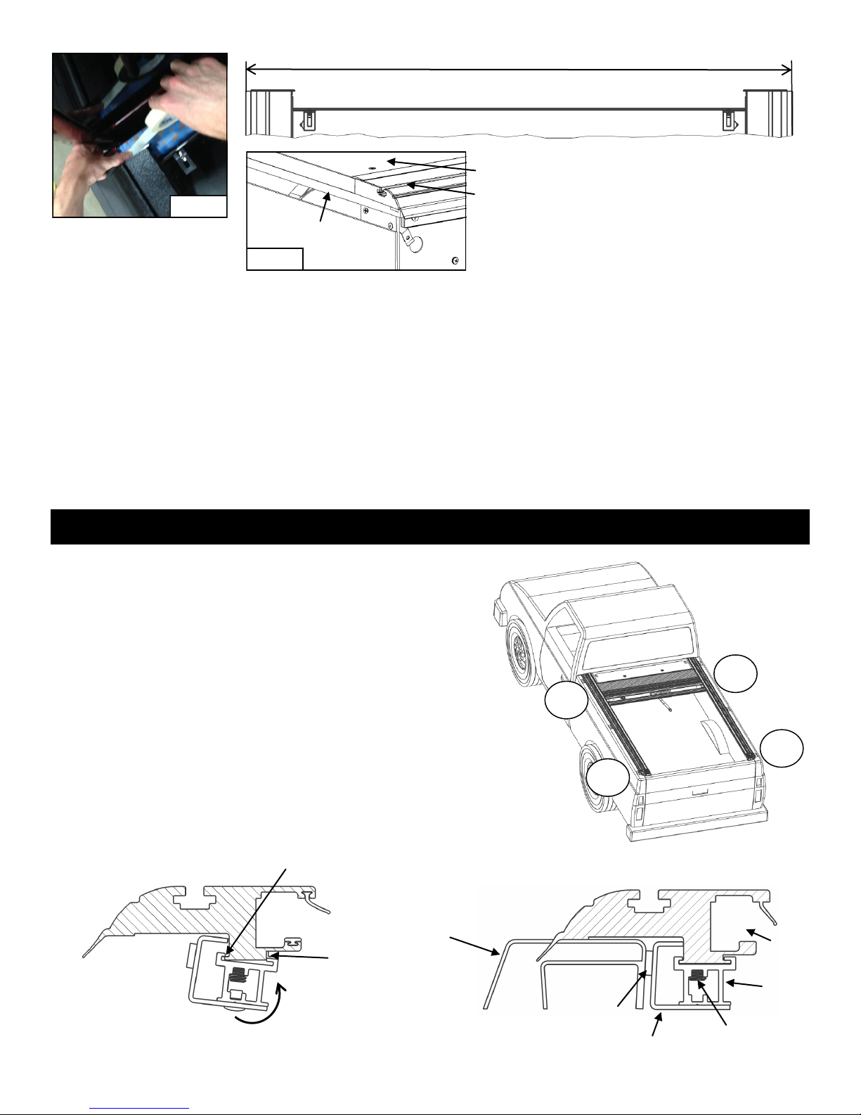
1. To open the cover, turn the actuator knob clockwise 90o until it clicks in the open position. This retracts the latches
into the handle and the cover is free to roll open into the canister. A tug on the pull strap will release the latch and
allow the cover to lock into the rails.
2. To latch the cover in one of the mid-range positions, pull it back just beyond the position desired and allow the
cover to retract until it latches into place. Latching positions are located every 12 inches along the rails. The
clicking sound is the spring-loaded latches mounted inside the handle. The latches are designed to bypass the
latching positions as the cover is being closed and to stop the cover as it is being retracted.
3. To close the cover, pull on the
strap to draw it back toward the
tailgate. When it is within easy
reach, grasp the handle by the
hand grip and pull the cover to the
latching position against the
tailgate.
OPERATING INSTRUCTIONS
ACTUATOR KNOB PULL
STRAP
FIG 13A
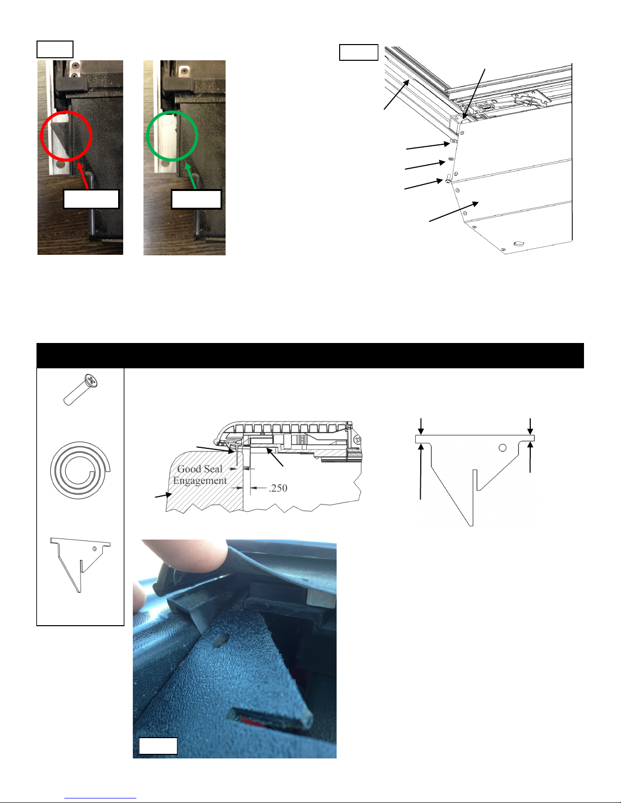
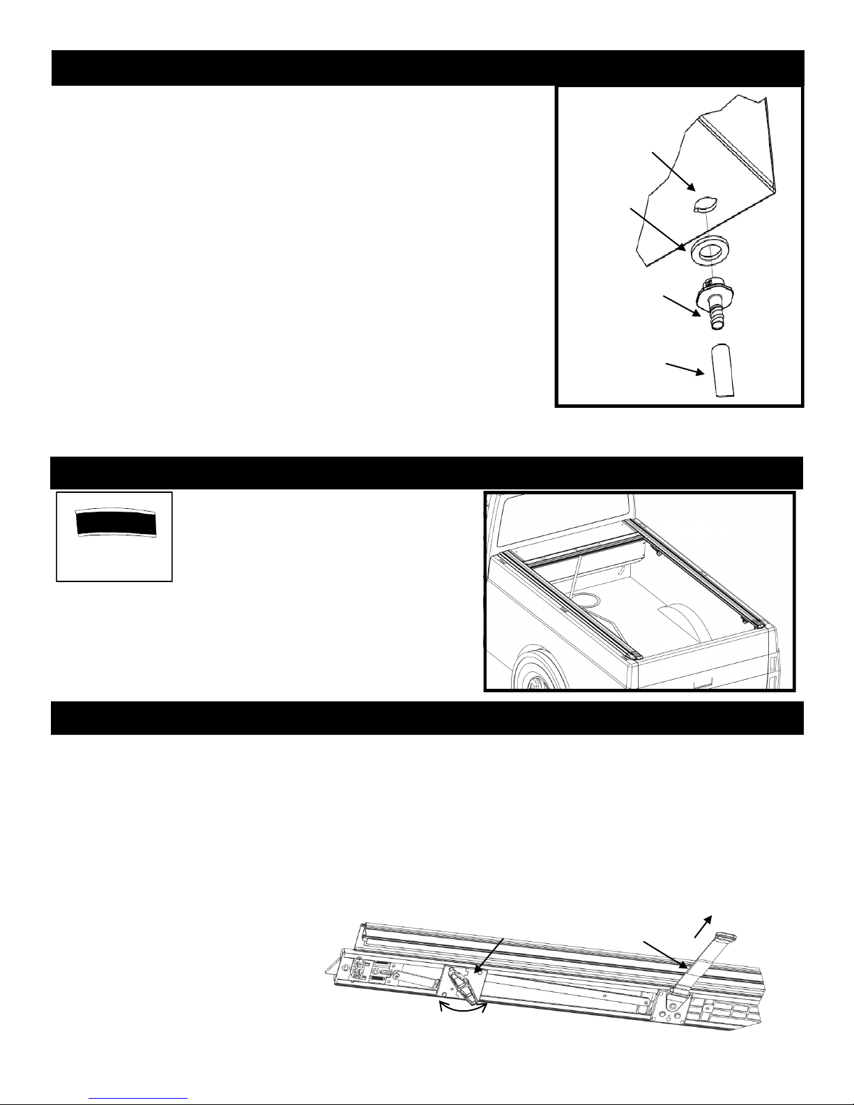
First, ensure that the Foam Washer is in place on the Drain Fitting as this
washer will help prevent water leakage. Next, test fit the drain tube to
determine the length you want to trim it. Always caution on the long side. Trim
the end that will be inserted through the truck bed using the wire cutters or a
utility knife.
With the cover opened, insert the drain tube fittings into the pre-drilled holes
on the underside of the canister by pushing them in place from under the
canister. Drain Fitting should click into place.
Place the other end of the drain tube through the plastic/rubber access port or
through the pre-drilled holes in the floor or the front wall of the truck bed. If
routing through the front wall, ensure that the drain tubes are inserted and
directed down so water flows out of the truck.
To remove the drain tubes reach under the canister, grab the drain tube fitting
and turn it while applying light downward pressure. When the retaining tabs
align with notches in the bottom of the canister the Drain Tube and Fitting will
drop out.
STEP 11: INSTALLING CANISTER DRAIN TUBES
Notch
Feature
Foam
Washer
Drain Fitting
Drain
Tube
FIG. 11A
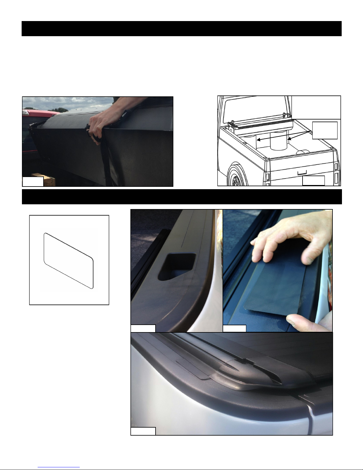
Retract the cover the fully open position.
Attach the 4” Velcro strip onto the Velcro strip
already attached to the pull strap. Pull the pull
strap over to the driver’s side rail and remove
the tape from the 4” Velcro strip. Then apply the
Velcro strip onto the underside of the rail at your
desired position. This will hold the pull strap off
of the floor and out of the way when cargo is
being stored in the truck bed.
STEP 12: ATTACH THE PULL STRAP
4” VELCRO STRIP
FIG. 12A

10
10
To help keep your Retractable Tonneau Cover looking it’s best, we
recommend washing it the same as caring for your truck finish.
However you should not wax your cover. Using a citrus-based vinyl
cleaner and protectant such as 303 brand protectant will keep your
cover looking like new.
To assure quiet, smooth operation, periodically apply a generous
amount of the same 303 brand protectant to a rag and wipe out the
inside of the rails the underside of the sweep seal and the top of the
wear strip. Repeat as needed until these components are cleaned of
debris and well lubricated.
Ensure proper placement of the sweep seal as shown in step 10. Re-apply
protectant/lubricant if the cover begins squeaking or sticking during use.
(FIG. 10A)
Alcohol, petroleum based or silicon-based cleaners such as
Armor-All® should be avoided and ARE NOT recommended for our
covers.
It is important to open and close the cover regularly; the spring that operates
the cover is self-lubricated and regular use assures that it stays in proper
working condition.
Periodically remove the Top Cover and clean out the inside of the canister.
Drain tubes may become clogged overtime and should be removed and cleaned. To remove the drain tubes reach
under the canister, grab the drain tube fitting and turn it while applying light downward pressure. When the retaining tabs
align with notches in the bottom of the canister the Drain Tube and Fitting will drop out. (FIG. 14A)
Drain Tube Fitting
Retaining Tab
Foam Washer
Canister
Drain Tube
FIG. 14A
MAINTENANCE
Rail
Cover/Fabric Panel
Wearstrip
Sweep Seal
FIG. 10A

11
On your purchase of a UltraGrooveTM by Pace Edwards. We are confident that you will get many years of trouble free
service from this accessory on your truck. Please take a moment to fill out the warranty registration form to activate
warranty coverage of your truck bed cover.
PACE EDWARDS (hereinafter referred to as the MFG.) warrants
each new Pace Edwards UltraGrooveTM retractable truck bed cover to
the original owner as follows:
FOR A PERIOD OF 3 YEARS FROM THE DATE THE UNIT IS
DELIVERED TO THE FIRST PURCHASER:
•Delamination of the Fabric Panel Assembly
•Failure of the Continuous Tension Spring
•All hardware and components
ITEMS NOT COVERED UNDER WARRANTY FOR ANY PERIOD
OF TIME:
•Rips, tears, or discoloration of the Fabric Panel material
•Seals and gaskets
•Water intrusion from any source
•Dealer and/or purchaser installed parts and accessories
CERTAIN CONDITIONS WILL VOID ALL WARRANTY.
These conditions include:
•Use for any purpose other than normal private use including
rental and promotion
•Altering the retractable truck bed cover in any manner without
written approval of the MFG
•Misuse, negligence or accident
•Installation of any part or accessory without written approval
from the MFG
•Failure to register this warranty with the MFG within fourteen
(14) days from date of delivery
CONGRATULATIONS!
CLAIMS:
If you have any warranty issues, please contact Pace Edwards Technical Support at (866) 419-4932 with the original Bill of Sale, the Unit Model and
Serial Number. After determining the validity of the warranty claim, Pace Edwards will ship a replacement part prepaid to the customer. Labor costs to
replace defective parts are the responsibility of the purchaser.
REGISTRATION:
Registering your UltraGrooveTM by Pace Edwards Retractable tonneau is an important step to ensuring you get the best possible ownership
experience. At the same time, we would like to better understand how your truck fits into your life. Feedback from Jack Rabbit XR by Pace Edwards
Retractable tonneau owners helps us design products that better fit your needs. REGISTER TODAY AT:
www.pace-edwards.com/Pace-Warranty
•Any part of a Pace Edwards UltraGrooveTM Retractable tonneau that
is found to be defective under the terms of this warranty will be
repaired or replaced using either new or reconditioned parts at the
discretion of the MFG.
•In determining what constitutes a failure under the terms of this
warranty the decision of the MFG shall be final.
•This warranty is extended to the original purchaser only and is not
transferable to subsequent purchasers.
•The MFG does not accept any responsibility in connection with the
installation of any of its products by its dealers or agents.
•The MFG does not undertake responsibility to any purchaser for
warranty express or implied by any of its dealers, distributors or
agents beyond that which is contained herein.
•Without regard to an alleged defect of its products the MFG under
any circumstances does not assume responsibility for loss of time,
inconvenience, revenue, or other consequential damage including,
but not limited to, expenses for telephone, food, lodging, travel, loss
or damage to the vehicle the products are installed on or loss or
damage to personal property of the purchaser or user of the
products.
•The MFG reserves the right to make changes in the design of,
improvements to, or warranty of its products without imposing any
obligation upon itself to provide the same for any products
theretofore manufactured.
CONDITIONS AND LIMITATIONS
This warranty is subject to certain conditions and limitations including, but
not limited to, the following:
Some jurisdictions do not allow limitations on or exclusions to warranties,
therefore some of the exclusions may not apply to you. This warranty
affords you specific legal rights. You may have other legal rights that may
vary from jurisdiction to jurisdiction.
2400 Commercial Blvd, Centralia, WA 98531 USA Thank you for choosing products by…
(360) 736-9991 (main) (360) 736-9992 (fax)
(800) 338-3697 (toll-free)
www.paceedwards.com
PACE EDWARDS PRODUCT WARRANTY
This manual suits for next models
1
Table of contents
Popular Car Spares manuals by other brands

Go Rhino
Go Rhino dominator 2 series installation instructions

ADD
ADD 2003 – Current Chevy 1500/2500 ADD Lite installation instructions

Torklift
Torklift C2207/FMTPJ07LDCHSB Important owner-operator installation instructions

Chassisworks
Chassisworks gStreet 5817-F10-12 installation guide

PPE
PPE Oil Pan installation guide

Aero-motive
Aero-motive 11107 installation instructions