EU Declaration of conformity | 1
1 EU Declaration of conformity
Manufacturer
Pacific Ventilation Pty Ltd
2/63 Wells Rd
Chelsea Heights VIC 3196
Australia
www.pacificventilation.com
hereby confirms that the following products:
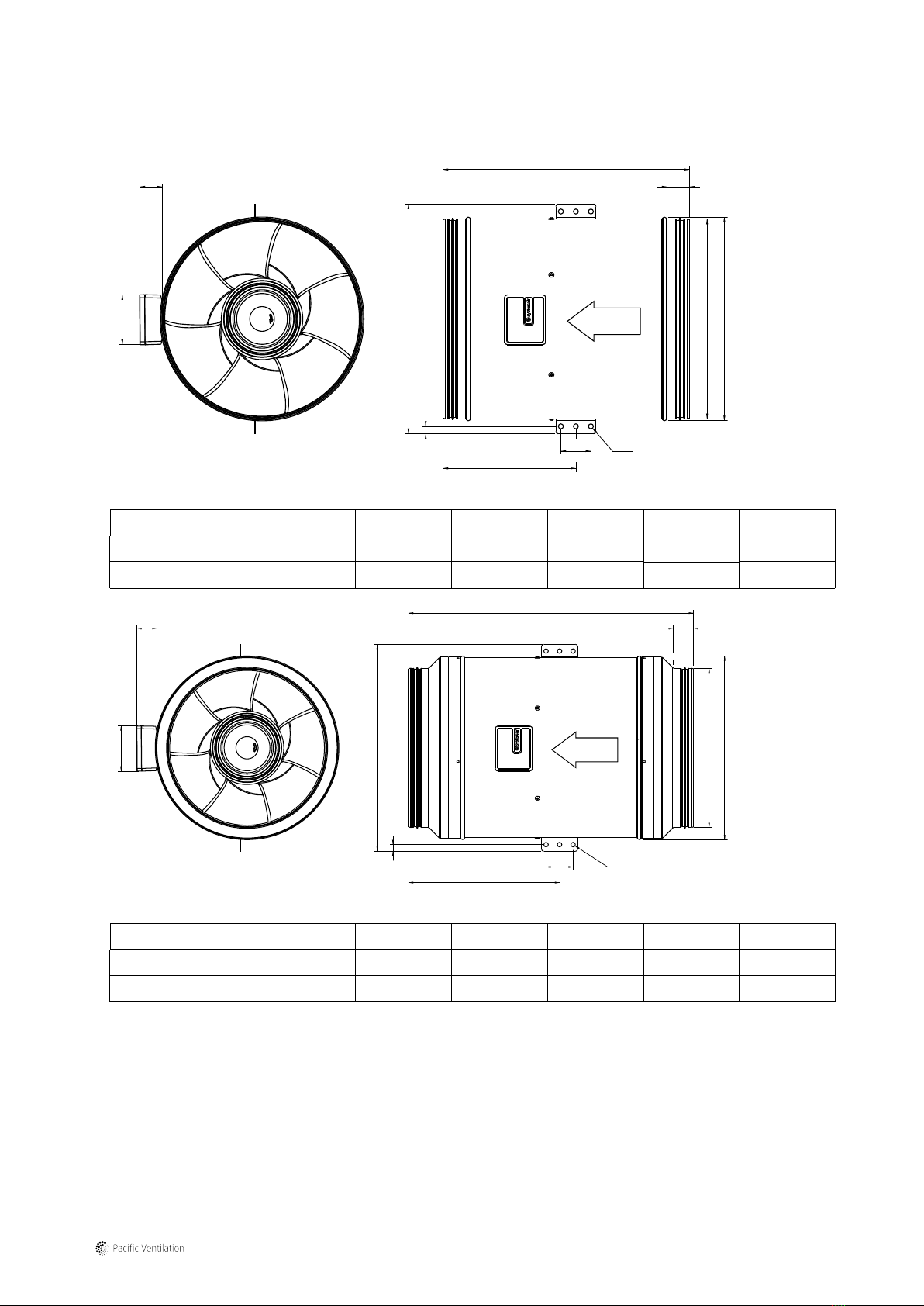
Duct fans prio 315-400 AC/EC
(The declaration applies only to product in the condition it was delivered in and installed in the facility in accordance with the included
installation instructions. The insurance does not cover components that are added or actions carried out subsequently on the
product)
Comply with all applicable requirements in the following directives and regulations
Machinery Directive 2006/42/EC Ecodesign Directive 2009/125/EC
327/2011 Requirements for fans
Low Voltage Directive 2014/35/EU
EMC Directive 2014/30/EU
The following harmonized standards are applied in applicable parts:
EN ISO 12100 Safety of machinery – General principles for design – Risk assessment and risk reduction.
EN 13857 Safety of machinery – Safety distances to prevent hazard zones being reached by upper or lower
limbs.
EN 60204-1 Safety of machinery – Electrical equipment of machines – Part 1: General requirements.
EN 60335-1 Household and similar electrical appliances – Safety Part 1: General requirements.
EN 60335-2-80 Household and similar electrical appliances – Safety – Part 2-80: Particular requirements for fans.
EN 50106 Safety of household and similar electrical appliances – Particular rules for routine tests referring to
appliances under the scope of EN 60 335-1.
EN ISO 5801 Fans – Performance testing using standardized airways.
EN 13142 Ventilation for buildings – Components/products for residential ventilation – Required and optional
performance characteristics.
EN 60529 Degrees of protection provided by enclosures (IP Code).
EN 62233 Measurement methods for electromagnetic fields of household appliances and similar apparatus
with regard to human exposure.
EN 61000-6-2 Electromagnetic compatibility (EMC) – Part 6-2: Generic standards – Immunity for industrial
environments.
EN 61000-6-3 Electromagnetic compatibility (EMC) – Part 6-3: Generic standards – Emission standards for
residential, commercial and light-industrial environments.
The complete technical documentation is available.
Skinnskatteberg, 2021-05-11
Stefan Lindberg
Technical Manager
Sofia Rask
Managing Director
269415 | A001