PairGain HLU-231 User manual

HIGAIN LINE UNIT
PAIRGAIN TECHNOLOGIES, INC.
ENGINEERING SERVICES TECHNICAL PRACTICE
150-231-108-04
Model List Number Part Number CLEI Code
HLU-231 8 150-1111-08 T1L2FY0A
R
S
2
3
2
L
MARGIN
STATUS
BRG
SPAN
XMT
RCV
BRG
SPAN
dB
HLU 231
H G LINE UNIT
IAIN
HDSL
MODE
8
D
S
X
1
SEL
PairGain

150-231-108-04, Revision 04
ii August 13, 1999 HLU-231 List 8
Revision History of This Practice
© Copyright 1999 PairGain Technologies, Inc.
PairGain andHiGain areregistered trademarks of PairGain Technologies, Inc. All other product namesmentionedin this practice
are used for identification purposes only and may be trademarks or registered trademarks of their respective companies.
Information contained in this document is company private toPairGain Technologies, Inc., and shall not be modified, used, copied,
reproduced or disclosed in whole or in part without the written consent of PairGain.
Information furnished by PairGain Technologies is believed to be accurate and reliable. However, no responsibility is assumed by
PairGain Technologies for its use; nor for any infringement of patents or other rights of third parties which may result from its use.
No license is granted by implication or otherwise under any patent or patent rights of PairGain Technologies. PairGain
Technologies reserves the right to change specifications at any time without notice.
Revision Release Date Revisions Made
01 October 3, 1997 Initial release
02 June 10, 1998 Modified alarm diagnostics, miscellaneous edits
03 April 15, 1999 New diagnostic messages added
04 August 13, 1999 Troubleshooting screens added

150-231-108-04, Revision 04 Using This Technical Practice
HLU-231 List 8 August 13, 1999 iii
USING THIS TECHNICAL PRACTICE
The following conventions are used in this manual:
•Monospace type indicates screen text, including text you type at a screen prompt.
•Keys you press are indicated by small icons such as . Key combinations to be pressed simultaneously
are indicated with a plus sign as follows: + .
•Three types of messages, identified by icons, appear in text.
For a list of abbreviations used in this document, refer to “Appendix E - Glossary” on page 65.
DOCUMENTATION
If you have comments on this PairGain document, send an email to technical_publications@pairgain.com. Type
the product name and the section number of the document in the subject area of the email message.
INSPECTING THE SHIPMENT
Upon receipt of the equipment:
•Unpack each container and inspect the contents for signs of damage. If the equipment has been damaged in
transit, immediately report the extent of damage to the transportation company and to PairGain. Order
replacement equipment, if necessary.
•Check the packing list to ensure complete and accurate shipment of each listed item. If the shipment is short
or irregular, contact PairGain as described in the Warranty located inside the back cover. If you must store
the equipment for a prolonged period, store the equipment in its original container.
Notes contain information about special circumstances.
Cautions indicate the possibility of equipment damage or personal injury.
The Electrostatic Discharge (ESD) Susceptibility symbol indicates that a device or assembly is
susceptible to damage from electrostatic discharge.
(17(5
&75/
(6&

Inspecting the Shipment 150-231-108-04, Revision 04
iv August 13, 1999 HLU-231 List 8

150-231-108-04, Revision 04 Table of Contents
HLU-231 List 8 August 13, 1999 v
TABLE OF CONTENTS
Overview ____________________________________________________________________________ 1
Features..............................................................................................................................................1
Product Enhancements ........................................................................................................1
Standard Features ................................................................................................................1
Compatibility .....................................................................................................................................2
Applications .......................................................................................................................................2
HiGain Doubler Applications..............................................................................................2
Personal Communications System Applications.................................................................3
Front Panel __________________________________________________________________________ 4
Installation___________________________________________________________________________ 8
Verification ........................................................................................................................................9
Verification without a Downstream Device........................................................................9
Verification with a Downstream Device .............................................................................9
Provisioning Requirements..............................................................................................................10
Provisioning_________________________________________________________________________ 11
Using the MODE and SEL Buttons.................................................................................................11
Setting Options through MODE and SEL.........................................................................11
Resetting to Factory Default Values..................................................................................12
Displaying System Parameter Settings..............................................................................12
Disabling an Alarm............................................................................................................12
Loopback Modes ...............................................................................................................12
Using a Maintenance Terminal........................................................................................................13
Connecting to a Maintenance Terminal.............................................................................13
Accessing the Maintenance Terminal Screens..................................................................13
Navigation Keys..................................................................................................13
Maintenance Terminal Main Menu.....................................................................14
Selecting a Maintenance Terminal Function.......................................................15
System Spans.......................................................................................................15
Using the Maintenance Terminal Screens .......................................................................................15
View Span Status Screen...................................................................................................15
Span Status Screen without Doublers .................................................................16
Span Status Screen for Doubler Applications.....................................................16
Set Clock Screen................................................................................................................19
Set Time ..............................................................................................................19
Set Date...............................................................................................................19
Update the HRU Time and Date.........................................................................19

Table of Contents 150-231-108-04, Revision 04
vi August 13, 1999 HLU-231 List 8
System Settings Screen..................................................................................................... 20
Equalization Option............................................................................................ 23
BPVT Option...................................................................................................... 23
BER Option ........................................................................................................ 24
DS0 Blocking Option ......................................................................................... 24
DS1 Line Code Option....................................................................................... 24
Margin Alarm Threshold Option........................................................................ 25
HAIS Option....................................................................................................... 25
HDSL Line Voltage Options.............................................................................. 25
Loopback Mode Screen .................................................................................................... 26
Loopback Menu without Doubler....................................................................... 27
Loopback Menu for Doubler Applications......................................................... 27
Initiating a Loopback.......................................................................................... 28
Disabling a Loopback......................................................................................... 28
View Performance Data Screen........................................................................................ 29
Performance Data Screen without Doubler........................................................ 30
Performance Data Screen for Doubler Applications.......................................... 30
View Performance History Screen.................................................................................... 31
Performance History Screen without Doubler.................................................... 31
Performance History Screen for Doubler Applications...................................... 32
View Alarm History Screen.............................................................................................. 33
Alarm History Screen without Doubler.............................................................. 34
Alarm History Screen for Doubler Applications................................................ 34
View System Inventory Screen......................................................................................... 35
System Inventory Screen without Doubler......................................................... 36
System Inventory Screen for Doubler Applications........................................... 36
View Troubleshooting Screen........................................................................................... 37
Troubleshooting _____________________________________________________________________ 40
System Alarms................................................................................................................................. 40
Alarm Option for DLC Feed............................................................................................. 41
Retiring System Alarms.................................................................................................... 41
Self Test ............................................................................................................................ 41
Loopback Operation........................................................................................................................ 42
Generic Loopback Commands.......................................................................................... 42
Special Loopback Commands........................................................................................... 44

150-231-108-04, Revision 04 Table of Contents
HLU-231 List 8 August 13, 1999 vii
Initiating a Manual Loopback Session ..............................................................................45
Setting the Loopback Time-out Option...............................................................45
Initiating a Manual Loopback Session................................................................45
Loopback Test Procedures...............................................................................................................46
General Troubleshooting Tips...........................................................................................46
GNLB Test Procedures......................................................................................................46
A1LB, A2LB, and A5LB Test Procedures........................................................................48
A3LB and A4LB Test Procedures.....................................................................................51
Appendix A - Specifications____________________________________________________________ 52
HDSL Insertion Loss Guidelines.....................................................................................................53
Power Consumption.........................................................................................................................53
Power Consumption without Doublers..............................................................................53
Power Consumption with Doublers...................................................................................54
Maximum Power Dissipation...........................................................................................................56
Maximum Current Drain..................................................................................................................56
HLU-231 List 8 Card Connector .....................................................................................................57
Network Management Control Bus...................................................................................57
Fuse Alarm ........................................................................................................................57
System Alarm Relay Output..............................................................................................58
Craft Port..........................................................................................................................................58
Appendix B - Functional Operation _____________________________________________________ 59
Timing..............................................................................................................................................59
Ground Fault Detect.........................................................................................................................60
Appendix C - Compatibility ___________________________________________________________ 61
T1 Repeater Shelves and Related Equipment..................................................................................61
HiGain Doubler Circuit Deployment...............................................................................................61
Appendix D - Product Support _________________________________________________________ 63
Technical Support............................................................................................................................63
World Wide Web.............................................................................................................................63
Returns.............................................................................................................................................63
Appendix E - Glossary ________________________________________________________________ 65
Certification and Warranty_______________________________________________ Inside Back Cover

List of Figures 150-231-108-04, Revision 04
viii August 13, 1999 HLU-231 List 8
LIST OF FIGURES
1. HLU-231 List 8 Front Panel........................................................................................................................... 4
2. Installing the HLU-231 List 8 into a Shelf ..................................................................................................... 8
3. Maintenance Terminal Main Menu .............................................................................................................. 14
4. System Spans................................................................................................................................................ 15
5. Span Status Screen: No Doubler................................................................................................................... 16
6. Span Status Screen: Four Doublers (Span 5)................................................................................................ 16
7. Set Clock Screen........................................................................................................................................... 19
8. System Settings Screen................................................................................................................................. 20
9. Loopback Menu: No Doubler....................................................................................................................... 27
10. Loopback Menu: Four Doublers................................................................................................................... 27
11. NLOC Loopback Mode Reported in the Maintenance Terminal Main Menu.............................................. 28
12. Performance Data Screen: No Doubler......................................................................................................... 30
13. Performance Data Screen: Four Doublers (Span 5)...................................................................................... 30
14. 31-Day Performance History Screen: No Doubler....................................................................................... 31
15. 31-Day Performance History Screen: Four Doublers (Span 5).................................................................... 32
16. Alarm History Screen: No Doubler.............................................................................................................. 34
17. Alarm History Screen: Four Doublers (Span 5) ........................................................................................... 34
18. System Inventory Screen: No Doubler......................................................................................................... 36
19. System Inventory Screen: Four Doublers..................................................................................................... 36
20. Troubleshooting Screen for a Doubler Application...................................................................................... 37
21. Troubleshooting Screen Describing Circuit Problem................................................................................... 37
22. Troubleshooting with Help........................................................................................................................... 38
23. Troubleshooting with Margin Values........................................................................................................... 39
24. Troubleshooting with Insertion Loss Values................................................................................................ 39
25. Loopback Summary...................................................................................................................................... 42
26. Loopback Configurations ............................................................................................................................. 47
27. HLU-231 List 8 Card-edge Connector ......................................................................................................... 57
28. RS-232 Craft Port Pinouts ............................................................................................................................ 58
29. HLU-231 List 8 Block Diagram................................................................................................................... 59

150-231-108-04, Revision 04 List of Tables
HLU-231 List 8 August 13, 1999 ix
LIST OF TABLES
1.Front-panel Description....................................................................................................................................5
2.Front-panel Display Messages .........................................................................................................................6
3.Navigational Keys on the Maintenance Terminal..........................................................................................13
4.Maintenance Terminal Screens ......................................................................................................................14
5.Span Status Fields and Descriptions...............................................................................................................17
6.HDSL System Alarms....................................................................................................................................18
7.Loopback Messages........................................................................................................................................18
8.HLU-231 List 8 System Settings....................................................................................................................21
9.Loopback Field Messages and Descriptions ..................................................................................................26
10.Errored and Unavailable Seconds Definitions ...............................................................................................29
11.Alarm History Fields and Descriptions..........................................................................................................33
12.HDSL System Alarms....................................................................................................................................40
13.Summary of HiGain Loopback Codes ...........................................................................................................43
14.Addressable Repeater Loopback Commands (A1LB, A2LB, A5LB)...........................................................48
15.Addressable Repeater Loopback Commands (A3LB and A4LB) .................................................................51
16.HDSL Loss Over Cables................................................................................................................................53
17.HLU-231 Power Parameters—No Doubler....................................................................................................53
18. HLU-231 Power Parameters—Single Doubler (HDU-451 List 1 or 2)........................................................54
19.HLU-231 Power Parameters—Single Doubler (HDU-439 or HDU-437 Lists 1 and 1B).............................54
20.HLU-231 Power Parameters—Single Doubler (HDU-409 List 2) ................................................................54
21.HLU-231 Power Parameters—Two Doublers (HDU-451 List 3, 4, 3B or 4B).............................................55
22.HLU-231 Power Parameters—Two Doublers (HDU-439 or HDU-437 Lists 1 and 1B) ..............................55
23.HLU-231 Power Parameters—Two Doublers (HDU-409 List 2)..................................................................55
24.HLU-231 Power Parameters—Three and Four Doublers (HDU-409 List 2) ................................................55
25.HiGain Doubler Deployment Matrix..............................................................................................................62

List of Tables 150-231-108-04, Revision 04
x August 13, 1999 HLU-231 List 8

150-231-108-04, Revision 04 Overview
HLU-231 List 8 August 13, 1999 1
OVERVIEW
The PairGain®HiGain®Line Unit HLU-231 List 8 is the Central Office (CO) side of a repeaterless
T1 transmission system. When used in conjunction with a HiGain Remote Unit (HRU), the system provides
1.544 Mbps transmission on two unconditioned copper pairs over the full Carrier Service Area (CSA) range. The
CSA includes loops up to 12,000 feet of24 AWG or 9,000 feet of 26 AWG wire, including bridged taps. This line
unit can be used with HiGain Doubler Units (HDUs) to extend reach.
FEATURES
Product Enhancements
•Five-span range with four doublers (60 kft, 24 AWG)
•Four line-powered spans (three doublers and one remote)
•Reduced power consumption
•Ultra-low wander (Stratum 1 compliant)
•Low line-power option (-140 Vdc) for circuits with a single doubler
•Selectable Power Feed (PWRF) modes: Auto, High and Low
•Grounded loop detection on High-bit-rate Digital Subscriber Line (HDSL)
•Bipolar Violation Transparency (BPVT) options
•Bit Error Rate (BER) alarm options
•HRU loopback screen
•Inventory and troubleshooting screens
•Loss of Signal/Alarm Indicator Signal (LOS/AIS) payload alarm option
•Remote Loss of Signal (RLOS) disable alarm option
•Supports HRU-411 in PCS applications
•Default setting screen option
•Payload (PL) or HiGain (HG) loopback source identification
Standard Features
•Selectable DS1 pre-equalizer
•Front-panel features:
–Four-character status display
–DS1 splitting and bridge access
–Status LED
–RS-232 craft port for connection to a maintenance terminal
•Compatible with SXSS shelves, and equivalent
•Selectable loopback activation codes
•Network Management and Administration (NMA) interface

Overview 150-231-108-04, Revision 04
2 August 13, 1999 HLU-231 List 8
•Lightning and power cross protection on HDSL interfaces
•Full duplex 2B1Q HDSL transmission on two pairs at 784 kbps
•Margin threshold alarm
COMPATIBILITY
The HLU-231 List 8 is designed to mount in 220 mechanics shelves. For a list of compatible shelves, see
“Appendix C - Compatibility” on page 61.
All generations of HiGain HLU and HRU modules are compatible with each other. To take advantage of the
enhanced features of newer HiGain doublers, refer to “HiGain Doubler Circuit Deployment” on page 61.
APPLICATIONS
HiGain systems provide a cost-effective, easy-to-deploy method for delivering T1 High Capacity Digital Service
(HCDS) over metallic pairs.
•The service is deployed over two unconditioned, non-loaded copper pairs, yet it demonstrates a quality that
is competitive with fiber optics.
•Conventional, in-line, T1 repeaters are not required.
•Cable pair conditioning, pair separation and bridged tap removal are not required.
In general, HiGain systems:
•Operate with any number of other T1, POTS, Digital Data Service (DDS) or other HiGain systems sharing
the same cable binder group
•Can be used with customers requiring DS1 service on a temporary or permanent basis
•Provide a means of quickly deploying service in advance of fiber-optic transmission systems.
With a HiGain system, service can be provided within hours. Fiber-optic systems can be installed incrementally
and cut-over from the installed HiGain system when convenient to do so.
HiGain Doubler Applications
For applications without doublers, the HLU-231 is directly connected to the HRU by the two HDSL cable pairs.
The HLU-231 List 8 is compatible with all HiGain HRUs.
For doubler applications, one to four doublers may be used in the HDSL loops between the HLU and HRU.
•If the HRU is line-powered, the HLU-231 List 8 can power three doublers and the remote unit (HRU-402 or
HRU-411) for a total of four spans.
•If the HRU is locally powered, the HLU can power up to four doublers for a total of five spans.
These extended ranges are only available when using the HDU-409, HDU-404 or HDU-407
micro-doublers with the HRU-411 or HRU-402. Older doublers (HDU-451, HDU-439 and HDU-437)
cannot be used in circuits with more than two doublers in any line or local power system. For
compatibility guidelines on mixing newer doublers with older HRU and HLU models, refer to
“HiGain Doubler Circuit Deployment” on page 61.
For additional information about associated HiGain equipment, refer to the respective HiGain
technical practice (see “Appendix D - Product Support” on page 63).

150-231-108-04, Revision 04 Overview
HLU-231 List 8 August 13, 1999 3
Personal Communications System Applications
The HLU-231 List 8 is required for Personal Communications System (PCS) applications that use the
HRU-411. The HRU-411 has an onboard 130 Vdc, 8.5 W power supply that can power the 200 mW PCS remote
radio ports. The line unit recognizes the HRU-411 (if CPE POWER switch is set to ON) and performs the
following two functions required by the HRU-411 to bring up the NEC radio port:
•Increases the HDSL line voltage to its high ±112 Vdc level with the PWRF option set to AUTO
•Enables HRU-411 to turn on its 130 Vdc radio port supply

Front Panel 150-231-108-04, Revision 04
4 August 13, 1999 HLU-231 List 8
FRONT PANEL
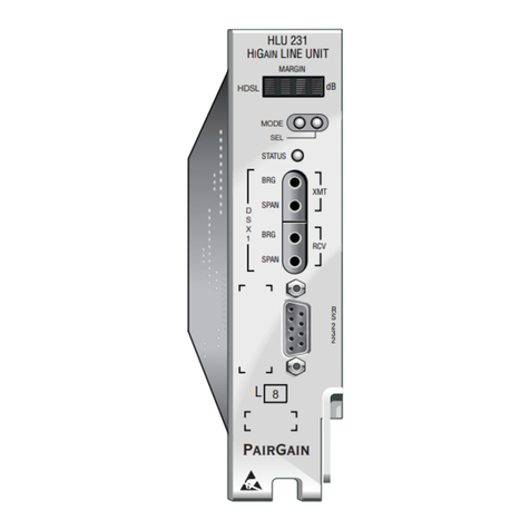
The HLU-231 List 8 front panel is shown in Figure 1. The front-panel components are described in Table 1. For
pinout diagrams of the HLU card-edge connector and the craft port, refer to “Appendix A - Specifications” on
page 52.
Figure 1. HLU-231 List 8 Front Panel

150-231-108-04, Revision 04 Front Panel
HLU-231 List 8 August 13, 1999 5
Table 1. Front-panel Description
Front-panel Feature Function
Front-panel display Displays four-character status, provisioning, and alarm system messages.The front-panel display
illuminates when power is initially applied. To conserve power the display only remains on for
4 minutes. Using the MODE or SEL buttons reactivates the display and restarts the 4-minute timer.
Refer to Table 2 on page 6 for a listing of the four-character messages.
System option buttons
(MODE and SEL)
Permits the user options to be monitored and modified without the need of a maintenance terminal.
Used to initiate all HiGain loopbacks and to display DSX-1 line parameters and line unit identity.
Status LED The status LED can report the following conditions:
Green Normal operation
Flashing green HDSL acquisition
Red Fuse Alarm
Flashing red System alarm
Yellow Self Test is in process or an HLU-231 List 8 Customer Remote Loopback (CREM) or a Network
Local Loopback (NLOC) is in effect.
Flashing yellow HLU-231 List 8 is Armed to respond to Intelligent Repeater Loop (ILR) codes.
DSX-1 access jacks
SPAN Provides splitting jack access to (XMT) and from (RCV), the HDSL span at the DSX-1 interface.
Breaks the XMT and RCV paths to permit test signal insertion and retrieval.
BRG Provides non-intrusive bridging jack access to (XMT) and from (RCV) the HDSL span at the DSX-1
interface. Allows the two T1 payloads to be monitored.
Craft (RS-232) port Provides bidirectional communication between the unit and an external terminal to allow
configuration and performance monitoring through the Maintenance Terminal screens.
CLEI and ECI bar code label Provides the human-readable Common Language Equipment Identifier (CLEI) code number and the
Equipment Catalog Item (ECI) bar code number.
List number Identifies the version of the HLU-231.
Retaining latch Retains the card in the shelf when pulled up and extracts the card from the shelf when pulled down.
Configuration number Contains either a five or six-digit warranty configuration number or a stand-alone two or three-digit
configuration number as follows:
Digit 1 - Last digit of shipment year
Digits 2 and 3 - Shipment month
Digits 4, 5, and 6 - Configuration number
The configuration number can also be found on a small bar label that contains the Julian date code
and part number. This gummed label may be affixed to the PC board or to the front panel.

Front Panel 150-231-108-04, Revision 04
6 August 13, 1999 HLU-231 List 8
Table 2 lists the front-panel display messages. The four-character displays reports the code of a pertinent alarm,
loopbackor diagnostic message, insome cases followedby a second four-character messagethat modifiesthe first
message with a value or current configuration setting.
Table 2. Front-panel Display Messages
Message Full Name Description
ALARM MESSAGES
ACO Alarm CutOff A system alarm has occurred, and has been retired to an ACO
condition by pressing the SEL button on the HLU front panel.
ALRM Alarm Condition A system alarm condition is in effect.
BER Bit Error Rate A system BER alarm is in effect.
LLOS Local Loss of Signal Indicates that no signal is detected at the T1 input to the HLU.
Causes a system alarm.
LOSW Loss of Sync Word Indicates that one of the HDSL loops has lost sync. Causes a system
alarm.
MAL1 or MAL2 Margin Alarm Loop 1 or Loop 2 The margin on HDSL Loop 1 or Loop 2 has dropped below the
threshold (1 to 15 dB) as set by the operator.
RLOS Remote Loss of Signal Indicates that no signal is detected at the DS1 input to the HRU.
Causes a system alarm.
LOOPBACK MESSAGES
CDUn?Customer Doubler nLoopback Query to initiate loopback at doubler n to CI, where nis the number
of the doubler.
CLOC Customer Local Loopback Signal from customer is looped back to the customer at the HRU.
CREM Customer Remote Loopback Signal from customer is looped back to the customer at HLU-231.
NDUn?Network Doubler nLoopback Query to initiate loopback at doubler n to network, where nis the
number of the doubler.
NLOC Network Local Loopback DSX-1 signal is looped back to DSX-1 at HLU.
NREM Network Remote Loopback DSX-1 signal is looped back to DSX-1 at the HRU.
SMJK Remote SmartJack Loopback Signal from DSX-1 is looped back at the HRU by the HRU SmartJack
module.
DIAGNOSTIC MESSAGES
1=xx or 2=yy HDSL Loop Margins Indicates the power of the received HDSL signal on each loop
relative to noise. Any value of ‘06’ or greater is adequate for reliable
system operation.
ACQ1 or ACQ2 Acquisition 1 or 2 The multiplexers of the HLU and the HRU or first doubler are trying
to establish synchronization over Loops 1 or 2 of Span 1.
AnL1 or AnL2 Acquisition nLoop 1 or Loop 2 The multiplexers of the two devices on Span nare trying to establish
synchronization with each other on Loops 1 or 2, where nis the
number of the span.
ARM HiGain System Armed Armed to respond to Intelligent Repeater Loop Codes.
BAD RT? No response from HRU The HLU does not receive any response from the HRU. Thus, the
integrity of the HRU or the two HDSL loops (they may be open) is
questionable.
CODE xxxx Line Code: AMI, B8ZS, AUTO The line code that HLU-231 List 8 is receiving at its DSX-1 interface,
if the DS1 option is set to Auto. Otherwise, it mimics either of the
other two DS1 line code settings, Alternate Mark Inversion (AMI) or
Bipolar with 8-zero Substitution (B8ZS). Displayed during System
Settings review mode.

150-231-108-04, Revision 04 Front Panel
HLU-231 List 8 August 13, 1999 7
DS0 DS0 Blocked Channels Indicates status of DS0 blocked channels. NONE indicates no
channels are blocked. BLK indicates some channels are blocked.
FERR Framing Bit Error Framing bit error occurred at HLU T1 input.
FRM xxxx Frame: SF, ESF, UNFR, NONE Defines the type of frame pattern being received from the DSX-1:
SuperFrame (SF), Extended SuperFrame (ESF), Unframed (UNFR),
or NONE. Displayed during System Settings review mode.
H1ES or H2ES HDSL CRC Error Channel 1 or
Channel 2
HDSL Loop 1 or Loop 2 CRC error.
nHDU Number of Doublers This message indicates the number (n) of doublers in the circuit.
INSL, then xxDB Maximum Insertion Loss The maximum Insertion Loss message (INSL) appears followed by
xxDB, where xx is the maximum insertion in dB of all spans and
loops.
LBPV Local Bipolar Violation A bipolar violation has been received at the T1 input to the HLU-231.
LIST xxxx HLU-231 List Number The software list number (xxxx) appears during the System Settings
review mode. Press the MODE button for 3 seconds to display the
list number.
MNGD Managed The HLU is under control of the HMU-319 network management
unit. In this state, the front-panel craft port and pushbuttons are
disabled.
PWRF GND Power Feed Ground One of the HDSL loops has been grounded.
PWRF ON Power Feed On Indicates that the HDSL loops are not grounded or shorted.
PWRF OFF Power Feed Off HDSL span power has been turned off by setting the PWFD option
to DIS, or HDSL span power has been turned off by use of the
A1LB/A2LB/A5LB Intelligent Office Repeater (IOR) Power Down
code.
PWRF SHRT Power Feed Short Indicates a short between the two HDSL pairs. This same message
can occur with an HRU that is drawing the correct amount of power
over good cable pairs but cannot communicate with the HLU.
SELF TEST Self Test The HLU is in a self-test mode. This occurs every power On/Off
cycle.
SIG1 or SIG2 Signal 1 or Signal 2 The transceivers of the HLU and HRU or first doubler are trying to
establish contact with each other on Loop 1 or Loop 2 of Span 1.
SnL1 or SnL2 Signal nLoop 1 or Loop 2 The transceivers of the two devices on Span nare trying to establish
contact with each other on Loop 1 or Loop 2, where nis the number
of the span.
TLOS Transmit Loss of Signal DSX-1 signal is looped back to the DSX-1 interface at the HRU. HRU
is in a logic loopback state caused by a loss of its DS1 input from
the CI, if enabled at the HRU by its TLOS switch option.
VER xxxx HLU-231 Version Number The software version number (xxxx) appears during the System
Settings review mode. Press the MODE button for 3 seconds to
display the software version.
Table 2. Front-panel Display Messages (Cont.)
Message Full Name Description

Installation 150-231-108-04, Revision 04
8 August 13, 1999 HLU-231 List 8
INSTALLATION
Figure 2. Installing the HLU-231 List 8 into a Shelf
1Slide the HLU-231 into the card guides of the desired slot, then push the unit back until it touches the
backplane card-edge connector and the retaining latch on the front panel opens (Figure 2).
2Place your thumbs on the HLU-231 front panel and push the HLU-231 into the card-edge connector until the
retaining latch closes. This indicates that the card is properly seated.
Upon receipt of the equipment, visually inspect the contents for signs of damage. If the
equipment has been damaged in transit, immediately report the extent of damage to the
transportation company and to PairGain Technologies.
When installing an HLU in a chassis, be sure to wear an antistatic wrist strap. Avoid touching
components on the circuit board.

150-231-108-04, Revision 04 Installation
HLU-231 List 8 August 13, 1999 9
VERIFICATION
Once the HLU-231 is installed, verify that it is operating properly. To do this, you need to monitor the following:
•Status LED
•Status messages reported by the front-panel display (see Table 2 on page 6)
Verification without a Downstream Device
If there is no downstream device installed:
1Verify that the HLU powers up. (The front-panel display illuminates and reports four-character status
messages. See Table 2 on page 6 for a list of messages.)
2Verify that the HLU attempts to communicate with downstream devices. Even if a downstream device is not
present, the following events should occur:
aThe front-panel display reports four-character status messages.
bThe HLU enters self-test mode (Status LED is yellow).
cThe HLU again attempts communication with downstream devices, repeating events athrough buntil a
downstream device is detected.
Verification with a Downstream Device
If a downstream device has been installed:
1Verify the HLU powers up. (The front-panel display illuminates and reports status messages.)
2Verify the HLU attempts to communicate with downstream devices (status LED flashes green). One of the
following occurs:
•If downstream devices are successfully identified and the HDSL loops synchronize, the HLU status LED
will be a steady green. The HLU reports normal margin messages on the front-panel display.
•If downstream devices are not successfully identified, the HLU reports four-character status messages
and enters self-test mode. The HLU successively:
aenters self-test mode
bcompletes self-test mode
cattempts communication again
dreports four-character status messages.
The HLU repeats this cycle until a downstream device is detected.
3If there is more than one span, verify that each subsequent span synchronizes normally by monitoring the
front-panel display messages.
4If a remote unit is installed, verify that the last span synchronizes normally. The HLU status LED should be
a steady green, and the front-panel display reports normal margin messages.
5Verify that a valid T1 signal has been applied to the HLU and the HRU.
•If no T1 signal is being applied to either the HLU or the HRU inputs, then the appropriate T1 alarms
(LLOS or RLOS) are observed on the front-panel display and the status LED flashes red.
•If a valid T1 signal is being supplied to the HLU and HRU, then T1 alarm indications should be absent
and the status LED should be a steady green.

Installation 150-231-108-04, Revision 04
10 August 13, 1999 HLU-231 List 8
PROVISIONING REQUIREMENTS
Refer to “Provisioning” on page 11 for information about using the MODE and SEL buttons or the Maintenance
Terminal screens to configure the HLU. While the MODE and SEL buttons can be used to manually accomplish
some provisioning tasks, such as setting system options, the Maintenance Terminal screens (available when you
connect a PC to the craft port) can handle all provisioning tasks. Tasks that you need to complete are:
1Set the time and date (see “Set Clock Screen” on page 19).
2Set the circuit IDs (see “View System Inventory Screen” on page 35).
Assuming that the HLU has been successfully installed and provisioned, youshould do the followingto ensure an
accurate Alarm History and Performance History.
1Clear the Span Status, Performance Data, and Performance History screens. This can be accomplished by
pressing (clear) at the Span Status screen (see “View Span Status Screen” on page 15).
2Clear the Alarm History screens (see “View Alarm History Screen” on page 33).
&
Other manuals for HLU-231
8
This manual suits for next models
1
Table of contents
Other PairGain Switch manuals
Popular Switch manuals by other brands

schmersal
schmersal AZ 200 T operating instructions

AETEK
AETEK H60-044-30-150 Quick installation guide

Aruba
Aruba Instant On 1430 Installation and getting started guide

Razer
Razer Base Station Chroma Master guide

ATEN
ATEN Master View CS-1762 user manual

Magnetrol
Magnetrol TD1 Series Installation and operating manual