General Safety Information
Some dust created
by power sanding,
sawing, grinding, drilling and other con-
struction activities contains chemicals
known to cause cancer, birth defects or
other reproductive harm.
Some examples of these chemicals are:
1. Lead from lead-based paints.
2. Crystalline silica from bricks and
cement and other masonry products.
3. Arsenic and chromium from
chemically-treated lumber.
Your risk from these exposures vary,
depending on how often you do this
type of work. To reduce your exposure
to these chemicals: work in a well venti-
lated area and work with approved
safety equipment. Always wear
OSHA/NIOSH approved, properly fitting
face mask or respirator when using such
tools.
Always follow prop-
er operating proce-
dures as defined in this manual even if
you are familiar with use of this or simi-
lar tools. Remember that being careless
for even a fraction of a second can
result in severe personal injury.
BE PREPARED FOR JOB
1. Wear proper apparel. Do not wear
loose clothing, gloves, neckties, rings,
bracelets or other jewelry which may
get caught in moving parts of machine.
2. Wear protective hair covering to
contain long hair.
3. Wear safety shoes with non-slip soles.
4. Wear safety glasses complying with
United States ANSI Z87.1. Everyday
glasses have only impact resistant
lenses. They are NOT safety glasses.
5. Wear face mask or dust mask if oper-
ation is dusty.
6. Be alert and think clearly. Never oper-
ate power tools when tired, intoxicat-
ed or when taking medications that
cause drowsiness.
PREPARE WORK AREA FOR JOB
1. Keep work area clean. Cluttered work
areas invite accidents.
2. Do not use power tools in dangerous
environments. Do not use power
tools in damp or wet locations. Do
not expose power tools to rain.
3. Work area should be properly lighted.
4. Proper electrical receptacle should be
available for tool. Three-prong plug
should be plugged directly into
properly grounded, three-prong
receptacle.
5. Extension cords should have a
grounding prong and the three wires
of the extension cord should be of
the correct gauge.
6. Keep visitors at a safe distance from
work area.
7. Keep children out of workplace.
Make workshop childproof. Use pad-
locks or master switches to prevent
any unintentional use of power tools.
TOOL SHOULD BE MAINTAINED
1. Always unplug tool prior to inspection.
2. Consult manual for specific maintain-
ing and adjusting procedures.
3. Keep tool lubricated and clean for
safest operation.
4. Remove adjusting tools. Form habit
of checking to see that adjusting
tools are removed before switching
machine on.
5. Keep all parts in working order.
Check to determine that the guard or
other parts will operate properly and
perform their intended function.
6. Check for damaged parts. Check for
alignment of moving parts, binding,
breakage, and mounting or any other
condition that may affect a tool’s
operation.
7. A guard or other damaged part
should be properly repaired or
replaced. Do not perform makeshift
repairs. (Use parts list provided to
order replacement parts.)
KNOW HOW TO USE TOOL
1. Use right tool for job. Do not force
tool or attachment to do a job for
which it was not designed.
2. Disconnect tool when changing drill
bit or cutter.
3. Avoid accidental start-up. Make sure
that the tool is in the OFF position
before plugging in.
4. Do not force a tool. It will work
most efficiently at the rate for which
it was designed.
5. Keep hands away from moving parts
and cutting surfaces.
6. Never leave tool running unattend-
ed. Turn the power off and do not
leave tool until it comes to a com-
plete stop.
7. Do not overreach. Keep proper foot-
ing and balance.
8. Never stand on tool. Serious injury
could occur if tool is tipped or if drill
bit is unintentionally contacted.
9. Know your tool. Learn the tool’s
operation, application and specific
limitations.
10. Use recommended accessories (refer
to page 13). Use of improper acces-
sories may cause risk of injury to
persons.
11. Handle workpiece correctly. Protect
hands from possible injury.
2
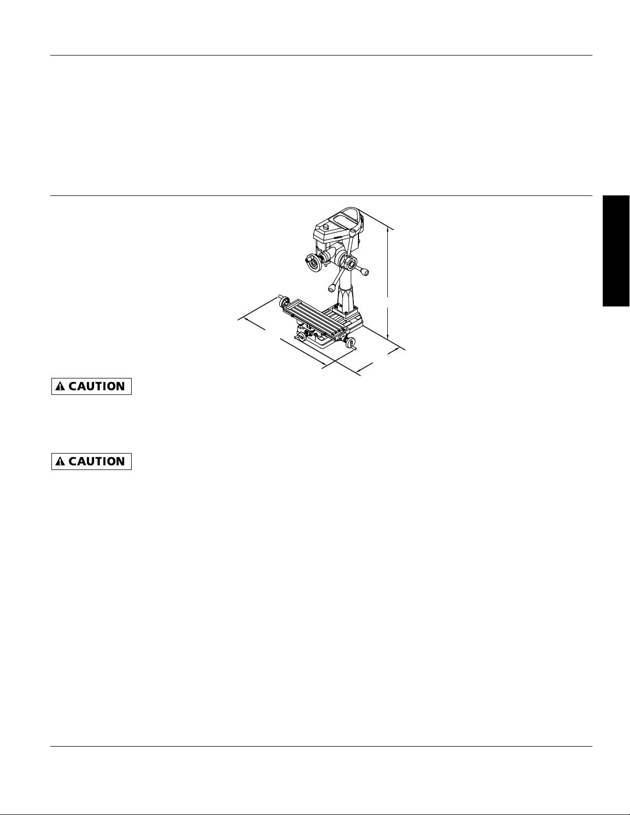
Palmgren Operating Instructions and Parts Manual
Palmgren Mill Drill
80161A
E
N
G
L
I
S
H