Palmgren 80161 User manual

ooppeerraattiinnggmmaannuuaall&&ppaarrttsslliisstt8800116611&&7700110044
MMIILLLLDDRRIILLLLAANNDDSSTTAANNDD
Read carefully and follow all safety rules and operating instructions before
first use of this product.
20953.09-0503

DDEESSCCRRIIPPTTIIOONN
Palmgren 12-Speed Mill Drill Model 80161 is a ruggedly construct-
ed machine providing accurate milling, drilling and boring capabil-
ities.The fully enclosed R-8 spindle has heavy-duty tapered thrust
bearings at top and bottom of quill, adjustable depth of stop with
scale, fine feed adjustment handwheel with .001” graduations and
quill lock down handle for securely clamping spindle at desired
depth. One piece cast iron head rotates 360° and travels vertically
by rack and pinion.
Hinged pulley cover allows fast and easy speed changes. Large
317/8x 93/8” table has dovetail ways with adjustable gibs and bronze
lead screw nuts for accurate and rigid table positioning.Table has
four 5/8” T-slots, zero setting handwheel dials with .001” gradua-
tions, adjustable stops for longitudinal feed and cross feed way
cover.
A 1½ HP, 1725 RPM, 115/230 volt single-phase motor is included.
Palmgren Mill Drill Stand Model 70104 is a heavy-duty stand for
mounting the Palmgren mill drill and many other mill drills. Stand
is 14 gauge steel providing strength and rigidity. Stand features
mounting flanges for mounting stand to floor, large chip pan,
mounting bolts and leveling pads.
UUNNPPAACCKKIINNGG
Refer to Figure 1.
Check for shipping damage. If damage has occurred, a claim must
be filed with carrier immediately. Check for completeness.
Immediately report missing parts to dealer.
Carefully open crate and remove loose parts box. Unbolt mill drill
from shipping pallet and remove from crate using heavy duty lift-
ing equipment such as an overhead crane.
WARNING: Be careful not to touch overhead power lines, piping,
lighting, etc. if lifting equipment is used. Mill Drill weighs approxi-
mately 650 lbs. Proper tools, equipment and qualified personnel
should be employed in all phases of unpacking and installation.
Mill drill is shipped assembled except for certain parts shipped
loose in a wooden box. Locate and account for the following parts:
A Drill chuck arbor
B 5/8” Drill chuck with key
C Face mill arbor
D 3” Face milling cutter
E Two Table handwheels
F R8/3MT Adapter
G Drawbar
Optional stand is shipped unassembled.
IMPORTANT: Table is coated with a protectant. To ensure proper fit
and operation, remove coating. Coating is easily removed with
mild solvents, such as mineral spirits, and a soft cloth. Avoid getting
cleaning solution on paint or any of the rubber or plastic parts.
Solvents may deteriorate theses finishes. Use soap and water on
paint, plastic or rubber components. After cleaning, cover all
exposed surfaces with a light coating of oil. Paste wax is recom-
mended for table tops.
WARNING: Never use highly volatile solvents. Non-flammable sol-
vents are recommended to avoid possible fire hazard.
SPECIFICATIONS
Model 80161
Horsepower . . . . . . . . . . . . . . . . . . . . . . . . . . . . . . . . . . . . . . . . . . . . . . . .11/2HP
12 Speeds 120, 190, 230, 285, 370, 440, 770, 1040, 1220, 1450,
1800, 2500 RPM
Table size . . . . . . . . . . . . . . . . . . . . . . . . . . . . . . . . . . . . . . . . . . . . . .317/8x 93/8”
T-slots . . . . . . . . . . . . . . . . . . . . . . . . . . . . . . . . . . . . . . . . . . . . . . .5/8” slots, four
Swing . . . . . . . . . . . . . . . . . . . . . . . . . . . . . . . . . . . . . . . . . . . . . . . . . . . . . . . . .16”
Spindle taper . . . . . . . . . . . . . . . . . . . . . . . . . . . . .R-8 with 7/16”-20 drawbar
Drilling capacity . . . . . . . . . . . . . . . . . . . . . . . . . . . . . . . . . . . .11/4” mild steel
11/2” cast iron
End mill capacity . . . . . . . . . . . . . . . . . . . . . . . . . . . . . . . . . . . . .3/4” mild steel
Face mill capacity . . . . . . . . . . . . . . . . . . . . . . . . . . . . . . . . . . . .3” mild steel
Spindle stroke . . . . . . . . . . . . . . . . . . . . . . . . . . . . . . . . . . . . . . . . . . . . . . . . . .5”
Max. distance spindle to table . . . . . . . . . . . . . . . . . . . . . . . . . . . . . . . .173/4”
Head swivel . . . . . . . . . . . . . . . . . . . . . . . . . . . . . . . . . . . . . . . . . . . . . . . . . .360°
Quill diameter . . . . . . . . . . . . . . . . . . . . . . . . . . . . . . . . . . . . . . . . . . . . . . . . . .3”
Column diameter . . . . . . . . . . . . . . . . . . . . . . . . . . . . . . . . . . . . . . . . . . . . .41/2”
Left-right table travel (longitudinal) . . . . . . . . . . . . . . . . . . . . . . . . . . . .23”
Front-back table travel (cross) . . . . . . . . . . . . . . . . . . . . . . . . . . . . . . . . . . .7”
Motor . . . . . . . . . . . . . . . .11/2HP, 1725 RPM, 115/230 volt, single-phase
SSAAFFEETTYYRRUULLEESS
WARNING: For your own safety, read all of the instructions and
precautions before operating tool.
CAUTION: Always follow proper operating procedures as defined
in this manual even if you are familiar with use of this or similar
tools. Remember that being careless for even a fraction of a second
can result in severe personal injury.
2
Palmgren Operating Manual & Parts List 80161 & 70104
A
F
E
G
B
D
C
Figure 1 – Unpacking
Figure 2 – Dimensions for 70104
1815/16”123/4”
31”
29 7/8”
22”

3
SAFETY RULES (CONTINUED)
BE PREPARED FOR JOB
•Wear proper apparel. Do not wear loose clothing, gloves, neck-
ties, rings, bracelets or other jewelry which may get caught in
moving parts of machine.
•Wear protective hair covering to contain long hair.
•Wear safety shoes with non-slip soles.
•Wear safety glasses complying with United States ANSI Z87.1.
Everyday glasses have only impact resistant lenses.They are
NOT safety glasses.
•Wear face mask or dust mask if operation is dusty.
•Be alert and think clearly. Never operate power tools when
tired, intoxicated or when taking medications that cause
drowsiness.
PREPARE WORK AREA FOR JOB
•Keep work area clean. Cluttered work areas invite accidents.
•Do not use power tools in dangerous environments. Do not use
power tools in damp or wet locations. Do not expose power
tools to rain.
•Work area should be properly lighted.
•Proper electrical receptacle should be available for tool. Three-
prong plug should be plugged directly into properly grounded,
three-prong receptacle.
•Extension cords should have a grounding prong and the three
wires of the extension cord should be of the correct gauge.
•Keep visitors at a safe distance from work area.
•Keep children out of workplace. Make workshop childproof. Use
padlocks or master switches to prevent any unintentional use
of power tools.
TOOL SHOULD BE MAINTAINED
1. Always unplug tool prior to inspection.
2. Consult manual for specific maintaining and adjusting
procedures.
3. Keep tool lubricated and clean for safest operation.
4. Remove adjusting tools. Form habit of checking to see
that adjusting tools are removed before switching
machine on.
5. Keep all parts in working order. Check to determine that
the guard or other parts will operate properly and per-
form their intended function.
6. Check for damaged parts. Check for alignment of mov-
ing parts, binding, breakage, and mounting or any other
condition that may affect a tool’s operation.
7. A guard or other damaged part should be properly
repaired or replaced. Do not perform makeshift repairs.
(Use parts list provided to order replacement parts.)
KNOW HOW TO USE TOOL
•Use right tool for job. Do not force tool or attachment to do a
job for which it was not designed.
•Disconnect tool when changing drill bit or cutter.
•Avoid accidental start-up. Make sure that the tool is in the OFF
position before plugging in.
•Do not force a tool. It will work most efficiently at the rate for
which it was designed.
•Keep hands away from moving parts and cutting surfaces.
•Never leave tool running unattended. Turn the power off and
do not leave tool until it comes to a complete stop.
•Do not overreach. Keep proper footing and balance.
•Never stand on tool. Serious injury could occur if tool is tipped
or if drill bit is unintentionally contacted.
•Know your tool. Learn the tool’s operation, application
and specific limitations.
•Use recommended accessories (refer to page 13). Use of
improper accessories may cause risk of injury to persons.
•Handle workpiece correctly. Protect hands from possible injury.
•Turn machine off if it jams. Drill bit or cutter jams when it digs
too deeply into workpiece. (Motor force keeps it stuck in the
work.)
•Clamp workpiece or brace against column to prevent rotation.
•Feed work into a bit or cutter against the direction of rotation
of bit or cutter.
•Use recommended speed for mill drill accessory and workpiece
material.
CAUTION: Think safety! Safety is a combination of operator com-
mon sense and alertness at all times when tool is being used.
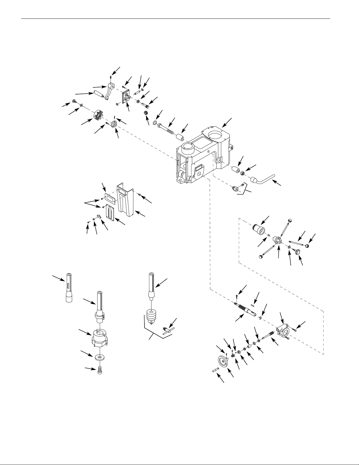
AASSSSEEMMBBLLYY
Refer to Figures 3, 6, 7, 8 and 10.
CAUTION: Do not attempt assembly if parts are missing. Use this
manual to order replacement parts.
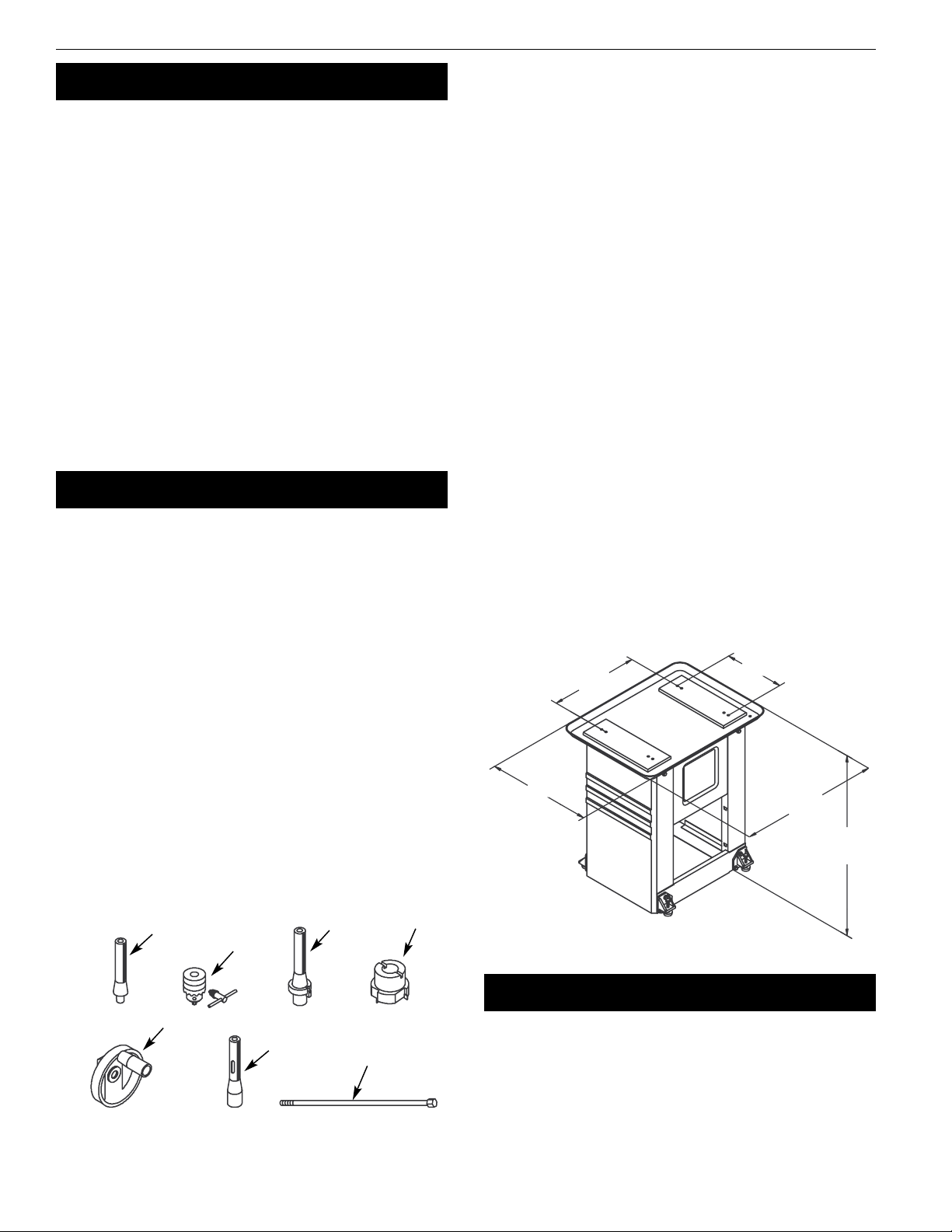
MILL DRILL INSTALLATION
Mill drill must be mounted to a flat level surface. Use shims or
machine mounts if necessary. Do not mount machine in direct sun-
light. Heat caused by sunlight may deform plastic parts on
machine.
If stand is used, be sure to bolt mill drill to stand and level stand to
floor to minimize vibration. Use hex head bolts, hex nuts and level-
ing pads (Figure 10, Ref. Nos. 8, 11 and 12) to align the mill drill.
Tighten all nuts and bolts that may have loosened in shipping.
Secure mill drill base to stand or bench.
ASSEMBLE STAND (OPTIONAL)
Refer to Figure 10.
•Place both supports (Ref. No. 5) upside down on floor.
•Attach feet (Ref. No. 9) and plate (Ref. No. 7) to each support
using hex head bolts, washers and hex nuts (Ref. No. 2, 3 and 4).
Finger tighten fasteners at this time.
•Repeat on other side of supports with feet and plate (Ref. No.
14).
•Turn unit right side up.
•Install left and right panels (Ref. Nos. 6 and 13). Gently spread
supports so that tabs on panels fit into slots located on sup-
ports.
•Secure all fasteners from steps 2 and 3.
•Place chip pan (Ref. No. 1) on top of supports, locating the bot-
tom rail of the chip pan inside the supports.
•Secure chip pan to supports using hex head bolts and flat
washers (Ref. Nos. 2 and 3).
MOUNT MILL DRILL TO STAND
Refer to Figure 10.
Place mill drill on stand with mounting holes aligned. Bolt mill drill
base to stand with four hex head bolts and four flat washers (Ref.
Nos. 3 and 10).
Palmgren Operating Manual & Parts List 80161 & 70104

4
ASSEMBLY (CONTINUED)
MOUNT TABLE HANDWHEELS
Refer to Figure 8.
Thread table handles (Ref. No. 11) into table handwheels (Ref. No.
12). Secure handwheels to left and right ends of longitudinal lead
screw (Ref. No. 35) using set screws (Ref. No. 30).
INSTALL DRAWBAR AND ARBOR
Refer to Figures 6 and 7.
Insert draw bar (Figure 7, Ref. No. 52) into top of spindle. Be sure
that arbor and spindle taper are clean of all dirt, metal chips, oil,
etc. Insert chuck or face mill arbor (Figure 6, Ref. Nos. 52 and 55)
into spindle and rotate arbor to engage spindle key in arbor key-
way. Push arbor into spindle and thread draw bar into end of arbor.
Use a wrench to tighten draw bar securely.
IINNSSTTAALLLLAATTIIOONN
POWER SOURCE
Refer to Figure 3, page 4.
The Palmgren mill drill is prewired for 230 volts, 60 Hz, single-phase
power. A qualified electrician should wire a 240 volt, 20 AMP, 3-
prong plug (not included) to mill drill line cord. Use only NEMA rec-
ommended plugs, connectors and receptacles rated on 20 amps
minimum.
To use machine with a 115 volt, 60Hz, single-phase power supply:
WARNING: All electrical connections must be performed by a
qualified electrician.
•Change motor wiring to 115 volts. Refer to motor nameplate
for wiring schematic.
•Change setting of voltage select switch (Figure 9, Ref. No. 36) to
110 volts.
•Attach a 125 volt, 20 or 30 Amp, 3-prong plug (not included) to
the mill drill line cord. Use only NEMA recommended plugs,
connectors and receptacles rated on 20 amps minimum.
OOPPEERRAATTIIOONN
Refer to Figures 4, 6, 7 and 8.
ADJUSTING HEAD
Refer to Figures 6 and 8.
Loosen hex nut (Figure 6, Ref. No. 24) with wrench (Figure 6, Ref. No.
23). Head can be rotated 360° around column by hand. Be sure rack
(Figure 8, Ref. No. 6) does not bind. Raise or lower head by turning
head adjusting crank (Figure 6, Ref. No. 34). Be sure to tighten both
hex nuts after adjusting head.
CHANGING SPEED
Palmgren mill drill is a 12-speed machine. Spindle speeds are
determined by location of V-belts on three pulleys.
Always push stop button and disconnect power from machine
before changing speeds.
Open cover access door. Pulley cover top can be tilted back for
speed changes by sliding latches outward. Be sure to close cover
when finished.
Loosen handle (Ref. No. 26) and push motor mount plate (Ref. No.
33) toward head.Tighten handle.
Loosen transmitting pulley base (Ref. No. 41) by loosening hex
head bolts (Ref. No. 46). Place V-belts on pulleys for desired speed
as shown in speed chart (See Figure 4, page 5).
Tension front V-belt (Ref. No. 53) by pushing middle pulley away
from spindle pulley.Tighten hex head bolts.
Loosen handle and push motor mount plate away from head to
tension rear V-belt. Tighten handle. Check belt tension and adjust if
necessary. Close pulley cover.
Secure pulley cover latches.
SPINDLE OPERATION
Refer to Figures 6 and 7.
Palmgren mill drill is equipped with spindle fine feed handwheel
and spindle depth lockdown handle.
Engage fine feed handwheel (Figure 6, Ref. No. 2) by rotating pin-
ion knob clockwise (Figure 6, Ref. No. 17) until tight. Disengage fine
feed by loosening pinion knob.
Spindle depth can be locked into position by tightening quill lock
handle (Figure 7, Ref. No. 23). Bring spindle down to desired posi-
tion and tighten quill lock handle to hold spindle position.
Palmgren Operating Manual & Parts List 80161 & 70104
Spindle RPM Belt Location
120 A1-4Z
90 B2-4Z
230 A1-3Y
285 C3-4Z
370 B2-3Y
440 A1-2X
770 D4-3Y
1040 C3-2X
1220 B2-1W
1450 D4-2X
1800 C3-1W
2500 D4-1W
O.L.
20A
O.L.
10A
OF2
(3A)
PE L1 L2
3
3
000
4
4
8
3
5
2
SB1
SB2 QS1
SB3
KM
KM
0V 24V
110V
110V
220V 220V
110V
220V
M
Figure 3 – Wiring Schematic

5
Palmgren Operating Manual & Parts List 80161 & 70104
OPERATION (CONTINUED)
DEPTH STOP
Refer to Figures 6 and 7.
Repeated operations where depth of cut is consistent are made
easier by using depth scale (Figure 6, Ref. No. 47) and depth setting
knob (Figure 7, Ref. No. 9).
Depth of cut is shown on depth scale and indicated by depth indi-
cator (Figure 6, Ref. No. 48).
Depth of cut is set by rotating depth setting knob until desired
depth is obtained.
HANDWHEEL SCALES
Refer to Figure 8.
The cross feed handwheel and right-hand longitudinal handwheel
are equipped with graduated collars.
One full rotation of handwheel moves table .100”. Handwheel
scales are graduated in .001”.
Scales are used when precise movement of table is required.
Scales can be zeroed by loosening dial screw (Ref. No. 16) and
rotating lead screw dial (Ref. No. 13) until zero marks are aligned.
Tighten dial screw.
TABLE STOP BLOCKS
Refer to Figure 8.
Longitudinal travel can be limited to make repeated operations
easier by using the table stop blocks (Ref. No. 40).
Table stop blocks are positioned to contact table stop bracket (Ref.
No. 26) limiting table travel.
Adjust stop blocks by loosening socket head bolts (Ref. No. 39) and
moving stop blocks to desired position. Secure socket head bolts.
TABLE LOCKS
Refer to Figure 8.
Mill drill table can be locked into position using table lock handles
(Ref. No. 27).
Longitudinal position is secured by tightening lock handles on
front of saddle.
Cross feed position is secured by tightening lock handles on right
side of saddle.
REMOVE ARBOR
Loosen draw bar with wrench and remove arbor from spindle.
MMAAIINNTTEENNAANNCCEE
Refer to Figures 5, 6, 7 and 8.
Keep all moving parts and surfaces clean of dirt, metal chips, etc.
Keep a light coating of oil on all exposed surfaces, including table
top and slots, all dovetail way surfaces, lead screws, rack and col-
umn.
Replace worn V-belts.
Check electrical connections and replace any worn or frayed wires
or line cords.
Replace worn way cover.
GIB ADJUSTMENT
Refer to Figures 5 and 8.
Palmgren mill drill is equipped with adjustable gibs (See Figure 5)
on longitudinal and cross feed that eliminate excess play in table
as dovetail ways wear over time.
Rotating gib adjustment bolts (Ref. No. 25) clockwise tightens
dovetail ways. Adjust gib bolts until a slight drag is felt when mov-
ing the table with handwheels. Loosen bolts if table is too tight.
REPLACE RETURN SPRING
Refer to Figure 6 and 7.
Return spring may wear after extended use and will need replace-
ment. If spindle does not return to full up position when released,
then replace return spring.
CAUTION: Spring is under tension and may tend to twist forceful-
ly when relaxed.
To replace return spring, push spindle to fully up position and lock
it in place by tightening quill lock handle (Figure 7, Ref. No. 23).
Loosen spring cover knob (Figure 6, Ref. No. 38) slowly and careful-
ly rotate spring and cover clockwise to relax spring tension.
Remove spring cover knob and washer (Figure 6, Ref. No. 38 and
40). When tension is released, rotate spring and cover clockwise to
release spring from mounting screw.
Remove spring and cover. Place new spring over pinion shaft and
slide slot at end of spring over mounting screw. Press spring and
cover against head casting.
Replace washer and spring cover knob. Rotate cover counterclock-
wise to tension spring. Rotate cover approximately three full turns
and tighten cover knob. Release quill lock handle.
Test spring tension by pulling down on crank handle (Figure 6, Ref.
No. 19). Adjust spring tension as needed.
Overtightening spring causes quill to return with excessive
force damaging quill and rubber bumper (Figure 7, Ref. Nos. 5
and 19).
Figure 4 – Spindle Speed Chart
B
C
A1
2
3
4
Motor
Spindle
Spindle
Rotation
D
X
Y
W
Z
Figure 5 – Gib Adjustment
Gib
Adjustment
Bolts

6
Palmgren Operating Manual & Parts List 80161 & 70104
MAINTENANCE (CONTINUED)
LUBRICATION
Refer to Figures 6, 7 and 8.
Use medium weight, non-detergent oil.
DAILY:
•Apply five to six drops of oil on splines at the top of spindle
(Figure 7, Ref. No. 4).
•Be sure cross feed lead screw (Figure 8, Ref. No. 20) is clean of
dirt and metal chips. Oil if necessary.
WEEKLY:
•Oil cross feed lead screw (Figure 8, Ref. No. 20).
•Oil dovetail ways.
MONTHLY:
•Oil handwheel bearings through oil fittings (Figure 8, Ref. No.
19).
•Oil gear rack on back of quill where pinion shaft (Figure 6, Ref.
No. 15) engages quill (Figure 7, Ref. No. 5).
•Oil depth stop lead screw (Figure 7, Ref. No. 17).
•Apply bearing grease to rack (Figure 8, Ref. No. 6) and pinion
shaft (Figure 6, Ref. No. 15). Remove pinion knob and handle
base (Figure 6, Ref. Nos. 17 and 20) to expose pinion shaft.
•Grease longitudinal lead screw (Figure 8, Ref. No. 35).

7
TTRROOUUBBLLEESSHHOOOOTTIINNGG
Palmgren Operating Manual & Parts List 80161 & 70104
SYMPTOM
Motor does not run when start button is
pushed
Motor overheats
Spindle overheats
Lack of power at spindle
Cutting tool chattering
Spindle does not return to full “up” position
Excessive backlash in lead screws
Excessive noise
Excessive play in table
POSSIBLE CAUSES
1. No power to motor
2. Blown fuse on control box
3. Defective switch or contactor
1. Low voltage to motor
2. V-belts too tight
3. Too deep or too fast a cut
4. Worn contacts in contactor
1. Poor quill bearing lubrication
2. Spindle bearings too tight
3. Mill drill operated at high speeds
for extended period
V-belts loose
1. Spindle bearings loose
2. Table is loose
3. Worn spindle bearings
4. Head clamp bolts loose
1. Poorly adjusted return spring
2. Worn return spring
Worn lead screw nuts
1. Loose spindle bearings
2. Loose motor pulley
Table is loose
CORRECTIVE ACTION
1. Check electrical connector and
circuit breaker or fuse
2. Correct wiring problem and
replace fuse
3. Replace defective parts
1. Check voltage
2. Tension belts properly
3. Reduce cut depth or speed
4. Replace contactor
1. Lubricate bearings with bearing grease
2. Adjust bearings so that spindle
does not bind
3. Allow mill drill to cool
Tension V-belts properly
1. Tighten bearings
2. Adjust table and saddle gibs
3. Replace bearings
4. Tighten bolts
1. Increase return spring tension
2. Replace return spring
Replace lead screw nuts
1. Adjust bearings properly
2. Tighten pulley set screws
Adjust table gibs properly

8
Palmgren Operating Manual & Parts List 80161
Figure 6 – Repair Parts Illustration for Head
35
36
34
33 32 31
29
28
27
60
59
30
37
55
54
53
52
38
44
25
24
23
18
22
21
20
16
15
14
11
8
46
3
5
12
13
10
9
8
7
63
2
1
50
64
49
48
47
46
57
51
42
61
58
40
56
41
19
62
39
17
45
26
43

9
Palmgren Operating Manual & Parts List 80161
RREEPPLLAACCEEMMEENNTTPPAARRTTSSLLIISSTTFFOORRHHEEAADD
Ref.
No. Description Part No. Qty.
1 Handle 05911.01 1
2 Handwheel 17147.00 1
3 8-1.25 x 10mm Set screw * 1
4 6-1.0 x 8mm Set screw * 1
5 Fine feed scale 05895.01 1
6 5-0.8 x 10mm Pan head screw * 2
7 Worm cover 05894.01 1
8 6202ZZ Ball bearing 1L015 2
9 Spacer 05893.00 1
10 3 AMI-15 Retaining ring 00533.00 1
11 Worm shaft 05892.01 1
12 Fine feed housing 05891.00 1
13 8-1.25 x 25mm Socket head bolt * 2
14 7 x 7 x 20mm Key 05889.00 1
15 Pinion shaft 17148.00 1
16 5-0.8 x 10mm Flat head screw * 1
17 Pinion knob 05883.00 1
18 Handle knob 05886.00 3
19 Crank handle 17218.00 3
20 Handle base 17149.00 1
21 Compression spring 17150.00 1
22 Ring gear housing 17151.00 1
23 Wrench 17152.00 1
24 12-1.75mm Hex nut * 1
25 Bushing 17153.00 1
26 Head 17154.09 1
27 12-1.75 x 120mm Hex head bolt * 1
28 Worm shaft 05900.00 1
29 Bushing 05972.00 1
30 Worm gear 05899.00 1
31 3 AMI-14 Retaining ring 05989.00 2
32 Worm gear shaft 16488.00 1
33 6-1.0 x 20mm Socket head bolt * 4
Ref.
No. Description Part No. Qty.
34 Head adjusting crank 05901.01 1
35 Handle 04006.00 1
36 10-1.5 x 8mm Set screw * 1
37 Pinion housing 16489.00 1
38 Knob 05866.01 1
39 Retaining clip 15350.00 1
40 1/4” Flat washer * 1
41 Return spring and cover 05881.00 1
42 Strain relief 00582.00 1
43 Spring base 05882.00 1
44 6-1.0 x 12mm Washer head screw * 4
45 Front cover 05875.01 1
46 Warning label 05877.01 1
47 Depth scale 05876.01 1
48 Depth indicator 05874.00 1
49 3mm Flat washer * 1
50 3-0.5 x 16mm Pan head screw * 1
51 3.5-1.3 x 8mm Tapping screw 17155.00 6
52 R8 to JT3 Arbor 15214.00 1
53 JT3 Chuck with key (Ref. No. 54) 15351.00 1
54 Chuck key 15352.00 1
55 Face mill arbor 17156.00 1
56 Face milling cutter 15354.00 1
57 Retaining plate 15355.00 1
58 10-1.5 x 25mm Socket head bolt * 1
59 Bushing 16491.00 1
60 32 x 7mm Oil seal 16492.00 1
61 3 x 12mm Spring pin 06396.00 2
62 10mm Flat Washer * 1
63 5-0.8 x 20mm Pan head screw * 3
64 R8/3MT Adapter 17157.00 1
∆Operator’s Manual 20953.09 1
* Standard hardware item available locally.

10
Palmgren Operating Manual & Parts List 80161
Figure 7 – Repair Parts Illustration for Head
56
53
45
44
43
42
41
40
40
39
67
37
35
38
55
66
67
62
63
59
51
57
71
60
61
18
61
69
48
58
50
24
23
22
21
20 25
26
27
28
29
32
68
30
31
31
33
19 17
14
15
16
8
7
6
5
11
13
12
10
9
2
1
43
34
31
31
46
52
54
47
65
50
50
70
39
49
64
36

Ref.
No. Description Part No. Qty.
1 45 x 72 x 8mm Oil seal 15357.00 1
2 30207 J-N Taper bearing 05855.00 1
3 4-0.7 x 8mm Socket head bolt * 1
4 Spindle 17158.00 1
5 Quill 05852.01 1
6 30206 J-N Taper bearing 05856.00 1
7 30mm Keyed washer 17159.00 1
8 30-1.25mm Spanner nut 05858.00 2
9 Depth setting knob 05867.01 1
10 4 x 18mm Spring pin 02783.00 1
11 Rod bushing 17160.00 1
12 Rod base 05869.01 1
13 6-1.0mm Hex nut * 1
14 16-2.0mm Hex jam nut * 1
15 Depth indicator block 17161.00 1
16 6-1.0 x 50mm Hex head bolt * 1
17 Depth stop lead screw 05872.00 1
18 Spacer 17171.00 1
19 Rubber bumper 05859.00 1
20 Rod bushing 17162.00 1
21 10-1.5 x 40mm Dog point set screw 02576.00 1
22 10-1.5mm Hex nut * 1
23 Quill lock handle 17163.00 1
24 Quill lock bushing 17164.00 1
25 Quill lock sleeve 16499.00 1
26 Handle 17165.00 1
27 Compression spring 05905.00 1
28 Tension rod 05906.00 1
29 Rod cap 05907.01 1
30 8-1.25 x 25mm Hex head bolt * 4
31 8mm Flat washer * 14
32 10-1.5 x 25mm Hex head bolt * 2
33 Motor mount plate 05912.01 1
34 8-1.25mm Hex nut * 4
35 8-1.25 x 10mm Set screw * 2
36 Motor pulley 05914.00 1
Ref.
No. Description Part No. Qty.
37 V-belt 05665.00 1
38 Motor and key 17206.00 1
39 Pulley cover 17166.00 1
40 16-2.0mm Hex nut * 2
41 Transmitting pulley base 17167.00 1
42 Transmitting pulley shaft 17168.00 1
43 Transmitting pulley 05910.00 1
44 6204ZZ Bearing 00989.00 2
45 54mm Retainer ring 05975.00 1
46 8-1.25 x 35mm Hex head bolt * 2
47 8-1.25 x 16mm Hex head bolt * 5
48 41mm Retainer ring 05973.00 1
49 Grommet 04076.00 1
50 5-0.8 x 12mm Pan head screw * 6
51 Spindle pulley 05864.00 1
52 Draw bar 05921.00 1
53 V-belt 04106.00 1
54 Spindle lock nut 05343.01 1
55 Cover access door 17169.00 1
56 Draw bar cover 17170.00 1
57 6mm Flat washer * 2
58 Cover 15343.00 1
59 Plate 17172.00 1
60 Spindle taper sleeve 05345.01 1
61 6009ZZ Bearing 05860.00 2
62 Cover 15345.00 1
63 4-0.7 x 6mm Pan head screw * 2
64 12-1.75mm Hex nut * 1
65 Switch plate 17173.00 1
66 5mm Flat washer * 2
67 5-0.8mm Hex nut * 4
68 10mm Flat washer * 2
69 86mm Retainer ring 05902.00 1
70 Clamp 02702.00 1
71 6-1.0 x 15mm Socket head bolt * 2
11
Palmgren Operating Manual & Parts List 80161
RREEPPLLAACCEEMMEENNTTPPAARRTTSSLLIISSTTFFOORRHHEEAADD
* Standard hardware item available locally.

12
Palmgren Operating Manual & Parts List 80161
Figure 8 – Repair Parts Illustration for Base
1
20
17
17
18
17
17
11
11
12
12
14
14
13
19
16
15
47
26
21
30
30
48
24
10
25
25
31
44
43
24
27
27
38
31
29
28
31
36
23
45
22
24
19
13
48
11 12
32
30
40
39
42 19
47
33
37
6
3
4
7
5
8
7
8
34
46
49
16
15
5
9
41
40
39
35
41
2

13
Palmgren Operating Manual & Parts List 80161
∆Not Shown.
* Standard hardware item available locally.
Ref.
No. Description Part No. Qty.
1 Base 17174.09 1
2 Column 16378.09 1
3 Column cap 17175.00 1
4 8-1.25 x 8mm Set screw * 1
5 12mm Flat washer * 8
6 Rack 05926.00 1
7 12-1.75 x 50mm Hex head bolt * 8
8 12-1.75mm Lock washer * 8
9 Saddle 17176.00 1
10 Saddle gib 17177.00 1
11 Handle 04006.00 3
12 Handwheel 05931.00 3
13 Lead screw dial 17178.00 2
14 Lead screw coupling 05933.00 2
15 5 x 40mm Spring pin 05934.00 2
16 6-1.0 x 10mm Dial screw 17179.00 2
17 51103 Thrust bearing 05935.00 4
18 Cross feed flange 05936.01 1
19 Oil fitting 05979.00 3
20 Cross feed lead screw 05937.01 1
21 Cross feed lead screw nut 17180.00 1
22 8-1.25 x 50mm Socket head bolt * 1
23 Pin 17181.00 1
24 8-1.25 x 20mm Socket head bolt * 6
25 Gib adjustment bolt 17182.00 2
26 Table stop bracket 05939.00 1
Ref.
No. Description Part No. Qty.
27 Table lock handle 15348.00 4
28 Way cover 05941.01 1
29 Lower cover plate 05942.00 1
30 1/4-20 x 3/8“ Set screw * 3
31 8-1.25 x 15mm Hex head bolt * 6
32 Left lead screw coupling 17183.00 1
33 Left lead screw flange 05945.00 1
34 Right lead screw flange 05946.01 1
35 Longitudinal lead screw 05947.01 1
36 Longitudinal lead screw nut 17184.00 1
37 Table 17185.00 1
38 Table gib 17186.00 1
39 6-1.0 x 16mm Socket head bolt * 2
40 Stop block 05951.01 2
41 Stop block nut 17187.00 2
42 10-1.5 x 10mm Set screw * 1
43 1/4 x 1” Brass dowel pin 16496.00 2
44 8-1.25 x 25mm Socket head bolt * 2
45 6-1.0 x 12mm Washer head screw * 6
46 Cover plate 15332.09 1
47 Scale 15334.00 2
48 Rivet 01286.00 4
49 Column support 17188.09 1
Recommended Accessories
∆Power Feed Accessory 80162 1
RREEPPLLAACCEEMMEENNTTPPAARRTTSSLLIISSTTFFOORRBBAASSEE

14
Palmgren Operating Manual & Parts List 80161
Figure 9 – Repair Parts Illustration for Control Assembly
13
13
13
16
16
14
15
19
18
17
47
20
27
8
5
3
1
46
18
4
21
22
11
52
50
31
32
30
33
34
35
37
48 48
39
49
45
51
44
43
42
41
40
25
26
38
37
36
3
3
28
29
22
24
23
2
10
9
9
6
7

15
Palmgren Operating Manual & Parts List 80161
∆Not Shown.
* Standard hardware item available locally.
Ref.
No. Description Part No. Qty.
1 Control box face plate 17189.00 1
2 Gasket 17190.00 1
3 4-0.7 x 8mm Round head screw * 7
4 Emergency stop switch 15337.00 1
5 Power lamp 15338.00 1
6 Stop switch 15339.00 1
7 Start switch 15310.00 1
8 Control box housing 17191.09 1
9 Grommet 04076.00 2
10 Limit switch cord 15312.00 1
11 8-1.25 x 16mm Socket head bolt * 2
12 5/16” Flat washer * 2
13 Motor cord 17192.00 1
14 Cover 15314.09 1
15 4-0.7 x 6mm Pan head screw * 1
16 Control cord 15315.00 1
17 Upper connector 15316.00 1
18 6mm Flat washer * 2
19 Cord cover 15317.00 1
20 Lower connector 15318.00 1
21 3-0.5 x 16mm Pan head screw * 2
22 3mm Flat washer * 4
23 Limit switch 15319.00 1
24 3-0.5mm Hex nut * 2
25 Strain relief 00582.00 1
26 Line cord 05968.00 1
27 6-1.0 x 12mm Pan head screw * 2
28 Plate 17193.00 1
29 Terminal block 17194.00 1
Ref.
No. Description Part No. Qty.
30 Fuse holder 17205.00 1
31 Plate 17195.09 1
32 Transformer 17196.00 1
33 Recepticle 16376.00 2
34 3.5-0.6 x 10mm Oval countersunk * 4
screw
35 4.2-1.4 x 16mm Tapping screw 17197.00 2
36 Voltage select switch 17204.00 1
37 4.2-1.4 x 8mm Tapping screw 17198.00 6
38 5-0.8 x 25mm Socket head bolt * 1
39 Magnetic contactor 17199.00 1
40 Grounding block 17200.00 1
41 5mm Serrated washer * 3
42 5-0.8 x 6mm Round head screw * 3
43 4-0.7 x 15mm Pan head screw * 4
44 Plate 16497.00 1
45 Lamp assembly 17201.00 1
46 6-1.0 x 12mm Pan head screw * 2
47 4mm Flat washer * 1
48 4mm Lock washer * 6
49 20A Circuit breaker 17203.00 1
50 3A Fuse 16479.00 1
51 5mm Flat washer * 1
52 10A Circuit breaker 17202.00 1
∆Lamp bulb 15328.00 1
∆Lamp switch 15329.00 1
∆Lamp circuit board 17219.00 1
∆Lamp lens 17220.00 1
RREEPPLLAACCEEMMEENNTTPPAARRTTSSLLIISSTTFFOORRCCOONNTTRROOLLAASSSSEEMMBBLLYY

16
Figure 10 – Repair Parts Illustration for Optional Mill Drill Stand
4
4
5
6
2
2
1
7
11
11
10
3
13
14
12
12
3
3
3
8
8
5
9
9
9
9
Palmgren Operating Manual & Parts List 70104
* Standard hardware item available locally.
Ref.
No. Description Part Number Qty.
1 Chip pan 17413.00 1
2 8-1.25mm Hex nut * 12
3 8mm Flat washer * 24
4 8-1.25 x 25mm Hex head bolt * 20
5 Support 15301.00 2
6 Right panel 15302.00 1
7 Right plate 15303.00 1
8 12-1.75 x 50mm Hex head bolt * 4
9 Foot 15304.00 4
10 8-1.25 x 120mm Hex head bolt * 4
11 12-1.75mm Hex nut * 4
12 Leveling pad 15306.00 4
13 Left panel 15307.00 1
14 Left plate 15308.00 1
RREEPPLLAACCEEMMEENNTTPPAARRTTSSLLIISSTTFFOORROOPPTTIIOONNAALLMMIILLLLDDRRIILLLLSSTTAANNDD

17
Service Record
Palmgren Mill Drill and Mill Drill Stand
Date Maintenance Performed Replacement Components Required
Palmgren Operating Manual & Parts List 80161 & 70104

18
Palmgren Operating Manual & Parts List 80161 & 70104
NOTES

19
Palmgren Operating Manual & Parts List 80161 & 70104
NOTES

WWAARRRRAANNTTYY
FULL TWO YEAR WARRANTY ON PALMGREN MILL DRILL AND OPTIONAL MILL DRILL STAND
If within two full years from the date of purchase, this Palmgren Mill Drill and Mill Drill Stand fails due to a defect in material or
workmanship, Palmgren will repair it free of charge.
To order parts for a non-warranty repair, please contact your preferred Palmgren distributor. To obtain the names of Palmgren
distributors or to arrange warranty return, please call Palmgren Steel Products directly at (800) 621-6145.
This warranty gives you specific legal rights and you may have other rights which vary from state to state.
Palmgren Steel Products, Inc., 914 N. Kilbourn Avenue, Chicago, IL 60651-3426
Palmgren Operating Manual & Parts List 80161 & 70104
This manual suits for next models
1
Table of contents
Other Palmgren Drill manuals