Palmgren 80156 User manual

operating manual & parts list 80155 and 80156
15″
HEAVY DUTY BENCH AND FLOOR MODEL
DRILL PRESS
Read carefully and follow all safety rules and operating instructions before
first use of this product.
32111.09-0910

DESCRIPTION
Palmgren Drill Presses feature a heavy cast iron base, column collar,
work table and head.Work table height is adjustable using rack
and pinion.Table can be tilted 45° both right and left, and rotates
360° on a vertical axis.Work table surface is precision ground and
features T-slots for secure, accurate mounting of workpiece and
also a coolant trough. Digital readout displays spindle depth and
RPM. Other features of the Palmgren drill press are an enclosed ball
bearing quill assembly, quick belt change and tension mechanism,
positive quick-adjust feed depth stop and a 1⁄2HP, 1725 RPM
motor. Chuck and chuck arbor are included.
Palmgren drill presses are ideal for use in home shops, mainte-
nance shops and light industrial applications. Spindle speeds are
adjustable for drilling steel, cast iron, aluminum, wood and plastic.
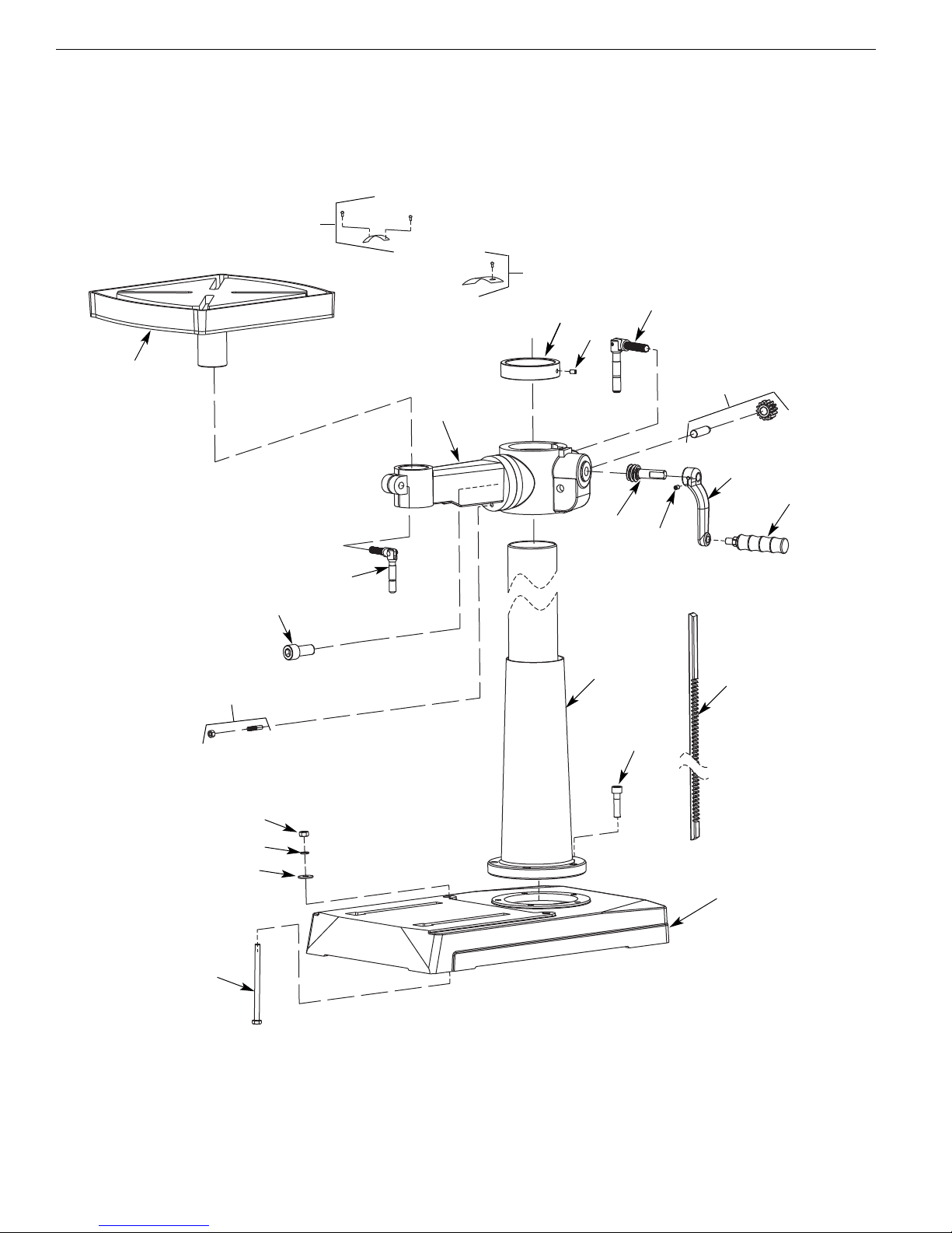
UNPACKING
Refer to Figure 1.
WARNING: Be careful not to touch overhead power lines, piping,
lighting, etc., if lifting equipment is used. Drill press weighs up to
204 lbs, proper tools, equipment and qualified personnel should be
employed in all phases of unpacking and installation.
Crates should be handled with care to avoid damage from drop-
ping, bumping, etc. Store and unpack crates with correct side up.
After uncrating drill press, inspect carefully for any damage that
may have occurred during transit. Check for loose, missing or dam-
aged parts. If any damage or loss has occurred, claim must be filed
with carrier immediately. Check for completeness. Immediately
report missing parts to dealer.
Drill press is shipped unassembled.Locate and identify the follow-
ing assemblies and loose parts:
A Head Assembly
B Table
CBase
D Column, Rack and Ring Assembly (80155)
E Table Arm and Bracket Assembly (80155)
F Column and Bracket Assembly (80156)
G Feed Handle Knob
H Feed Handle
I Table Handle
J Table Handle Knob
K Center Pulley Assembly
Not Shown: Drill Chuck with Key, Arbor, Drill Drift, M8 x 24 Key,
Plate, M6 x 16 Tap Screw, Column Lock Handle (80155),Table Lock
Handle (80155),Worm Gear (80155), five M10 x 40 Socket Head
Bolts, 3, 5 and 8mm Hex Wrenches, two M8 x 125 Hex Head Bolts,
two M8 Lock Washers, four M8 Flat Washers, and two M8 Hex Nuts.
IMPORTANT: The tool has been coated with a protective coating.
In order to ensure proper fit and operation the coating must be
removed. Remove coating with mild solvents such as mineral spir-
its and a soft cloth. Nonflammable solvents are recommended.
After cleaning, cover all exposed surfaces with a light coating of oil.
Paste wax is recommended for table top.
CAUTION: Never use highly volatile solvents. Avoid getting clean-
ing solution on paint as it may tend to deteriorate these finishes.
Use soap and water on painted components.
SPECIFICATIONS
Chuck size . . . . . . . . . . . . . . . . . . . . . . . . . . . . . . . . . . . . . . . . . . . 1⁄25 - 5⁄8”,JT3
Spindle taper . . . . . . . . . . . . . . . . . . . . . . . . . . . . . . . . . . . . . . . . . . . . . . . . MT2
Spindle travel . . . . . . . . . . . . . . . . . . . . . . . . . . . . . . . . . . . . . . . . . . . . . . . . . . 5”
Quill diameter . . . . . . . . . . . . . . . . . . . . . . . . . . . . . . . . . . . . . . . . . . . . . 2.047”
Quill collar diameter . . . . . . . . . . . . . . . . . . . . . . . . . . . . . . . . 2.60” (66mm)
Column diameter . . . . . . . . . . . . . . . . . . . . . . . . . . . . . . . . . . . . . . . . . . . 2.87”
Speeds . . . . . . . . . . . . . . . . . . . . . . . . . . . . . . . . . . . . . . . . . . . . . . . . . . . . . . . . 16
RPM . . . . . . . . . . . . . . . . . . . . . . . . . . . . . . . . . . . . . . . . . . . . . . . . . . . . 138-3476
Swing . . . . . . . . . . . . . . . . . . . . . . . . . . . . . . . . . . . . . . . . . . . . . . . . . . . . . . . . 15”
Table size . . . . . . . . . . . . . . . . . . . . . . . . . . . . . . . . . . . . . . . . . . . . . . 111/2x 13”
Table working surface . . . . . . . . . . . . . . . . . . . . . . . . . . . . . . . . . . 111/2x 13”
T-Slots (diagonal) . . . . . . . . . . . . . . . . . . . . . . . . . . . . . . . . . . . . . . 4 x 14mm
Base size:
80155 . . . . . . . . . . . . . . . . . . . . . . . . . . . . . . . . . . . . . . . . . . . . . . . 105/8”x 181⁄8”
80156 . . . . . . . . . . . . . . . . . . . . . . . . . . . . . . . . . . . . . . . . . . . . . . 123/4”x 193⁄4”
Base working surface:
80155 . . . . . . . . . . . . . . . . . . . . . . . . . . . . . . . . . . . . . . . . . . . . . . . . . 93/8” x 9 3⁄8”
80156 . . . . . . . . . . . . . . . . . . . . . . . . . . . . . . . . . . . . . . . . . . . . . . . . . 101/4” x 11”
Drilling capacity (cast iron) . . . . . . . . . . . . . . . . . . . . . . . . . . . . . . . . . . . . 5⁄8”
Distance, spindle to table:
80155 . . . . . . . . . . . . . . . . . . . . . . . . . . . . . . . . . . . . . . . . . . . . . . . . . . . . 15/8-13”
80156 . . . . . . . . . . . . . . . . . . . . . . . . . . . . . . . . . . . . . . . . . . . . . . . . . . 31⁄4-261/4”
Distance, spindle to base:
80155 . . . . . . . . . . . . . . . . . . . . . . . . . . . . . . . . . . . . . . . . . . . . . . . . . . . . . . 231/8”
80156 . . . . . . . . . . . . . . . . . . . . . . . . . . . . . . . . . . . . . . . . . . . . . . . . . . . . . . 463/16”
Overall height:
80155 . . . . . . . . . . . . . . . . . . . . . . . . . . . . . . . . . . . . . . . . . . . . . . . . . . . . . . . . 43”
80156 . . . . . . . . . . . . . . . . . . . . . . . . . . . . . . . . . . . . . . . . . . . . . . . . . . . . . . 661⁄2”
Weight:
80155 . . . . . . . . . . . . . . . . . . . . . . . . . . . . . . . . . . . . . . . . . . . . . . . . . . . . 174 lbs
80156 . . . . . . . . . . . . . . . . . . . . . . . . . . . . . . . . . . . . . . . . . . . . . . . . . . . . .193 lbs
Shipping weight:
80155 . . . . . . . . . . . . . . . . . . . . . . . . . . . . . . . . . . . . . . . . . . . . . . . . . . . . 185 lbs
80156 . . . . . . . . . . . . . . . . . . . . . . . . . . . . . . . . . . . . . . . . . . . . . . . . . . . . .204 lbs
Motor . . . . . . . . . . . . . . . . 1⁄2HP, 120/240 V, 8.6/4.3 A, 1725 RPM, 60 Hz
SAFETY RULES
PROPOSITION 65 WARNING: Some dust created by power
sanding, sawing, grinding, drilling and other construction activities
contains chemicals known to the state of California to cause can-
cer, birth defects or other reproductive harm.
Some examples of these chemicals are:
•Lead from lead-based paints.
•Crystalline silica from bricks and cement and other masonry
products.
2
Palmgren Operating Manual & Parts List 80155 and 80156
Figure 1 – Unpacking
AB
C
E
D
FG
H
IJK

3
•Arsenic and chromium from chemically-treated lumber.
Your risk from these exposures vary, depending on how often you
do this type of work.To reduce your exposure to these chemicals:
work in a well ventilated area and work with approved safety
equipment. Always wear OSHA/NIOSH approved, properly fitting
face mask or respirator when using such tools.
Before any work is done, carefully read the cautions listed.Working
safely prevents accidents.
BE PREPARED FOR JOB
•Wear proper apparel. Do not wear loose clothing, gloves, neck-
ties, rings, bracelets or other jewelry which may get caught in
moving parts of machine.
•Wear protective hair covering to contain long hair.
•Wear safety shoes with non-slip soles.
•Wear safety glasses which comply with United States ANSI
Z87.1. Everyday glasses have only impact resistant lenses.They
are NOT safety glasses.
•Wear face mask or dust mask if cutting operation is dusty.
•Be alert and think clearly.Never operate power tools when
tired, intoxicated or when taking medications that cause
drowsiness.
WORK AREA SHOULD BE READY FOR JOB
•Keep work area clean. Cluttered work areas and work benches
invite accidents.
•Do not use power tools in dangerous environments. Do not use
power tools in damp or wet locations. Do not expose power
tools to rain.
•Work area should be properly lighted.
•Proper electrical outlet should be available for tool.
Three-prong plug should be plugged directly into properly
grounded, three-prong receptacle.
•Extension cords should have a grounding prong, and the three
wires of the extension cord should be of the correct gauge.
•Keep visitors at a safe distance from work area.
•Keep children out of workplace. Make workshop childproof. Use
padlocks, master switches or remove switch keys to prevent
any unintentional use of power tools.
TOOL SHOULD BE MAINTAINED
•Always unplug tool prior to inspection.
•Read operating instructions manual for specific maintaining
and adjusting procedures.
•Keep tool lubricated.
•Use sharp cutters and keep the tool clean for safest operation.
•Remove adjusting tools. Form the habit of checking that adjust-
ing tools are removed before turning on the machine.
•Keep all parts in working order. Check to determine that the
guard or other parts will operate properly and perform their
intended function.
•Check for damaged parts. Check for alignment of moving parts,
binding, breakage, mounting and any other condition that may
affect a tool’s operation.
•Damaged parts should be properly repaired or replaced.Do not
perform makeshift repairs. (Use the parts list provided to order
replacement parts.)
KNOW HOW TO USE TOOL
•Use the right tool for the job. Do not force tool or attachment
to do a job for which it was not designed.
•Disconnect tool when changing accessories such as bits, cut-
ters and the like.
•Avoid accidental start-up. Make sure switch is in OFF position
before plugging in.
•Do not force tool. It will work most efficiently at the rate for
which it was designed.
•Handle workpiece correctly. Secure work with clamps or vise.
Leave hands free to operate machine, Protect hands from
possible injury.
•Never leave a tool running unattended.Turn the power off and
do not leave tool until it comes to a complete stop.
•Do not overreach. Keep proper footing and balance.
•Never stand on tool. Serious injury could occur if tool is tipped
or if cutter is unintentionally contacted.
•Keep hands away from moving parts and cutting surfaces.
•Know your tool. Learn its operation, application and specific
limitations.
•Feed work into a bit or cutter against the direction of rotation
of bit or cutter.
•Turn the machine off if it jams. A cutter jams when it digs too
deeply into the workpiece. (The motor force keeps it stuck in
workpiece.)
•Use recommended accessories. Refer to page 11.Use of
improper accessories may cause risk of injury to persons.
•Clamp workpiece or brace against column to prevent rotation.
•Use recommended speed for drill accessory and workpiece
material.
WARNING: Think Safety! Safety is a combination of operator com-
mon sense and alertness at all times when drill press is being used.
ASSEMBLY
MOUNT COLUMN ASSEMBLY TO BASE
Refer to Figure 7.
•Place base (Ref. No. 1) on flat level surface.
•Mount column assembly (Ref. No. 7) to base using five socket
head bolts (Ref. No. 6).
MOUNT TABLE (80155)
Refer to Figure 7.
•Loosen set screw (Ref. No. 17). Remove rack and rack retaining
ring (Ref. Nos. 8 and 16) from column (Ref. No.7).
•Place worm gear (Ref. No. 20) into hole of table bracket (Ref. No.
12).
•Place rack inside table bracket assembly (Ref. No. 12) with large,
unmachined portion of rack to the top. Slide rack into slot in
bracket so that teeth of rack engage pinion gear in bracket.
•Slide table assembly with rack over column. Place bottom end
of rack inside beveled edge of column flange.
•Slide rack retaining ring over column with beveled edge down.
Position ring against top of rack so that rack is in beveled edge
of ring. Secure ring with set screw (Ref. No.17).
•Rotate table assembly around column. Adjust rack retaining
ring as necessary to prevent binding of rack.
•Attach crank handle (Ref. No. 22) to shaft on worm gear, rotate
worm gear to remove slack, and shoulder crank handle against
table bracket. Secure handle with set screw. (Ref. No. 21).
•Thread handle (Ref. No. 18) into table bracket assembly.Position
bracket over the center of the base and secure bracket in
position.
•Slide table (Ref. No. 13) into hole in table arm. Secure table with
table locking handle (Ref. No. 11).
Palmgren Operating Manual & Parts List 80155 and 80156

4
MOUNT TABLE (80156)
Refer to Figure 7.
•Attach crank handle (Ref. No. 22) to shaft of worm gear (Ref. No.
20), rotate worm gear to remove slack, and shoulder crank han-
dle with set screw (Ref. No. 21). Attach crank handle knob (Ref.
No.23) to handle.
•Slide table (Ref. No. 13) into hole in table arm. Secure table with
table locking handle (Ref. No. 11).
MOUNT HEAD ASSEMBLY
Refer to Figure 9.
WARNING: Although compact, the drill press head assembly is
heavy. Two people are required to mount the drill press head
assembly onto the column.
•Slide drill press head assembly onto top of column.
•Position head so that it is centered over base.
•Secure head by tightening the set screws (Ref. No. 36) on the
right side of the head casting.
MOUNT QUILL FEED HANDLE ASSEMBLY
Refer to Figure 8.
•Place key (Ref. No. 32) into keyway of pinion (Ref. No. 33).
•Place quill feed handle assembly (Ref. No. 34) over pinion.
•Secure handle assembly with tap head screw (Ref. No. 36) and
plate (Ref. No. 35).
•Thread quill feed knob (Ref. No. 37) into quill feed handle
assembly.
INSTALL CENTER PULLEY ASSEMBLY
Refer to Figures 8 and 9.
•Loosen belt tension knobs (Fig. 8, Ref. No. 38) and use handle
(Fig. 8, Ref. No. 43) to move motor toward front of drill press.
•Open cover of pulley housing (Fig. 9, Ref. No. 2) and insert cen-
ter pulley assembly (Fig. 8, Ref. No. 8) into the head casting.
•Choose a speed from Figure 5 or the pulley housing speedchart
and connect spindle pulley to center pulley with front drive
belt (Fig. 8, Ref. Nos. 2, 7 and 8). Connect center pulley to motor
pulley with rear drive belt (Fig. 8, Ref. Nos. 8, 54 and 55).
NOTE: Front drive belt is type 254J4 and rear drive belt is type
290J4.
•Turn handle (Fig. 8, Ref. No. 43) to move motor toward rear of
drill press and tighten belt tension knob (Fig. 8, Ref. No. 38).
MOUNT DRILL CHUCK AND ARBOR
Refer to Figure 8.
•Be sure spindle taper, arbor taper and chuck taper are clean
and dry.
•Use the provided chuck key (Ref. No. 31) to adjust the jaws of
the chuck (Ref. No. 30) until they are recessed inside the drill
chuck body.
•Place drill chuck on a workbench face down. Arbor (Ref. No. 29)
has a short taper and a long taper. Place short taper into top of
drill chuck and tap with a rubber or wooden mallet.
•Slide arbor into the spindle (Ref. No. 24) while slowly rotating
drill chuck. Spindle has a rectangular pocket in which the tang
fits into. Once tang is oriented correctly, drill chuck will not
rotate without turning the spindle.
•Tap the end of drill chuck with a rubber or wooden mallet to
seat it into the spindle.
Hardware (Two M8 x 125 hex head bolts, M8 lock washers, M8 hex
nuts and four M8 flat washers) has been provided for mounting
the drill press to a wood base plate.This is recommended if you
intend to place the drill press on a mobile base.The minimum
recommended size of the wood base plate is 3⁄4x 24 x 24”.
INSTALLATION
Refer to Figures 2, 3 and 4.
MOUNT DRILL PRESS
•Drill press must be mounted to flat level surface. Use shims or
machine mounts if necessary. Do not mount drill press in direct
sunlight.
•Be sure to bolt drill press to floor or bench securely to prevent
tipping and minimize vibration.
•Tighten all nuts and bolts that may have loosened during
shipment.
POWER SOURCE
The motor is designed for operation on the voltage an frequency
specified.Normal loads will be handled safely on voltages not more
than 10% above or below the specified voltage.
Running the unit on voltages which are not within the range may
cause overheating and motor burn out.Heavy loads require that the
voltage at motor terminals be no less than the voltage specified.
GROUNDING INSTRUCTIONS
WARNING: Improper connection of equipment grounding con-
ductor can result in the risk of electrical shock. Equipment should
be grounded while in use to protect operator from electrical shock.
Check with a qualified electrician if grounding instructions are not
understood or if in doubt as to whether the tool is properly
grounded.
This tool is equipped with an approved 3-conductor cord rated up
to 300V and a 3-prong grounding type plug rated at 115V (See
Figure 2) for your protection against shock hazards.
Grounding plug should be plugged directly into a properly
installed and grounded 3-prong grounding-type receptacle, as
shown (Figure 2).
Do not remove or alter grounding prong in any manner. In the
event of a malfunction or breakdown, grounding provides a path
of least resistance for electrical shock.
WARNING: Do not permit fingers to touch the terminals of plug
when installing or removing from outlet.
Plug must be plugged into matching outlet that is properly
installed and grounded in accordance with all local codes and
ordinances. Do not modify plug provided. If it will not fit in outlet,
have proper outlet installed by a qualified electrician.
Inspect tool cords periodically, and if damaged, have repaired by
an authorized service facility.
Green (or green and yellow) conductor in cord is the grounding
wire. If repair or replacement of the electric cord or plug is neces-
sary, do not connect the green (or green and yellow) wire to a live
terminal.
Where a 2-prong wall receptacle is encountered, it must be
replaced with a properly grounded 3-prong receptacle installed in
accordance with National Electric Code and local codes and ordi-
nances.
Palmgren Operating Manual & Parts List 80155 and 80156
Figure 2 – 3-Prong Receptacle
Properly Grounded Outlet
Grounding Prong
3-Prong Plug

WARNING: This work should be performed by a qualified electrician.
A temporary 3-prong to 2-prong grounding adapter (See Figure 3)
is available for connecting plugs to a two pole outlet if it is
properly grounded.
Do not use a 3-prong to 2-prong grounding adapter unless permit-
ted by local and national codes and ordinances.
(A 3-prong to 2-prong grounding adapter is not permitted in
Canada.) Where permitted, the rigid green tab or terminal on the
side of the adapter must be securely connected to a permanent
electrical ground such as a properly grounded water pipe, a prop-
erly grounded outlet box or a properly grounded wire system.
Many cover plate screws, water pipes and outlet boxes are not
properly grounded.To ensure proper ground, grounding means
must be tested by a qualified electrician.
EXTENSION CORDS
•The use of any extension cord will cause some drop in voltage
and loss of power.
•Wires of the extension cord must be of sufficient size to carry
the current and maintain adequate voltage.
•Use the table to determine the minimum wire size (A.W.G.)
extension cord.
•Use only 3-wire extension cords having 3-prong grounding
type plugs and 3-pole receptacles which accept the tool plug.
•If the extension cord is worn, cut, or damaged in any way,
replace it immediately.
EXTENSION CORD LENGTH (120 VOLTS)
Wire Size A.W.G.
Up to 25 ft. . . . . . . . . . . . . . . . . . . . . . . . . . . . . . . . . . . . . . . . . . . . . . . . . . . . . .18
25-50 ft. . . . . . . . . . . . . . . . . . . . . . . . . . . . . . . . . . . . . . . . . . . . . . . . . . . . . . . .16
50-100 ft. . . . . . . . . . . . . . . . . . . . . . . . . . . . . . . . . . . . . . . . . . . . . . . . . . . . . . .14
100-150 ft. . . . . . . . . . . . . . . . . . . . . . . . . . . . . . . . . . . . . . . . . . . . . . . . . . . . . .12
NOTE: Using extension cords over 150 ft. long is not recommend-
ed.
EXTENSION CORD LENGTH (240 VOLTS)
Wire Size A.W.G.
Up to 50 ft. . . . . . . . . . . . . . . . . . . . . . . . . . . . . . . . . . . . . . . . . . . . . . . . . . . . . .18
50-100 ft. . . . . . . . . . . . . . . . . . . . . . . . . . . . . . . . . . . . . . . . . . . . . . . . . . . . . . .16
100-200 ft. . . . . . . . . . . . . . . . . . . . . . . . . . . . . . . . . . . . . . . . . . . . . . . . . . . . . .16
200-300 ft. . . . . . . . . . . . . . . . . . . . . . . . . . . . . . . . . . . . . . . . . . . . . . . . . . . . . .14
NOTE: Using extension cords over 300 ft.long is not recommended.
POWER SOURCE
Drill press requires a 120/240 volt, 60 Hz power source.
To use the drill press with a 240V power supply, have a qualified
electrician attach a 240 volt, 20/30A three-prong plug onto drill
press line cord.
ELECTRICAL CONNECTIONS
Refer to Figure 4.
WARNING: All electrical connections must be performed by a
qualified electrician. Make sure unit is off and disconnected from
power source while motor is mounted, connected, reconnected or
anytime wiring is inspected.
•The motor should be wired for 120 volts and clockwise rotation
as viewed from shaft end of motor.
•A label on the motor describes the possible wiring configura-
tions.There are many different possible combinations, so only
the diagram provided with the motor should be used.
•The power supply to motor is controlled by a push button
switch. Power lines are connected to the quick connect termi-
nals of the switch.
•The green ground line must remain securely fastened to the
motor ground terminal to provide proper grounding.
•To operate drill press at 240 volts, rewire motor as shown in
Figure 4 and replace line cord plug with a 240 volt, 15A, 3-prong
plug.If motor label has a different wiring configuration, use the
motor label diagram to rewire motor.
OPERATION
Refer to Figures 5-9.
WARNING: Read and understand operating instructions and
parts manual before operating this machine.
CAUTION: The operation of any power tool can result in foreign
objects being thrown into the eyes, which can result in severe eye
damage. Always wear safety glasses complying with United States
ANSI Z87.1 (shown on package) before commencing power tool
operation.
STARTING AND STOPPING THE DRILL PRESS
Refer to Figure 9.
WARNING: Be sure drill bit is not in contact with workpiece when
motor is started. Start motor and allow bit to come up to full speed
before drilling.
•The ON/OFF siwtch (Ref. No. 15) is located on the front of the
head casting.
•To turn the drill press on, push green ON button. Always allow
drill bit to come up to speed before drilling.
•To turn the drill press off, press the large red OFF paddle or lift
the paddle and press directly on the red OFF button. Do not
leave drill press until the bit has come to a complete stop.
SPEED ADJUSTMENTS
Refer to Figures 5 and 8.
WARNING: Be sure drill press is turned off and is disconnected
from power source before adjusting speeds.
•To change spindle speed, loosen motor lock knobs (Ref. No. 38),
turn handle (Ref. No. 43) to move motor toward front of drill
press.This will loosen the belt and permit relocating the belt to
the desired pulley groove for the required spindle speed (See
Figure 5, page 6).
•After belt has been repositioned, turn handle to move motor
toward rear of drill press and tighten motor lock knobs.
•Check belt for proper tension and make any final adjustment. A
belt is properly tensioned when light pressure applied to mid-
point of the belt produces about 1/2”deflection.
TABLE ADJUSTMENTS
Refer to Figure 7.
•Height adjustments:To adjust table, loosen locking handle (Ref.
No.18) and turn crank handle (Ref. No. 23) to desired height.
Immediately retighten table bracket locking handle.
Figure 4 – Wiring Schematic for Motor
120 Volts
131324 24
240 Volts
5
Palmgren Operating Manual & Parts List 80155 and 80156
Figure 3 – 2-Prong Receptacle with adapter
Grounding Lug
Adapter
3-Prong Plug
2-Prong Receptacle
Make sure this is
Connected to a known
Grounded Receptacle

•Rotation of work table : Loosen table locking handle (Ref. No.
18) and rotate table (Ref. No. 13) to desired position and
retighten handle.
•Tilting work table: Loosen table bolt (Ref.No.10). Remove pin
and nut (Ref. No. 9).To do this, tighten nut until pin slips out easi-
ly. Tilt table to desired angle up to 45° and retighten table bolt.
Reinsert pin and nut when returning the table to 0° position.
•To obtain more distance between chuck and table, the work
table can be rotated 180° and base can be used as a work sur-
face.This permits drilling of larger objects.
•Clamp table securely after adjustments have been made.
DEPTH STOP ADJUSTMENT
Refer to Figure 8.
To control drilling depth, use scale (Ref. No. 16) to adjust to desired
depth. Depress and hold pin, slide depth stop nut (Ref. No. 15)
along lead screw until bottom edge of nut coincides with the
desired depth on the scale, then release pin. Use this feature to drill
more than one hole to the same depth.
MOUNT DRILL BIT
Refer to Figure 8.
WARNING: Be sure drill press is turned off and is disconnected
from power source before adjusting speeds.
•Place drill bit in jaws of drill chuck.
•Tighten chuck with drill chuck key. Be sure to tighten the chuck
using all three key positions on the chuck body and remove
chuck key.
•Use only the self-ejecting chuck key (Ref. No. 31) supplied with
this drill press, or a duplicate key. Use of any other key might
allow start up with the key still in the chuck. An airborne key
could strike the operator and cause injury.
REMOVE THE CHUCK
Refer to Figures 8 and 9.
•Rotate quill feed handle (Fig. 8, Ref. No. 34) until slot is exposed
in the side of the quill (Fig. 8, Ref. No. 24). Lock quill in position
using handle (Fig. 9, Ref. No. 30).
•Rotate spindle until inner slot is aligned with outer slot.You will
see through spindle when slots are properly aligned.
•Insert the drift key (Fig. 8, Ref. No. 25) into the slots and tap
lightly with hammer.The arbor and chuck will drop from spindle.
DIGITAL DISPLAY PANEL
Refer to Figure 6.
•Display panel ‘A’ shows the depth of the spindle and spindle
RPM.
•Button ‘B’ turns power on and off to Display ‘A’.
•Button ‘C’: Press once for spindle depth in inches; press again
for spindle depth in mm; press once again for spindle RPM.
•Button ‘D’ resets display at zero for spindle depth.
6
3476
2362
1660
566
497
344
257
in/mm
5/16 7.9
5/8 15.9
7/8 22.2
11⁄431.8
11⁄431.8
15⁄841.3
2 50.8
in/mm
3/16 4.8
3/8 9.5
1/2 12.7
3/4 19.0
3/4 19.0
7/8 22.2
1 25.4
in/mm
11/64 4.4
11/32 8.7
15/32 11.9
11/16 17.5
11/16 17.5
3/4 19.0
——
in/mm
5/32 4.0
5/16 7.9
7/16 11.1
5/8 15.9
5/8 15.9
13/16 20.6
——
in/mm
7/64 2.8
1/4 6.4
11/32 8.7
1/2 12.7
1/2 12.7
5/8 15.9
——
in/mm
3/32 2.4
5/32 4.0
1/4 6.4
3/8 9.5
3/8 9.5
1/2 12.7
——
in/mm
1/16 1.6
1/8 3.2
3/16 4.8
5/16 7.9
5/16 7.9
7/16 11.1
9/16 14.3
in/mm
1/32 0.8
1/16 1.6
1/8 3.2
1/4 6.4
1/4 6.4
3/8 9.5
1/2 12.7
RPM Wood Zinc Diecast Alum. & Brass Plastic Cast Iron &
Bronze
Steel - Mild &
Malleable
Steel - Cast &
Med. Carbon
Steel -
Stainless
& Tool
E
D
C
B
A
Z
Y
X
W
5
4
3
2
1
Motor
Spindle
138
257
304
344
461
497
566
708
755
927
1491
1660
1761
2362
2444
3476
A1-5Z
B2-5Z
A1-4Y
C3-5Z
D4-5Z
A1-3X
B2-4Y
A1-2W
C3-4Y
B2-3X
E5-4Y
D4-3X
C3-2W
D4-2W
E5-3X
E5-2W
RPM
Belt
Location
Figure 5 – Spindle Speed Adjustment
Figure 6 – Digital Display Panel
ZEROUNITS
A
B
CD
0.000
mm
Palmgren Operating Manual & Parts List 80155 and 80156

7
MAINTENANCE
WARNING: Turn switch off and remove plug from power source
outlet before maintaining or lubricating your drill press
DRIVE BELT
Replace drive belt when worn.
LUBRICATION
Refer to Figures 7 and 8.
The ball bearings are lubricated at the factory and need no further
lubrication. Using 20wt. non detergent oil, periodically lubricate
the splines (grooves) in the spindle and the rack (teeth on the
quill) as follows:
•Lower quill assembly (Figure 8, Ref. No. 24) all the way down.
•Apply lubricant around the inside of the hole in the spindle
pulley (Figure 8, Ref. No. 2).
•Apply lubricant to rack (teeth) on quill (Figure 8, Ref. No. 24)
while extended below drill press head.
•Apply lubricant to rack and pinion gear (Figure 7, Ref. Nos. 8
and 19) on column and table assembly.
CLEAN MOTOR
Frequently blow out any dust that may accumulate inside motor. If
power cord is worn, cut or damaged in any way, have it replaced
immediately.
Palmgren Operating Manual & Parts List 80155 and 80156

8
SYMPTOM
Spindle does not turn
Noisy spindle
Noisy operation
Bit burns or smokes
Excessive drill runout or wobble
Drill bit binds in workpiece
POSSIBLE CAUSES
1. No power to drill press
2. Defective switch
3. Defective motor
Defective bearings
1. Incorrect belt tension
2. Dry spindle
3. Loose spindle
4. Loose motor pulley
1. Incorrect speed
2. Chips not coming out of table
3. Dull bit
4. Feeding too slow
5. Bit not lubricated
6. Bit running backwards
1. Bent bit
2. Bit not properly installed in chuck
3. Chuck not properly installed
4. Worn spindle bearings
1. Workpiece pinching bit or excessive feed
2. Improper belt tension
3. Workpiece not supported or clamped
properly
CORRECTIVE ACTION
1. Check wiring, fuse or circuit breaker
2. Replace switch
3. Replace motor
Replace bearings
1. Adjust tension
2. Lubricate spindle, See Lubrication, page 6
3. Tighten pulley nut
4. Tighten set screw in pulley
1. Change speed
2. Retract bit frequently to clear chips
3. Sharpen or replace bit
4. Feed faster; enough to allow drill to cut
5. Lubricate bit
6. Check motor rotation to be sure it is
clockwise facing shaft end
1. Replace bit
2. Install bit properly
3. Install chuck properly
4. Replace bearings
1. Support or clamp work, decrease feed
pressure
2. Adjust tension
3. Support or clamp workpiece securely
TROUBLESHOOTING
Palmgren Operating Manual & Parts List 80155 and 80156

9
Palmgren Operating Manual & Parts List 80155 and 80156
Service Record
Palmgren 15″Bench and Floor Model Drill Presses
DATE MAINTENANCE PERFORMED REPLACEMENT PARTS REQUIRED

11
19
10
8
12
18
6
5
4
15
16
17
7
21
23
22
20
13
14
2
3
9
1
10
Figure 7 - Replacement Parts Illustration for Base
Palmgren Operating Manual & Parts List 80155 and 80156

11
Palmgren Operating Manual & Parts List 80155 and 80156
REPLACEMENT PARTS LIST FOR BASE
* Standard hardware item available locally.
ΔNot Shown.
Ref. Part Numbers for:
No. Description 80155 80156 Qty.
1 Base 32172.00 32177.00 1
2 8-1.25 x 125mm Hex head bolt * * 2
3 8mm Flat washer * * 4
4 8mm Lock washer * * 2
5 8-1.25mm Hex nut * * 2
6 10-1.5 x 40mm Socket head bolt * * 5
7 Column assembly 32173.00 32178.00 1
8 Rack 32174.00 32179.00 1
9 Taper pin and nut 32116.00 32116.00 1
10 5⁄8-11 x 11⁄2”Socket head bolt * * 1
11 Table locking handle 32117.00 32117.00 1
12 Table bracket and support assembly 32175.00 32175.00 1
13 Table 32119.00 32119.00 1
14 Indicator set 31977.00 31977.00 1
15 Scale set 31974.00 31974.00 1
16 Rack retaining ring 32176.00 32176.00 1
17 6-1.0 x 8mm Set screw * * 1
18 Locking handle 31976.00 31976.00 1
19 Pinion gear and shaft 32122.00 32122.00 1
20 Worm gear 32123.00 32123.00 1
21 6-1.0 x 10mm Set screw * * 1
22 Crank 32125.00 32125.00 1
23 Handle 31982.00 31982.00 1
ΔOperator’s manual 32111.09 32111.09 1
Recommended Accessories
Δ4”Angle Vise 11351 11351 1
Δ4”Drill Press Vise 12352 12352 1
Δ4”Standard Vise 12403 12403 1
Δ6”Quick Grip Vise 12621 12621 1
Δ6”Standard Vise 12601 12601 1
Δ6”Cross Vise 30601 30601 1

6
49
34
35
39
38
38
33
31
30
32
7
8
910 11 12
13
22
20
21
25
29
26
28
27
24
47
43
4
4
5
5
45
44
46 50
51
52
55
57
56
54
53
42
41
40
37
36
23
2
1
3
19
18
17
16
14
15
48 48
12
Palmgren Operating Manual & Parts List 80155 and 80156
Figure 8 - Replacement Parts Illustration for Spindle and Drive

13
Palmgren Operating Manual & Parts List 80155 and 80156
Ref.
No. Description Part No. Qty.
1 Spindle nut 32126.00 1
2 Spindle pulley 32127.00 1
3 Spindle sleeve 32128.00 1
4 Circlip 32129.00 2
5 6205-2RS Ball bearing 09624.00 2
6 Spacer 32130.00 1
7 Front drive belt 32180.00 1
8 Center pulley assembly 32132.00 1
91⁄2”-20 Hex nut * 2
10 12mm Flat washer * 1
11 Cap cover with spring 32133.00 1
12 2.5 x 10mm Spring pin 04084.00 1
13 Spring seat 32134.00 1
14 4-0.7 x 12mm Tap screw 32135.00 3
15 Depth stop nut assembly 32029.00 1
16 Scale 32028.00 1
17 10-1.5mm Fiber hex nut * 1
18 Depth stop lead screw 32026.00 1
19 6-1.0mm Hex nut * 1
20 12-1.75 Fiber hex nut * 1
21 Depth stop collar 32136.00 1
22 6-1.0 x 8mm Set screw 01043.00 1
23 6-1.0 x 45mm Hex head bolt * 1
24 Lower spindle and quill assembly 32137.00 1
25 Drift key 18909.00 1
26 3mm Hex wrench 00149.00 1
27 5mm Hex wrench 00150.00 1
28 8mm Hex wrench 00889.00 1
29 MT2/JT3 Arbor 27926.00 1
Ref.
No. Description Part No. Qty.
30 JT3 chuck with key 32138.00 1
31 Chuck key 32139.00 1
32 8 x 7 x 24mm Key 32020.00 1
33 Pinion 32140.00 1
34 Quill feed handle with grips 32141.00 1
35 Plate 32017.00 1
36 6-1.0 x 16mm Tap screw 32004.00 1
37 Quill feed knob 32018.00 1
38 Belt tension knob 32142.00 2
39 Cam 32143.00 1
40 Pin 32144.00 1
41 8-1.25 x 16mm Hex head bolt * 1
42 3AMI-15 Retaining ring 00533.00 1
43 Belt tension handle 32145.00 1
44 Line cord 32146.00 1
45 Left motor tension rod 32147.00 1
46 Right motor tension rod 32148.00 1
47 8-1.25 x 20mm Hex head bolt * 4
48 8mm Flat washer * 8
49 Bracket 32149.00 1
50 8-1.25mm Hex nut * 4
51 Motor 32181.00 1
52 5 x 5 x 40mm Key 07885.00 1
53 8-1.25 x 12mm Set screw * 1
54 Motor pulley 32151.00 1
55 Rear drive belt 32182.00 1
56 12mm Lock washer * 2
57 12-1.75mm Hex nut * 2
ΔMotor capacitor 32185.00 1
REPLACEMENT PARTS LIST FOR SPINDLE AND DRIVE
* Standard hardware item available locally.
ΔNot Shown.

14
Palmgren Operating Manual & Parts List 80155 and 80156
Figure 9 - Replacement Parts Illustration for Head
35
23
14
13
29
36
20
30
4
39
7
6
9
8
28
43
5
3
2
1
22
33
34
26
11
37
38
44
42
12
27
32
27
25
21
31
7
7
19
18
17
15
16
24
40
10
41

Ref.
No. Description Part No. Qty.
1 Knob assembly 32037.00 1
2 Pulley housing 32183.00 1
3 Grommet 32041.00 1
4 Speed sensor assembly 32042.00 1
5 Bracket 32043.00 1
6 5mm Flat washer * 2
7 5-0.8 x 10mm Pan head screw * 2
8 4mm Flat washer * 2
9 4-0.7 x 10mm Socket head bolt * 2
10 6-1.0 x 12mm Cheese head screw 32155.00 4
with flat washers
11 Foam washer 32154.00 4
12 5-0.8 x 16mm Pan head screw * 1
13 Clamp 32156.00 1
14 4-0.7 x 20mm Pan head screw * 2
15 Switch assembly 32157.00 1
16 Display cover 32158.00 1
17 6-1.0 x 30mm Pan head screw * 4
18 Switch housing 32159.00 1
19 Circuit board 32160.00 1
20 Circuit board shield 32161.00 1
21 3-0.5 x 5mm Pan head screw * 4
22 3mm Flat washer * 2
Ref.
No. Description Part No. Qty.
23 3-0.5 x 45mm Pan head screw * 2
24 6-1.0 x 12mm Tap screw 32252.00 2
25 Bracket 32050.00 1
26 5 x 8mm Spring pin 32051.00 2
27 5-0.8 x 8mm Pan head screw * 2
28 5mm Serrated washer * 4
29 Ground Label 32162.00 1
30 Quill lock handle 32163.00 1
31 10mm Lock washer * 1
32 10-1.5mm Hex jam nut * 1
33 Threaded pin 32164.00 1
34 Transfer shaft assembly 32059.00 1
35 Potentiometer shaft assembly 32060.00 1
36 10-1.5 x 12mm Set screw * 2
37 6 x 24mm Spring pin 04092.00 2
38 Seal 32171.00 1
39 Plate 32184.00 1
40 Cover 32061.00 1
41 Clamp 32170.00 1
42 Clamp 32167.00 1
43 Seal 32168.00 1
44 5-0.8 x 8mm Pan head screw * 1
15
Palmgren Operating Manual & Parts List 80155 and 80156
REPLACEMENT PARTS LIST FOR HEAD
* Standard hardware item available locally.

WARRANTY
Palmgren warrants their products to be free of defects in material or workmanship.This warranty does not cover defects due
directly or indirectly to misuse, abuse, normal wear and tear, failure to properly maintain the product, heated, ground or otherwise altered, or
used for a purpose other than that for which it was intended.The warranty does not cover expendable and/or wear parts (i.e. v-belts, coated
screws, abrasives), damage to tools arising from alteration, abuse or use other than their intended purpose, packing and freight.The duration
of this warranty is expressly limited to one year parts and labor, unless otherwise noted below beginning from the date of delivery to the
original user.The Palmgren products carry the following warranties on parts with a 1 year warranty on labor:
•USA Machine vises – Lifetime
•IQ Machine vises – Lifetime
•Bench vises – Lifetime
•Positioning tables – Lifetime
•Bench grinders & buffers – 3 years
•Tapping machines – 2 years
•Drilling machines – 2 years
•Finishing machines – 2 years
•Band saws – 2 years
•Work stands – 2 years
•Arbor presses – 2 years
•Metal framing equipment – 2 years
•Accessories – 1 year
The obligation of Palmgren is limited solely to the repair or replacement, at our option, at its factory or authorized repair agent of any part
that should prove deficient.Purchaser must lubricate and maintain the product under normal operating conditions at all times. Prior to oper-
ation
become familiar with product and the included materials, i.e. warnings, cautions and manuals. Failure to follow these instructions will void
the warranty.
This warranty is the purchaser’s exclusive remedy against Palmgren for any deficiency in its products. Under no circumstances is Palmgren
liable for any direct, indirect, incidental, special or consequential damages including lost profits in any way related to the use or inability to
use our products.This warranty gives you specific legal rights which may vary from state to state.
SERVICE & REPAIR
1. If a Palmgren product requires a repair or warranty service DO NOT return the product to the place of purchase.
2. All warranty related work must be evaluated and approved by Palmgren.
3. Prior to returning any item the user must obtain factory approval and a valid RGA number.
4. For instructions and RGA number call toll free (800) 621-6145.
Palmgren Operating Manual & Parts List 80155 and 80156
This manual suits for next models
1
Other Palmgren Drill manuals