PalmSens EmStat User manual

Getting started with the EmStat
Development Board
Development board for EmStat module: OEM Interface for electrochemical sensors
Last revision: October 24, 2017
© 2016 PalmSens BV
www.palmsens.com

Getting started with the EmStat Development Board
Important before you start
unpacking
Please read this quick start guide carefully before unpacking the boards from their
antistatic bags or using the kit, as it contains important information on how to avoid
damage to the PCB’s.
Customer support
Questions regarding the contents of this document or the products described in this document can be
directed to PalmSens BV via:
-the contact form on the website: www.palmsens.com
-an e-mail to [email protected] ,
-or by telephone: +31 30 2459211
Information contained in this publication regarding device applications and the like is
provided only for your convenience and may be superseded by updates. It is your
responsibility to ensure that your application meets with your specifications.
PALMSENS BV MAKES NO REPRESENTATIONS OR WARRANTIES OF ANY KIND
WHETHER EXPRESS OR IMPLIED, WRITTEN OR ORAL, STATUTORY OR OTHERWISE,
RELATED TO THE INFORMATION, INCLUDING BUT NOT LIMITED TO ITS CONDITION,
QUALITY, PERFORMANCE, MERCHANTABILITY OR FITNESS FOR PURPOSE.
PalmSens BV disclaims all liability arising from this information and its use. Use of
Palmsens BV’s products as critical components in life support systems is not
authorized except with express written approval by Palmsens BV. No licenses are
conveyed, implicitly or otherwise, under any Palmsens BV intellectual property rights.
The EmStat board can be damaged by static electricity (electrostatic
discharge or ESD). Please take adequate precautions against static
discharge during handling.

October 2017 - PalmSens BV 1
Getting started with the EmStat Development Board
Contents
1EmStat development board features ................................................................................................. 2
Circuit protection ...................................................................................................................... 2
Power options .......................................................................................................................... 2
Communication options............................................................................................................ 3
Potentiostat interfaces .............................................................................................................. 3
Arduino Integration ................................................................................................................... 3
Other ........................................................................................................................................ 3
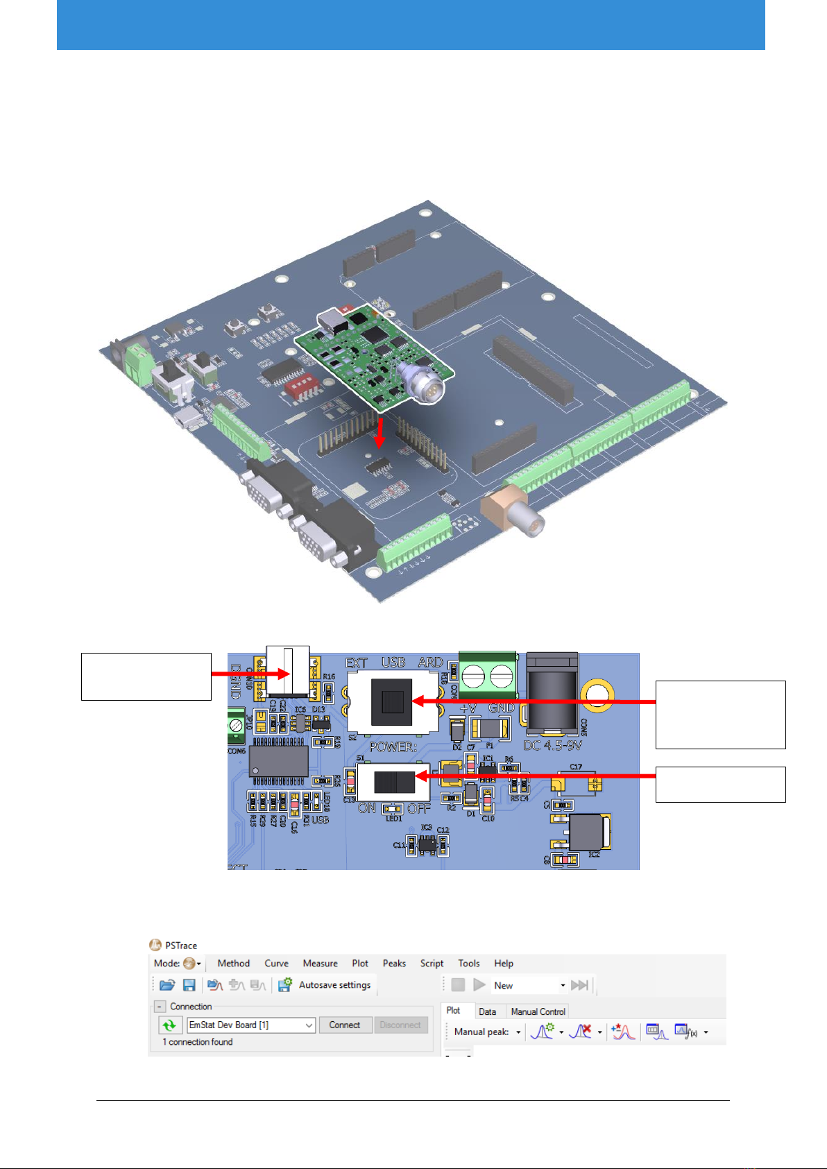
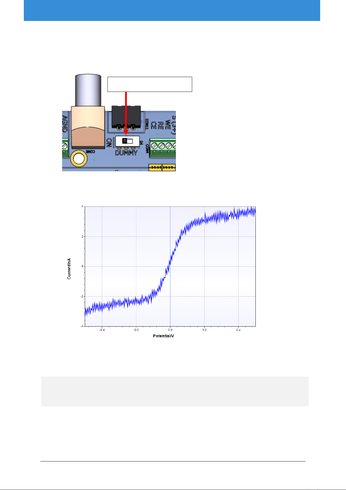
2First measurement using PSTrace ..................................................................................................... 4
3Getting started with the PalmSens Embedded SDK libraries ............................................................. 6
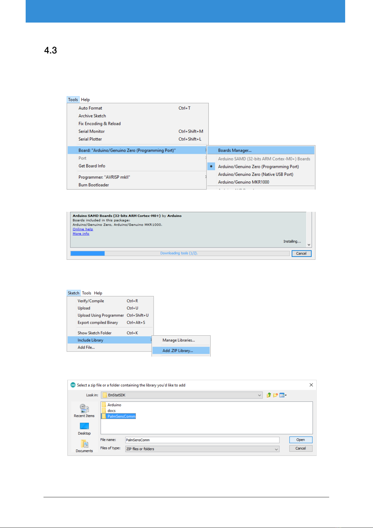
4Getting started with Arduino/Genuino................................................................................................ 7
Requirements ........................................................................................................................... 7
Preparing the EmStat dev. board for use with Arduino ............................................................. 7
Running the EmStat SDK Example for Arduino......................................................................... 8
4.3.1 Controlling the Arduino via terminal....................................................................................... 9
5Power supply options...................................................................................................................... 11
6Communication options .................................................................................................................. 11
PalmSens AUX pinout............................................................................................................. 12
RS232 communications ......................................................................................................... 12
Serial communication at TTL level........................................................................................... 12
7Pin descriptions............................................................................................................................... 13
Pinout of LEMO sensor socket (CON8)................................................................................... 13
Pinout of SPE connector (CON11) .......................................................................................... 13
CON4 pinout .......................................................................................................................... 13
CON5 pinout .......................................................................................................................... 14
8Adding a multiplexer........................................................................................................................ 15
9Noise considerations ....................................................................................................................... 16
Shielding can .......................................................................................................................... 16
10 Changing EmStat baudrate settings ............................................................................................ 17
11 Updating EmStat firmware........................................................................................................... 17
Programming the EmStat with custom firmware ..................................................................... 17
Updating the EmStat’s firmware via serial connection............................................................. 18
12 EmStat3 and EmStat3+ module specifications ............................................................................ 19
Appendix A: Change EmStat USB connection to virtual COM port ......................................................... 20

October 2017 - PalmSens BV 2
Getting started with the EmStat Development Board
1EmStat development board features
The EmStat-series are potentiostats with an embedded microcontroller. They provide all the major
potentiostatic techniques with automatic current ranging and peripheral control.
The EmStat development board contains the following features:
Figure 1- EmStat Development board features
Circuit protection
The following circuit protection mechanisms have been implemented in the dev. board:
▪All digital IO's have over-voltage, reverse-voltage, over-current, and ESD protection.
▪Analog IO's are buffered on-board for impedance isolation, over-voltage and reverse-voltage
protection, and ESD protection.
▪Valid input supply range of 3-12VDC, with over-current and reverse-voltage protection, and a
regulated +5V supply for the EmStat to ensure correct operation and preventing damage.
Power options
The development board can be powered by:
▪DC adaptor,
▪screw terminals,
▪via USB,
▪or via the Arduino.
See for more information section “Power supply options”on page 11.
Schematics of the development board can be found
on the CD that was supplied with the development board.

October 2017 - PalmSens BV 3
Getting started with the EmStat Development Board
Communication options
The dev. board contains the following interfaces for different forms of communication or triggering:
▪USB communications via a mini-USB connector
▪RS232 communications via a standard DB9 connector, allows the use of standard RS232
dongles
▪An auxiliary port for use with other PalmSens modules
▪On-board level shifting options for all digital IO's, between 5V, 3V3, or any externally provided
logic level less than 5V.
See for more information section “Communication options” on page 11.
Potentiostat interfaces
The potentiostat can be connected to an electrochemical cell by means of:
▪A LEMO connector for use with a PalmSens Sensor Cable;
▪A Screen Printed Electrode (SPE) connector;
▪On-board standard test sensor option enabled by a switch;
▪Pin headers/screw terminals.
Arduino Integration
The EmStat development board is designed specifically for compatibility with an Arduino Zero, Uno or
Intel Edison
1
.
Various jumper setting available for:
▪selecting different UART lines,
▪EmStat-DAC to Arduino-ADC,
▪EmStat-4Vref to Arduino-AREF,
▪EmStat-D0 & D1 to Arduino-INT0 & INT1 interrupts,
▪and EmStat-Reset control from Arduino-IO4.
The dev. board can be powered from the Arduino itself, either via sharing the Arduino-DC adaptor voltage
directly (3-12V), or sharing power from any shield such as an Li-ion shield.
See also section “Power supply options” on page 11.
Other
Other features the dev. board contains:
▪Option to populate a MUX8 or MUX16 multiplexer, with connections pulled to pinheaders/screw
terminals;
▪LED indicators for the EmStats digital IO activity: D0-D3, Reset, Download, RxD and TxD lines;
▪Push buttons to generate a pulse on D0 or Reset lines;
▪DIP switch to break UART connections to RS232, Arduino, USB, or external headers individually
as required;
▪Can supply up to 200mA of the regulated +5V off-board.
1
Contact PalmSens BV for more information.
Table of contents