manuals.online logo
Brands
  1. Home
  2. •
  3. Brands
  4. •
  5. Panasonic
  6. •
  7. CD Player
  8. •
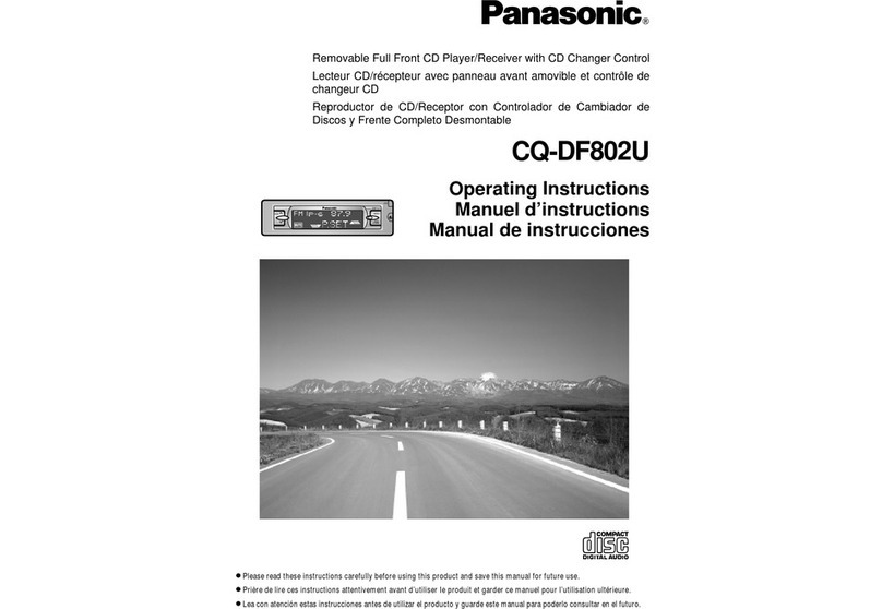
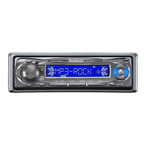
  9. Panasonic CQDF201U - AUTO RADIO/CD DECK User manual

Panasonic CQDF201U - AUTO RADIO/CD DECK User manual

Other manuals for CQDF201U - AUTO RADIO/CD DECK

2

Other Panasonic CD Player manuals

Panasonic SL-S355 User manual

Panasonic

Panasonic SL-S355 User manual

Panasonic SL-SX291C User manual

Panasonic

Panasonic SL-SX291C User manual

Panasonic DVD-LS83E User manual

Panasonic

Panasonic DVD-LS83E User manual

Panasonic CQ-JC179AA User manual

Panasonic

Panasonic CQ-JC179AA User manual

Panasonic SL-S262 User manual

Panasonic

Panasonic SL-S262 User manual
Panasonic SL-PD1349 User manual

Panasonic

Panasonic SL-PD1349 User manual

Panasonic CX-CA1090L User manual

Panasonic

Panasonic CX-CA1090L User manual

Panasonic SL-S262 User manual

Panasonic

Panasonic SL-S262 User manual

Panasonic SL-CT800 User manual

Panasonic

Panasonic SL-CT800 User manual

Panasonic SL-S202 User manual

Panasonic

Panasonic SL-S202 User manual

Panasonic LX-200U User manual

Panasonic

Panasonic LX-200U User manual

Panasonic SL-SX277J User manual

Panasonic

Panasonic SL-SX277J User manual

Panasonic SL-SX425 User manual

Panasonic

Panasonic SL-SX425 User manual

Panasonic SL-SV600J User manual

Panasonic

Panasonic SL-SV600J User manual

Panasonic CQ5301U - AUTO RADIO/CD TRUCK User manual

Panasonic

Panasonic CQ5301U - AUTO RADIO/CD TRUCK User manual

Panasonic RXDS27 - RADIO CASSETTE W/CD User manual

Panasonic

Panasonic RXDS27 - RADIO CASSETTE W/CD User manual

Panasonic SL-J905 User manual

Panasonic

Panasonic SL-J905 User manual
Panasonic WJ-NX200K Operating manual

Panasonic

Panasonic WJ-NX200K Operating manual

Panasonic SLSX420 - PORT. CD PLAYER-LOW User manual

Panasonic

Panasonic SLSX420 - PORT. CD PLAYER-LOW User manual

Panasonic CX-DP801EUC User manual

Panasonic

Panasonic CX-DP801EUC User manual

Panasonic SL-SX500 User manual

Panasonic

Panasonic SL-SX500 User manual

Panasonic CQ-C1001NW User manual

Panasonic

Panasonic CQ-C1001NW User manual

Panasonic CQC1121U - AUTO RADIO/CD DECK User manual

Panasonic

Panasonic CQC1121U - AUTO RADIO/CD DECK User manual

Panasonic KXL-D720 User manual

Panasonic

Panasonic KXL-D720 User manual

Popular CD Player manuals by other brands

Arcam CD23 Handbook

Arcam

Arcam CD23 Handbook

Sanyo MCD-Z1F Service manual

Sanyo

Sanyo MCD-Z1F Service manual

JVC RC-ST3SL instructions

JVC

JVC RC-ST3SL instructions

Technics SL-P9066 operating instructions

Technics

Technics SL-P9066 operating instructions

Marantz HD-CD1 quick start guide

Marantz

Marantz HD-CD1 quick start guide

Sony DVP-FX850 Service manual

Sony

Sony DVP-FX850 Service manual

Philips AZ1140 Instrukcja obs?ugi

Philips

Philips AZ1140 Instrukcja obs?ugi

Alpine 7909 owner's manual

Alpine

Alpine 7909 owner's manual

JVC CH-X350 instructions

JVC

JVC CH-X350 instructions

RCA RP-7923 instruction manual

RCA

RCA RP-7923 instruction manual

Pioneer DEH-P3550MP XM Operation manual

Pioneer

Pioneer DEH-P3550MP XM Operation manual

Philips Shockproof AX2102 brochure

Philips

Philips Shockproof AX2102 brochure

Philips CD582 user manual

Philips

Philips CD582 user manual

Philips AZ 6821 operating manual

Philips

Philips AZ 6821 operating manual

Lasonic MSU-2020 user manual

Lasonic

Lasonic MSU-2020 user manual

Denon DCD-1420 Service manual

Denon

Denon DCD-1420 Service manual

Onkyo DX-7210 instruction manual

Onkyo

Onkyo DX-7210 instruction manual

Cambridge Audio SONATA CD30 manual 

Cambridge Audio

Cambridge Audio SONATA CD30 manual 

manuals.online logo
manuals.online logoBrands
  • About & Mission
  • Contact us
  • Privacy Policy
  • Terms and Conditions

Copyright 2025 Manuals.Online. All Rights Reserved.

ORDER No. ACED001217C1
C4
AUTOMOTIVE CONSUMER ELECTRONICS
CQ-DF201U
Removable Full Front High-Power CD Player / Receiver
SPECIFICATIONS
Specification
1
General
Power Supply DC 12V (11V - 16V),
Test Voltage 14.4V
Negative Ground
Tone Adjustment Range Bass ; ±12dB at 100Hz
Treble ; ±12dB at 10kHz
Current Consumption Less than 2.2A (CD play mode ;
0.5W×4)
Maximum Power Output 45W×4ch (at 400Hz, Vol. MAX)
Pre-Amp Output Voltage 2.0V (CD play mode ; 1kHz 0dB)
Output Impedance 200
Suitable Speaker Impedance 4-8
AM Radio
Frequency Range 530 - 1,710kHz
Usable Sensitivity 28dB/ V (25 V, S/N 20dB)
FM Stereo Radio
Frequency Range 87.9 - 107.9MHz
Usable Sensitivity 11.0dBf. (12.5 V, 75 )
CD Player
Sampling Frequency 32 times oversampling
Pick-Up Type Astigma 3-beam
Light Source Semiconductor Laser
Wavelength 780nm
Frequency Response 20Hz to 20,000Hz (±1dB)
Signal to Noise Ratio 96dB
Wow and Flutter Below measurable limits
Channel Separation 75dB
Dimensions** 7"×1-15/16"×5-7/8"
(178×50×150mm)
Weight** 3lbs 1oz (1.4kg)
* Specifications and the design are subject to possible
modification without notice due to improvements.
** Dimensions and Weight shown are approximate.
-Above specifications comply with EIA standards.
2
1. FEATUERS
- 32bit-times over sampling MASH 1bit 4-DAC system.
- Digital servo for reliable playback.
- PLL (Phase Locked Loop) synthesized tuning.
- 18-FM, 6-AM presets with preset scan
2. REPLACING THE FUSE
Use fuses of the same specified rating (15amps). Using different substitutes or fuses with higher
ratings, or connecting the product directly without a fuse, could cause fire or damage to the stereo
unit.
3. MAINTENANCE
Your product is designed and manufactured to ensure a minimum of maintenance. Use a soft cloth for
routine exterior cleaning. Never use benzine, thinner or other solvents.
4. NOTES
[RADIO BLOCK]
Do not align the AM/FM package block. When the package block is necessary, it will be supplied
already aligned at the factory.
[CD DECK BLOCK]
This model has no servo alignment points because microcomputer controls the servo circuit.
5. DIMENSIONS
6. WIRING CONNECTION
3
7. BLOCK DIAGRAM
4
5
8. TERMINALS DESCRIPTION
8.1. Main Block
IC601 : C2ABGF000018
Pin
No.
Port Description I/O (V)
1 XIN Crystal oscillator - 1.9
2 TEST2 (Connecting to ground) - 0
3 VREG Voltage regulator
capacitor
- 0
4 VSS Ground - 0
5 CHC
DATA
Not used - -
6 N.C. No connection - -
7CHC CK Not used - -
8RM DATA Not used - -
9-12 N.C. No connection - -
13 /LCD CE LCD chip enable O 0.6
14,15 N.C. No connection - -
16 LCD DI LCD data O 4.6
17 LCD CLK LCD clock O 4.7
18 N.C. No connection - -
19 BATT Battery detection I 5.0
20 LCD DO LCD data I 4.9
21 l2C CLK Electric volume cont.
clock
O 5.2
22 l2C DATA Electric volume cont. data I/O 5.2
23 /LED Security LED control O 3.7
24 N.C. No connection - -
25 /EJ ILL Eject illumi. Control O 5.0
26 /ILL Illumi. Control O 5.0
27 N.C. No connection - -
28 /P. LED Panel LED control O 0.4
29 FP
CLOSE
Front panel close SW I 5.2
30 PANEL Panel detection SW I 5.2
31 /EJ Eject SW I 4.7
32-
38
N.C. (Connecting to VDD) - 5.0
39 VDD +5V power supply - 5.0
40 VSS Ground - 0
41-
48
N.C. (Connecting to ground) - 0
49 CD CNT CD power control O 4.9
50 INV CNT Invertor control O 4.9
6
51 DIM 2 Not used - -
52 DIM 1 Dimmer control O4.9
53 PWR CNT Power control O 4.9
54 /MUTE Mute control O 5.0
55 CD DATA CD data I/O 4.7
56 CD CLK1 CD clock O 5.0
57-
61
N.C. No connection - -
62 SUB80/
120
Not used - -
63 SUB CLK Not used - -
64 SUB
DATA
Not used - -
65 /HDB Not used - -
66 N.C. No connection - -
67 /CD RST CD reset O 5.0
68 /CD ON CD power on O 0
69 CD CLK2 CD clock O 4.9
70 CD MUTE CD mute I 0
71 REM IN Remocon data I 5.1
72 CHC STB CD changer strobe O 0
73 /TUNER Tunner power control O 0.3
74 FM FM power control O 0.2
75 /MONO Mono/Stereo selection O 8.0
76 SSC Search stop clear O 0.2
77 ACC SEN ACC detection I 3.9
78 N.C. (Connecting to ground) - 0
79 INIT A Initial value I 0
80 INIT B Initial value I0
81 ADC VSS ADC ground - 0
82 LV L Lch level detection I 1.4
83 LV R Rch level detection I 1.4
84 N.C. (Connecting to ground) -0
85 SD B/S detection I 0.6
86 /RESET (Connecting to VDD) - 5.0
87 HOLD (Connecting to VDD) - 5.0
88 SNS (Connecting to VDD) - 5.0
89 LCTR (Connecting to ground) - 0
90 IFC Radio IF control O 2.6
91 E03 Not used - -
92 /ST FM stereo detection I 4.5
93 PLL VDD +5V power supply - 5.0
94 AM IN (Connecting to ground) - 0
95 OSC Radio oscillator I 2.4
96 PLL VSS PLL ground - 0
7
97 E02 Not used - -
98 E01 PLL phase-comp. error O 1.4
99 TEST 1 (Connecting to ground) - 0
100 XOUT Crystal oscillator - 2.6
8.2. Display Block
IC901 : YEAMLC75854T
Pin
No.
Port Description I/O (V)
1-39 S1-39 LCD segment data O 2.5
40-
43
COM1-4 LCD common O 2.5
44,45 KS1, 2 Not used --
46-
49
KS3-6 Key strobe O 0.9
50-
54
Kl1-5 Key data I 0
55 TEST (Connecting to ground) -0
56 VDD +5V power supply - 5.1
57 VDD1 VDD1 filter terminal - 3.3
58 VDD2 VDD2 filter terminal - 1.7
59 VSS Ground - 0
60 OSC Oscillator terminal - 3.9
61 DO Key data output O4.4
62 CE LCD driver chip enable I 0
63 CLK LCD clock I 0
64 DI LCD data I 0
8.3. CD Servo Block
IC2 : MN6627481RPM
8
Pin
No.
Port Description I/O (V)
1 BCLK Bit clock output O 2.5
2 LRCK L/R select output O 2.5
3 SRDATA Serial data output O 2.5
4 DVDD1 +5V digital power supply - 5.1
5 DVSS1 Digital ground - 0
6 TX Not used - -
7 MCLK MPU command clock I 4.6
8 MDATA MPU command data I 0.2
9 MLD MPU command load I 4.8
10 SENSE Not used - -
11 /FLOCK Not used - -
12 /TLOCK Not used - -
13 BLKCK Sub-code block clock O 0
14 SQCK Q code external clock I 0
15 SUBQ Q code output O 5.1
16 DMUTE Mute input I 2.9
17 STAT Status output O 0
18 /RST Reset input I 5.0
19 SMCK Not used - -
20 PMCK Not used - -
21 TRV Forced traverse output - 2.5
22 TVD Traverse drive output O 2.5
23 PC Not used - -
24 ECM Spindle motor drive O 2.4
25 ECS Spindle motor drive O 2.5
26 KICK Kick pulse output O 2.4
27 TRD Tracking drive O 2.5
28 FOD Focus drive O 2.6
29 VREF D/A reference voltage I 2.5
30 FBAL Focus balance adjust O 2.5
31 TBAL Tracking balance adjust O 2.5
32 FE Focus error signal I 2.5
33 TE Tracking error signal I 2.5
34 RFENV RF envelope signal I 2.5
35 VDET Vibration detection I 0
36 OFT Off track signal I 0
37 TRCRS Track closs signal I 2.7
38 /RFDET RF detection signal I 0
39 BDO Drop out signal I 0
40 LDON Laser on/off control O 5.0
41 PLL F2 Not used --
42 TOFS Not used - -
43 WVEL Not used - -
9
43
WVEL
Not
used
44 ARE RF signal I 2.5
45 IREF Reference current input I 1.2
46 DRF Connecting to ground - 0
47 DSLF DSL loop filter I/O 2.5
48 PLLF PLL loop filter I/O 2.3
49 VCOF Connecting to VDD - 5.1
50 AVDD2 +5V analog power supply - 5.1
51 AVSS2 Analog ground - 0
52-
55
Not used - -
56 SBCK (Connecting to ground) - 0
57 VSS Ground - 0
58 X1 Crystal oscillator - 2.5
59 X2 Crystal oscillator - 2.9
60 VDD +5V power supply - 5.1
61-
69
Not used - -
70 IOSEL (Connecting to ground) - 0
71 /TEST Connecting to VDD - 5.1
72 AVDD1 +5V analog power supply - 4.8
73 OUTL Audio Lch output O 2.4
74 AVSS1 Analog ground - 0
75 OUTR Audio Rch output O 2.4
76 RSEL connecting to VDD I 5.1
77 CSEL Connecting to ground - 0
78 PSEL Serial data input I 2.5
79 MSEL L/R select input I 2.5
80 SSEL Bit clock input I 2.5
IC4 : C2BBD000218
10