Panasonic et-jpc100bu User manual

DPQX1104ZA
Model No. ET-JPC100BU
ET-JPC100WU
Installation Instructions
Ceiling Kit
Thank you for purchasing this Panasonic product.
■To customers
This manual is intended for use by installation personnel. Be sure to employ certified personnel to perform the installation.
After installation, have the installation personnel return this manual to you, and save it for future use.
When moving or removing the projector, give this manual to the certified personnel and have them perform the procedure.
■To installation personnel
Read the instructions thoroughly and then perform the instaration correctly and safely.
Be sure to read through the section entitled “Read this first!” (pages 2 to 3) before proceeding with the installation.
After installation, return this manual to the customer.
* Above illustration is shown in combination of this product and optional projector.
ENGLISH
ENGLISH
FRANÇAIS
ESPAÑOL
ET-JPC100BWU(DPQX1104ZA)E.indd1ET-JPC100BWU(DPQX1104ZA)E.indd1 2016/06/0813:50:552016/06/0813:50:55

2 - ENGLISH
Read this first!
WARNING: THIS APPARATUS MUST BE EARTHED.
Proper grounding is required to ensure personal safety.
WARNING
Ask a qualified technician or your dealer to perform the installation work.
Inadequate installation may result in fire, electric shocks, or falling of the projector.
Follow the instructions specified in “Installation” of this manual, and perform secure installation.
To be installed by qualified personnel only.
Do installation in accordance with your country regulations.
Before performing the installation work, be sure to shut off the power supply of the indoor wiring.
Failing to do so may cause a fire or electric shock.
Install the certified wiring circuit breaker (breaker with rated current of 20 A or less) in a location that
can be easily reached.
Insufficient capacity of the indoor wiring for the power supply or incorrect installation may result in a fire or elec-
tric shock.
If anything abnormal occurs, immediately shut off the power supply of the indoor wiring with the certified
wiring circuit breaker.
To prevent wiring damage or abrasion, do not expose wires to the edge of sheet metal or any other
sharp objects.
Failing to do so may cause a fire or electric shock.
Do not connect electrical wiring via this product.
Doing so may cause a fire.
Make sure that your footing is safe and secure during installation.
If your footing is not secure, you may fall down or drop the projector, and an injury may result.
Install the product in a way that is suitable for the structure and material of the installation location.
Performing the installation work in an incorrect way may cause a fire, electric shock, or falling accident.
Do not mount the product to a ceiling that is unable to withstand the weight.
Doing so may cause injury due to falling or a fire or electric shock.
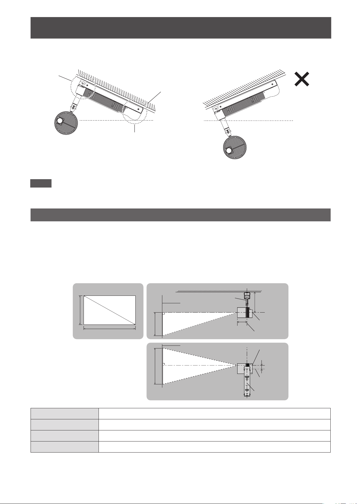
Do not install the product in a location where the intake and exhaust of the projector will be blocked.
Heat accumulating inside the projector may cause a fire.
Do not set up the projector in humid or dusty places or in places where the projector may come into
contact with oily smoke or steam.
Using the projector under such conditions will result in fire, electric shocks or deterioration of components.
Deterioration of components may cause the projector which is mounted on the ceiling to fall down.
Do not install other than a specified projector.
Do not install a projector in a way other than specified.
Doing so may cause a failing accident or a fire or electric shock.
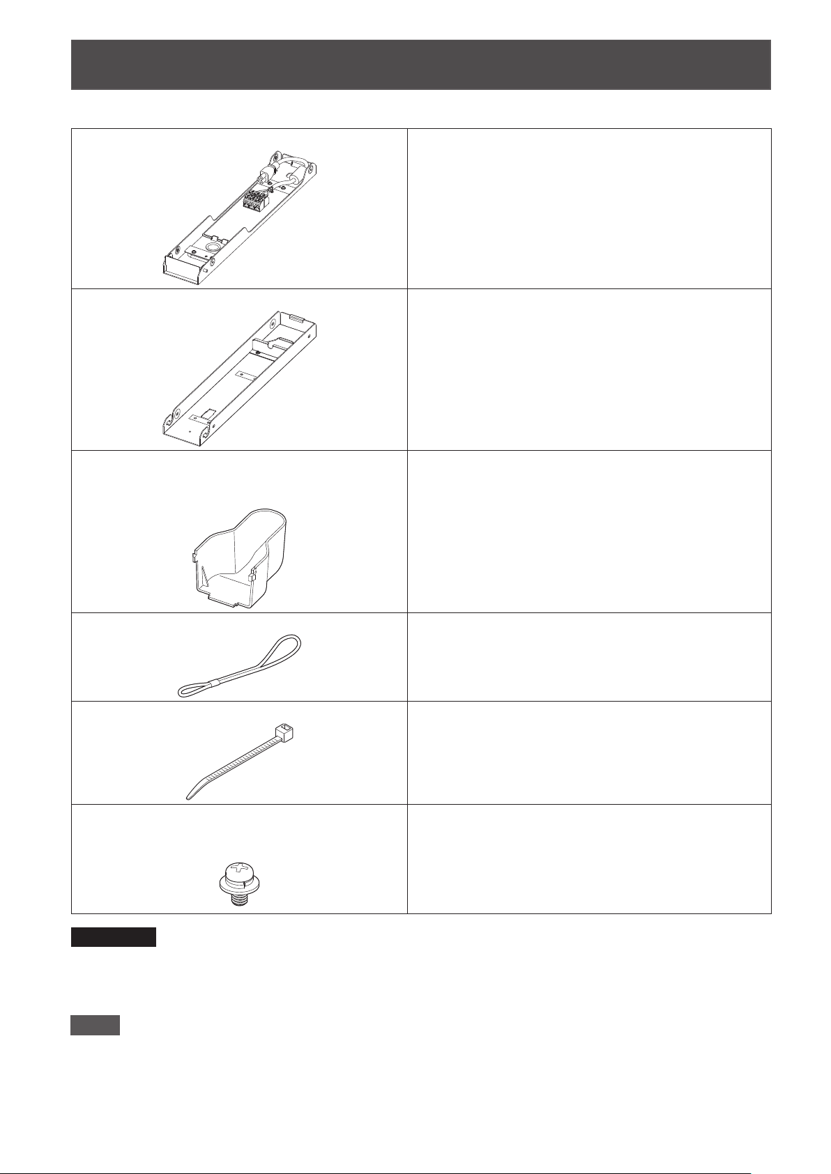
Be sure to use the supplied parts that make up this product when installing the product.
Insufficient strength or improper installation may cause injury due to falling or a fire or electric shock.
Do not dismantle or modify this product.
Doing so may cause it to break or injury due to falling.
Do not do anything that might damage the power cord.
If the power cord is used while damaged, electric shocks, short-circuits or fire will result.
Do not damage the power cord, make any modifications to it, place it near any hot objects, bend it
excessively, twist it, pull it, place heavy objects on top of it or wrap it into a bundle.
Completely insert the power connector into the projector terminal.
If the power connector is not inserted correctly, electric shocks or overheating will result.
Do not allow children to reach the supplied screws and the string.
Accidentally swallowing them can cause physical harm.
If swallowed, seek medical advice immediately.
ET-JPC100BWU(DPQX1104ZA)E.indd2ET-JPC100BWU(DPQX1104ZA)E.indd2 2016/06/0813:50:552016/06/0813:50:55

ENGLISH - 3
Read this first! (continued)
CAUTION
Do not install this product in a location where salt damage occurs or corrosive gas is generated.
Doing so may may cause falling due to corrosion.
Do not use the projector together with dimmers such as a light controller.
Doing so will result in the damage to the components inside the projector and will cause fire.
Do not put excessive force on the projector by hanging on the projector or dangling any object.
Doing so will result in falling of the projector and injuries.
Mount this product in the specified orientation to a flat ceiling or a ceiling with a slope of up to 45°.
Mounting this product to an inappropriate surface such as to a wall, floor, or ceiling with a steep slope or
mounting it in the wrong orientation may cause a falling accident.
Install the ceiling mount screws and bolts so that they do not touch any metal inside the ceiling.
If they touch metal inside the ceiling, a fire or electric shock may result.
When disconnecting the power cord, be sure to hold the power connector.
If the power cord itself is pulled, the lead will become damaged, and fire, short-circuits or serious electric
shocks will result.
Panasonic disclaims all liability for any accidents or any damage caused by the installation
of the ceiling mount bracket using methods that are not described in these Installation
Instructions or methods that do not use the parts specified in these Instructions.
If products are no longer being used, they should be dismantled and removed by the
certified personnel as soon as possible.
ET-JPC100BWU(DPQX1104ZA)E.indd3ET-JPC100BWU(DPQX1104ZA)E.indd3 2016/06/0813:50:552016/06/0813:50:55

4 - ENGLISH
Contents
Read this first! ................................................................................................... 2
Installation precautions .................................................................................... 5
Product composition......................................................................................... 6
Before installation ............................................................................................. 7
Items to prepare ................................................................................................................. 7
Names of parts ................................................................................................................... 8
Installation orientation......................................................................................................... 9
Installation position ........................................................................................................... 10
Installation........................................................................................................ 13
Main procedures............................................................................................................... 13
Preparing the adapter cover ............................................................................................. 13
Mounting the ceiling mount bracket to the ceiling............................................................. 13
Connecting the indoor wiring for the power supply .......................................................... 17
Changing the orientation of the main unit of the projector................................................ 18
Mounting the projector mount bracket to the projector..................................................... 19
Mounting the projector to the ceiling mount bracket......................................................... 21
Connecting the power cord to the projector...................................................................... 23
Adjusting the projection position....................................................................................... 25
Specifications .................................................................................................. 27
External dimension diagram ............................................................................................. 27
Assembly dimension diagram........................................................................................... 27
ET-JPC100BWU(DPQX1104ZA)E.indd4ET-JPC100BWU(DPQX1104ZA)E.indd4 2016/06/0813:50:552016/06/0813:50:55

ENGLISH - 5
Installation precautions
Install this product in a place that is strong enough to withstand the weight of both the projector and
product.
Install this product in a place where the intake and exhaust of the projector will not be blocked.
Do not install this product in a place near the sea or where corrosive gas is generated.
Do not install this product in places subject to sudden temperature changes, such as near an air con-
ditioner air outlet or lighting equipment (studio lamps, etc.).
Before performing the work, be sure to shut off the power supply to the room by, for example, turning
off the wiring circuit breaker.
This product must be installed in accordance with the applicable installation code by a qualified per-
sonnel, familiar with the construction and operation of the product and hazards involved.
Single copper wires with an AWG12 to AWG14 can be used (are supported) for the indoor wires that
connect to the terminal block of the ceiling mount bracket.
If wallpaper is affixed to the surface where the product will be mounted to the ceiling, make sure the
wallpaper paste is sufficiently dry before installing this product.
Failing to do so may result in rusting or discoloration of the paint.
The inrush current for the projectors supported by this product is 80 A.
Give consideration to the specifications of any wiring equipment that will be connected, including the wiring
circuit breaker and switches, before carrying out the wiring work.
With the exception of wood screws, use the following tightening torques for the screws and bolts.
Size Tightening torque
M4 1.2 ±0.3 N•m
M10 20 ±1 N•m
When tightening screws or bolts, use a torque driver or torque wrench. Do not use electrical drivers
or impact drivers.
ET-JPC100BWU(DPQX1104ZA)E.indd5ET-JPC100BWU(DPQX1104ZA)E.indd5 2016/06/0813:50:552016/06/0813:50:55

6 - ENGLISH
Product composition
Check that the package contains the following parts. The number enclosed in < > is the quantity.
Ceiling mount bracket <1> This ceiling mount bracket is mounted to the ceiling to
support the entire product.
It has a terminal block for connecting the indoor wiring
for the power supply, and a power cord that is connected
to the projector to supply it with power.
Projector mount bracket <1> This projector mount bracket is mounted to the projector
and then attached to the ceiling mount bracket.
Adapter cover <1>
(ET-JPC100BU: TKFE28802)
(ET-JPC100WU: TKFE28801)
This adapter cover hides the <AC IN> socket part of the
projector.
String (6103430249) <1> This is to prevent the adapter cover from dropping.
Fixer cable tie (TMME244) <1> This is used for fix the indoor wiring for the power supply
to the ceiling mount bracket so as to stop tension being
applied.
Screw, captive washer (M4 x 8) <8>
(ET-JPC100BU: XYN4+F8FJK)
(ET-JPC100WU: 4112055002)
These are used for the mounting and attaching of the
brackets.
Attention
After removing the product from the package, dispose of the packing material appropriately.
If any part is missing, contact the dealer.
Store small parts appropriately in a place out of the reach of infants and small children.
Note
Please note that an assembly test has been performed using all parts so this product may have screw
tightening marks around the parts where the ceiling mount bracket and projector mount bracket fit together.
The product composition, projector, combination of the product and projector, etc. shown in the illustrations may
differ from the actual equipment.
ET-JPC100BWU(DPQX1104ZA)E.indd6ET-JPC100BWU(DPQX1104ZA)E.indd6 2016/06/0813:50:552016/06/0813:50:55

ENGLISH - 7
Before installation
Items to prepare
The items that you need to provide in advance in addition to the supplied parts to mount this product to a ceiling
are as follows.
This product is a bracket for mounting the projector (separately sold product) to a ceiling.
Use it mounted to a compatible projector.
Compatible projectors: PT-JW130FBU / PT-JW130FWU
The following parts are required when mounting the ceiling mount bracket to the ceiling.
Obtain commercially available parts suitable for the structure of the ceiling and installation
method.
The number enclosed in < > is the quantity.
Structure of mounting area Commercially available parts
When concrete beams or similar
(Bolt diameter: M10)
Ceiling mount bolt <2>
Hexagonal nut <6>
Flat washer <6>
Spring washer <4>
Anchor nut or curled plug <2>
When wooden beams or similar
(Bolt diameter: M10)
Ceiling mount bolt <2>
Hexagonal nut <8>
Flat washer <8>
Spring washer <4>
When ceiling surface with wood reinforcement
members
Ensure there will be thread engagement of at least 16 mm
(5/8") in the ceiling reinforcement member; wood screw with
nominal diameter of 3.1 mm (1/8") <4>
Note
When moving this product to another place, you will need a fixer cable tie (total length: 80 mm [3-5/32"], UL
flame-retardant grade: UL94-V2) equivalent to the supplied one.
A work bench and a soft cloth to prevent scratches are required when mounting the projector
mount bracket to a projector.
Prepare a bench for the mounting work with a height of at least 280 mm (11") and lay a soft cloth or the like
below the projector to prevent scratches.
ET-JPC100BWU(DPQX1104ZA)E.indd7ET-JPC100BWU(DPQX1104ZA)E.indd7 2016/06/0813:50:562016/06/0813:50:56

8 - ENGLISH
Before installation (continued)
Names of parts
Ceiling mount bracket
Power connector
Power cord
Terminal block
Indoor wiring hole
Shaft
Ceiling mount bolt hole
Fixer cable tie attachment holes
Projector mount bracket
Power cord hole
Hook parts
ET-JPC100BWU(DPQX1104ZA)E.indd8ET-JPC100BWU(DPQX1104ZA)E.indd8 2016/06/0813:50:562016/06/0813:50:56

ENGLISH - 9
Before installation (continued)
Installation orientation
Mount this product in the specified orientation to a flat ceiling or a ceiling with a slope of up to 45°. Mounting this
product to an inappropriate surface such as to a wall or floor or mounting it to a ceiling with a steep slope or in the
wrong orientation may cause a fall or drop accident.
■Do not install the projector on a sloped ceiling exceeding 45°, wall, or
floor.
0 to maximum 45°
Ceiling
Exceeding 45°
Ceiling
Can be installed Cannot be installed
Wall
Floor
Cannot be installed Cannot be installed
■Do not install the projector on a ceiling tilted right or left.
Can be installed Cannot be installed Cannot be installed
Ceiling
Power supply
unit
ET-JPC100BWU(DPQX1104ZA)E.indd9ET-JPC100BWU(DPQX1104ZA)E.indd9 2016/06/0813:50:562016/06/0813:50:56

10 - ENGLISH
Before installation (continued)
■When mounting this product to the ceiling, mount it so that the shaft side
of the ceiling mount bracket is higher than the power supply cord side.
Shaft side
Power cord side
Ceiling
Can be installed Cannot be installed
Note
The product, the projector, the product and projector used in a combined state, and other parts shown in the
illustrations in this manual may differ from the actual equipment.
Installation position
Decide the installation position on the ceiling while referring to “Projection related dimension diagrams,” “Projection
distances,” and “Mounting hole dimensions.”
The following illustrations are examples of the projection lens surface of the main unit of the projector and the
projection surface positioned so that they are facing each other straight. The projection position and projection
screen size can be adjusted on the projector side in accordance with the projection surface position and range.
Projection related dimension diagrams
SD
L (LW/LT)
L (LW/LT)
SW SH
SH
SW
300.8
mm
(11-27/32")
42.6
mm
(1-11/16")
142.0
mm
(5-19/32")
Ceiling
Pole
lens center
lens center
pole center
pole center
pole center
Projection surface
Projection surface
Projected image
L (LW/LT)*1 Projection distance (distance from projection lens surface to the projection surface) (m)
SH Image height (m)
SW Image width (m)
SD Screen diagonal size (m)
*1 LW: Minimum projection distance
LT: Maximum projection distance
ET-JPC100BWU(DPQX1104ZA)E.indd10ET-JPC100BWU(DPQX1104ZA)E.indd10 2016/06/0813:50:562016/06/0813:50:56

ENGLISH - 11
Before installation (continued)
Projection distance (when aspect ratio 16:10)
The following shows the dimensional relationship between the projector and projection surface.
The dimensions included in the following table have a slight error. Also, when keystone correction is performed
on the projector side, correction is made so that the projected image size becomes smaller than the specified
screen size.
(Unit: m)
Projected image size Projection distance (L)
Diagonal (SD) Height (SH) Width (SW) Min. (LW) Max. (LT)
0.76 (30") 0.404 0.646 0.95 2.10
1.02 (40") 0.538 0.862 1.28 2.81
1.27 (50") 0.673 1.077 1.61 3.52
1.52 (60") 0.808 1.292 1.94 4.23
1.78 (70") 0.942 1.508 2.27 4.94
2.03 (80") 1.077 1.723 2.60 5.65
2.29 (90") 1.212 1.939 2.93 6.36
2.54 (100") 1.346 2.154 3.26 7.07
3.05 (120") 1.615 2.585 3.92 8.50
3.81 (150") 2.019 3.231 4.91 10.63
5.08 (200") 2.692 4.308 6.55 14.19
Projection distance formula (when aspect ratio 16:10)
To use an image size not listed in this manual, check the projected image size SD (m) and use the respective
formula to calculate projection distance (L).
The unit of the formula is all “m”. (Value obtained by the following calculation formula contains a slight error.)
When calculating a projection distance using image size designation (value in inches), multiply the value in
inches by 0.0254 and substitute it into SD in the formula for calculating the projection distance.
Minimum projection
distance (LW) L = 1.2976 × SD - 0.0385
Maximum projection
distance (LT) L = 2.7999 × SD - 0.0379
Mounting hole dimensions
<Ceiling mount bracket diagram>
Unit: mm
370 (14-9/16")
360 (14-3/16")
436 (17-5/32")
77.5 (3-1/16")
41.5
(1-5/8")
31.5
(1-1/4")
5 (3/16")
78 (3-1/16")
39
(1-17/32")
4-Φ3.8
R6
Φ14
Φ12
ET-JPC100BWU(DPQX1104ZA)E.indd11ET-JPC100BWU(DPQX1104ZA)E.indd11 2016/06/0813:50:562016/06/0813:50:56

12 - ENGLISH
Before installation (continued)
<Ceiling hole positions dimensions>
Unit: mm
360 (14-3/16")
60 (2-3/8")
30
(1-3/16")
77.5 (3-1/16")
370 (14-9/16")
87.5 (3-7/16")
Hole for indoor wiring
M10 bolt hole
(for ceiling mount bolt)
M10 bolt hole
(for ceiling mount bolt)
Wood screw installation
position (×4)
Wood screw installation position (×4)
Projector pole
center position
ET-JPC100BWU(DPQX1104ZA)E.indd12ET-JPC100BWU(DPQX1104ZA)E.indd12 2016/06/0813:50:562016/06/0813:50:56

ENGLISH - 13
Installation
Main procedures
The main procedures for using this product to install a projector (separately sold product) on a ceiling are as fol-
lows.
Before performing the work, be sure to shut off the power supply to the room by, for example, turning off the wir-
ing circuit breaker.
1) Preparing the adapter cover (13 page)
2) Mounting the ceiling mount bracket to the ceiling (13 page)
3) Connecting the indoor wiring for the power supply (17 page)
4) Changing the orientation of the main unit of the projector (18 page)
5) Mounting the projector mount bracket to the projector (19 page)
6) Mounting the projector to the ceiling mount bracket (21 page)
7) Connecting the power cord to the projector (23 page)
8) Adjusting the projection position (25 page)
Preparing the adapter cover
String attachment hole
1) Attach the string to the adapter cover.
Pass the end of the string (end with the small loop)
through the hole in the adapter cover and then
attach the string to the adapter cover as shown in
the following diagram.
Mounting the ceiling mount bracket to the ceiling
Check the height, space, and structure of the installation location and then determine the installation position on
the ceiling in advance while referring to “Installation position” (10 page). Use the center of the projector pole as a
guide for positioning.
The mounting method for the ceiling mount bracket differs depending on the structure of the ceiling. Install it in a
way that is appropriate for the ceiling to which it is to be mounted.
Check that the installation location of the ceiling mount bolts and ceiling kit is strong enough to withstand the
weight of both the projector and ceiling kit.
Attention
When mounting the product to the ceiling with ceiling mount bolts, be sure to use commercially available
ceiling mount bolts, hexagonal nuts, flat washers, spring washers, and anchor nuts or curled plugs for the
M10 thread size.
When mounting the product to a concrete ceiling with ceiling mount bolts, drill anchor nut or curled plug
mounting holes to match the size specified by the manufacturer.
Securely tighten each nut, and if necessary take a measure such as using two nuts
or thread-locking fluid to prevent loosening.
When mounting the product to a ceiling with wood screws, ensure there will be
thread engagement of at least 16 mm (5/8") in the ceiling reinforcement member and
purchase wood screws with a nominal diameter of 3.1 mm (1/8"). Two nuts
ET-JPC100BWU(DPQX1104ZA)E.indd13ET-JPC100BWU(DPQX1104ZA)E.indd13 2016/06/0813:50:562016/06/0813:50:56

14 - ENGLISH
Installation (continued)
When the ceiling mount bolt installation location is concrete
Anchor nut or
curled plug
Flat washer Hexagonal nut
Hexagonal nut
Ceiling mount bolt
Hexagonal nut
Hexagonal nut
Ceiling mount bolt
Flat washer
Spring washer
Spring washer
Flat washer
Flat washer
Spring washer
Spring washer
Indoor wiring hole (bracket side) Terminal
block
Ceiling mount bracket
Protrudes 20 mm (25/32") to 30 mm (1-3/16")*1
from the ceiling surface.
Ceiling board
Anchor nut or
curled plug
Concrete
*1 27 mm (1-1/16") to 30 mm (1-3/16") when two nuts
Hole for indoor wiring
1) Drill mounting holes in reference to “Mounting hole dimensions” (11 page).
Drill anchor nut or curled plug mounting holes to match the size specified by the manufacturer.
Drill two holes in the ceiling board for passing the ceiling mount bolts (M10) through and one hole in the
ceiling board for pulling the indoor wiring through.
2) Attach the two ceiling mount bolts to the concrete ceiling.
Attach the anchor nuts or curled plugs to the concrete ceiling and securely fix the two ceiling mount bolts.
When installing anchor nuts or curled plugs, strictly adhere to the installation instructions supplied by the
manufacturer so that they will not come out or loosen, or be dislodged from the intended positions.
If the ceiling concrete has become weak and fragile or may have degraded as a result of being old,
reinforce it with iron or wood.
3) Pull out the indoor wiring for the power supply from the ceiling.
Pull out the indoor wiring for the power supply from the indoor wiring hole you drilled in the ceiling board.
4) Attach the ceiling mount bracket to the ceiling mount bolts.
Pass the indoor wiring for the power supply through the indoor wiring hole of the ceiling mount bracket and
then securely fix the ceiling mount bracket to the ceiling mount bolts.
The ends of ceiling mount bolts at the ceiling mount bracket side should protrude by approx. 5 mm (3/16")
from the hexagonal nuts.
Make sure the distance from the surface of the ceiling mount bracket to the end of the ceiling mount bolts
is within 30 mm (1-3/16"). If the distance is too long, the projector mount bracket will not be able to be
attached.
Be sure to use commercially available flat washers and spring washers to install the ceiling mount bracket.
Attention
Tighten the hexagonal nuts fixing the ceiling board and ceiling mount bracket together while considering the
strength of the ceiling board material. If the ceiling board material is of low strength, the ceiling board may
be damaged if the nuts are tightened to the specified torque. Also take a measure such as using two nuts or
thread-locking fluid to prevent loosening of the hexagonal nuts.
ET-JPC100BWU(DPQX1104ZA)E.indd14ET-JPC100BWU(DPQX1104ZA)E.indd14 2016/06/0813:50:562016/06/0813:50:56

ENGLISH - 15
Installation (continued)
When the ceiling mount bolt installation location is a wooden beam
Spring washer
Hexagonal nut
Hexagonal nut
Ceiling mount bolt
Hexagonal nut
Hexagonal nut
Ceiling mount bolt
Flat washer
Spring washer
Flat washer
Spring washer
Indoor wiring hole (bracket side) Terminal
block
Ceiling mount bracket
Protrudes 20 mm (25/32") to 30 mm (1-3/16")*1
from the ceiling surface.
Ceiling board
Beam
Flat washer
Spring washer
Flat washer
*1 27 mm (1-1/16") to 30 mm (1-3/16") when two nuts
Hole for indoor wiring
1) Drill mounting holes in reference to “Mounting hole dimensions” (11 page).
Drill two penetration holes in the ceiling beam for the ceiling mount bolts.
Drill two holes in the ceiling board for passing the ceiling mount bolts (M10) through and one hole in the
ceiling board for pulling the indoor wiring through.
2) Attach the two ceiling mount bolts.
Securely fix the two ceiling mount bolts to the ceiling beam.
If the place for fixing the ceiling mount bolts is not strong enough, sufficiently reinforce it giving
consideration to safety factors.
3) Pull out the indoor wiring for the power supply from the ceiling.
Pull out the indoor wiring for the power supply from the indoor wiring hole you drilled in the ceiling board.
4) Attach the ceiling mount bracket to the ceiling mount bolts.
Pass the indoor wiring for the power supply through the indoor wiring hole of the ceiling mount bracket and
then securely fix the ceiling mount bracket to the ceiling mount bolts.
The ends of ceiling mount bolts at the ceiling mount bracket side should protrude by approx. 5 mm (3/16")
from the hexagonal nuts.
Make sure the distance from the surface of the ceiling mount bracket to the end of the ceiling mount bolts
is within 30 mm (1-3/16"). If the distance is too long, the projector mount bracket will not be able to be
attached.
Be sure to use commercially available flat washers and spring washers to install the ceiling mount bracket.
Attention
Tighten the hexagonal nuts fixing the ceiling board and ceiling mount bracket together while considering the
strength of the ceiling board material. If the ceiling board material is of low strength, the ceiling board may
be damaged if the nuts are tightened to the specified torque. Also take a measure such as using two nuts or
thread-locking fluid to prevent loosening of the hexagonal nuts.
ET-JPC100BWU(DPQX1104ZA)E.indd15ET-JPC100BWU(DPQX1104ZA)E.indd15 2016/06/0813:50:572016/06/0813:50:57

16 - ENGLISH
Installation (continued)
When mounting to a reinforced ceiling with wood screws
Reinforcement
Wood screwWood screw
Ceiling board
Indoor wiring hole (bracket side)
Ceiling mount bracket
Terminal block
Wood screw
installation holes
Wood screw
installation holes
Indoor wiring hole
Hole for indoor wiring
1) Drill mounting holes in reference to “Mounting hole dimensions” (11 page).
Drill one hole in the ceiling board for pulling through the indoor wiring and then mark the four positions for
fixing the bracket in place with the wood screws.
2) Pull out the indoor wiring for the power supply from the ceiling.
Pull out the indoor wiring for the power supply from the indoor wiring hole you drilled in the ceiling board.
3) Mount the ceiling mount bracket to the ceiling.
Pass the indoor wiring for the power supply through the indoor wiring hole of the ceiling mount bracket and
then align the ceiling mount bracket with the predetermined positions and securely fix it to the ceiling board.
Use commercially available wood screws with a nominal diameter of 3.1 mm (1/8") to secure the ceiling
mount bracket.
If the ceiling board of the installation location is not strong enough, the product may fall or the ceiling board
may bend or be damaged, etc. Sufficiently reinforce it giving consideration to safety factors.
When reinforcing the ceiling, ensure there will be thread engagement of at least 16 mm (5/8") in the ceiling
reinforcement member.
[Reference]
Wood screw pullout strength Unit (N)
Tree type
Thickness of at least
20 mm (25/32")
Wood screw (nominal diameter 3.1 mm [1/8"] x thread
engagement 16 mm [5/8"])
Cross grain Straight grain Edge
Pine 637 539 441
Cedar 490 490 343
Cypress 784 1029 441
Lauan 441 -
Plywood 539 392
Laminated veneer
lumber 392 193
ET-JPC100BWU(DPQX1104ZA)E.indd16ET-JPC100BWU(DPQX1104ZA)E.indd16 2016/06/0813:50:572016/06/0813:50:57

ENGLISH - 17
Installation (continued)
Connecting the indoor wiring for the power supply
This section describes connecting the indoor wiring for the power supply to the terminal block of the ceiling mount
bracket.
Single copper wires with an AWG12 to AWG14 are supported for the wiring.
10」11 mm (13/32" - 7/16")
115」126 mm (4-17/32" - 4-31/32")
Single copper wire
Sheath
Insulation
Power cable
1) Strip the coating off the wires.
Pull out the indoor wiring for the power supply
(power cable) from the ceiling, strip 115 mm
(4-17/32") to 126 mm (4-31/32") of the sheath
off the cable, and then strip 10 mm (13/32")
to 11 mm (7/16") of the insulation off the two
power wires and earth wire.
Exceeding the specified dimensions may cause
electric shock.
ⅰⅱ
Release buttons
Neutral terminal
Live terminal
Power wires
Earth wire
Earth terminal
Terminal block
2) Connect the power cable to the terminal block
of the ceiling mount bracket.
First, perform proper grounding in accordance
with your country regulations using the earth
terminal of the terminal block. Insert the earth
wire all the way into the earth terminal ( ) (i).
Improper connection may cause a fire.
Next, insert the two power wires all the way into
the live terminal (L1) and neutral terminal (N) of
the terminal block (ii). Improper connection may
cause a fire.
Attention
Do not connect the power cable of another
projector or lighting via the terminal block of this
product. Doing so may cause a fire.
Note
To disconnect the connected power cable from the
terminal block, pull out each wire while pushing in
the corresponding release button on the terminal
block with a flat-blade screwdriver (with blade edge
width of 6 mm [1/4"] or less and blade tip thickness
of 0.8 mm [1/32"] or less). Disconnect the power
wires first and then disconnect the earth wire last.
Fixer cable tie attachment position
3) Fix the power cable to the ceiling mount
bracket.
Push the power cable connected to the terminal
block back into the ceiling to remove any slack
and then pass the supplied fixer cable tie
through the fixer cable tie attachment holes and
use it to secure the power cable to the ceiling
mount bracket.
Cut off the excess part of the fixer cable tie so
that the fixer cable tie will fit inside when you
attach the projector mount bracket to the ceiling
mount bracket.
ET-JPC100BWU(DPQX1104ZA)E.indd17ET-JPC100BWU(DPQX1104ZA)E.indd17 2016/06/0813:50:572016/06/0813:50:57

18 - ENGLISH
Installation (continued)
Changing the orientation of the main unit of the projector.
This section describes changing the orientation of the main unit of the projector to make the mounting work of the
projector mount bracket easier to do.
Rotating fixing
screw
1) Place the projector on a cloth or the like that
has been laid on a flat surface.
2) Loosen the fixing screw.
Loosen the rotating fixing screw of the projector
with the 7/64” Allen wrench supplied with the
projector.
Shaft holder
Main unit
3) Change the orientation of the main unit.
Loosening the rotating fixing screw enables
rotation of the shaft holder so that the
orientation of the main unit can be changed.
4) Tighten the fixing screw.
Tighten the rotating fixing screw with the 7/64” Allen wrench supplied with the projector to prevent the main
unit moving during the mounting work.
Note
The rotating fixing screw is a hexagon socket head screw (M6). Take care because it will come out of the
projector if loosened too much.
ET-JPC100BWU(DPQX1104ZA)E.indd18ET-JPC100BWU(DPQX1104ZA)E.indd18 2016/06/0813:50:572016/06/0813:50:57

ENGLISH - 19
Installation (continued)
Mounting the projector mount bracket to the projector
This section describes mounting the projector mount bracket to the projector.
Power supply unit
1) Place the projector on the work bench.
Place the power supply unit of the projector on
a work bench that has a soft cloth or the like
laid on it.
Attention
The projector will not be stable so two people
should perform the projector mount bracket
mounting work.
Projector mount bracket
Power supply unit
2) Align the projector mount bracket.
Orient the projector mount bracket at an angle
of 90° to the power supply unit of the projector.
Opening
Protrusion
3) Mount the projector mount bracket to the
projector.
Align the opening in the projector mount
bracket with the position of the protrusion on
the projector.
ET-JPC100BWU(DPQX1104ZA)E.indd19ET-JPC100BWU(DPQX1104ZA)E.indd19 2016/06/0813:50:572016/06/0813:50:57

20 - ENGLISH
Installation (continued)
4) Rotate the projector mount bracket.
Orient the projector mount bracket to match
the orientation of the power supply unit of the
projector.
Power supply unit <AC IN> socket
Power supply unit
5) Slide the projector mount bracket.
Slide the projector mount bracket so that it
attaches to the <AC IN> socket side of the
power supply unit of the projector.
ET-JPC100BWU(DPQX1104ZA)E.indd20ET-JPC100BWU(DPQX1104ZA)E.indd20 2016/06/0813:50:572016/06/0813:50:57
This manual suits for next models
1
Table of contents
Other Panasonic DLP Projector manuals