manuals.online logo
Brands
  1. Home
  2. •
  3. Brands
  4. •
  5. Panasonic
  6. •
  7. Plasma TV
  8. •
  9. Panasonic Viera TX-P42S20L User manual

Panasonic Viera TX-P42S20L User manual

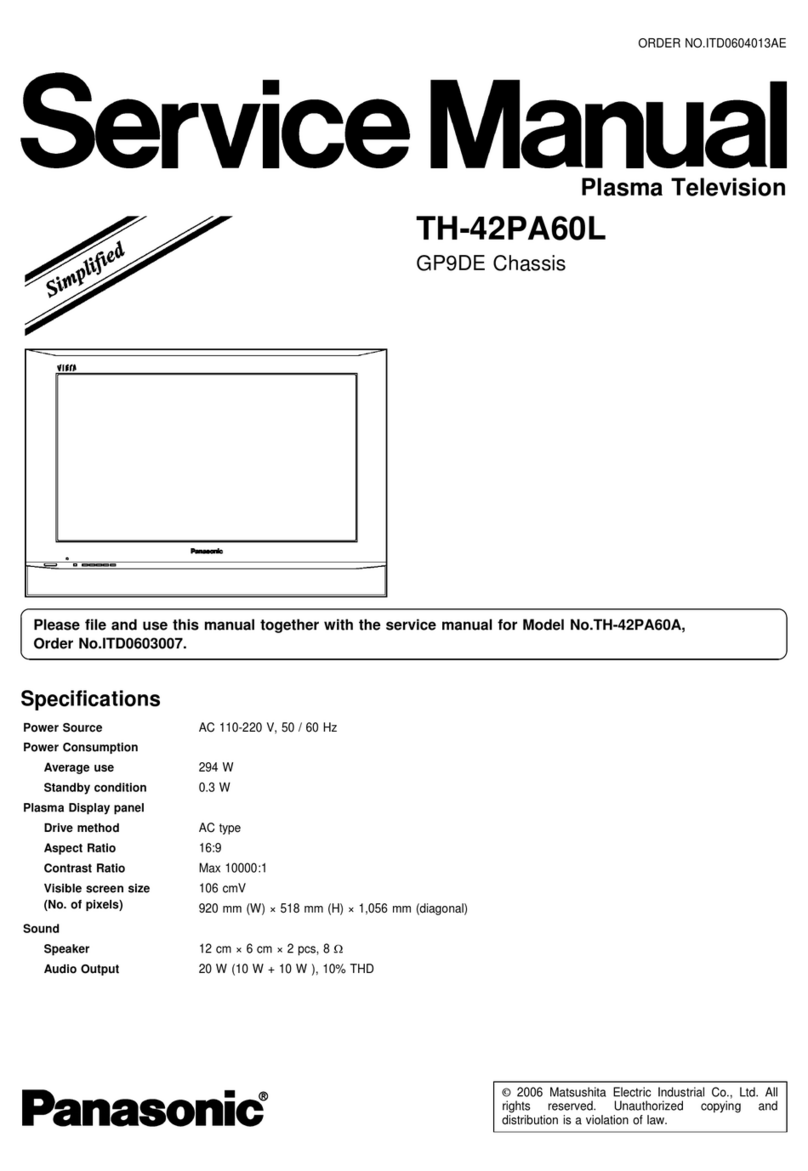
ORDER NO.PCZ1003015CE
Plasma Television
Model No. TX-P42S20E
TX-P42S20ES
TX-P42S20L
TX-PF42S20
TX-PR42S20
GPF13 E Chassis
A WARNING
This service information is esigne for experience repair technicians only an is not esigne for use by the general public.
It oes not contain warnings or cautions to a vise non-technical in ivi uals of potential angers in attempting to service a pro uct.
Pro ucts powere by electricity shoul be service or repaire only by experience professional technicians. Any attempt to service
or repair the pro uct or pro ucts ealt with in this service information by anyone else coul result in serious injury or eath.
IMPORTANT SAFETY NOTICE
There are special components use in this equipment which are important for safety. These parts are marke by A in the Schematic
Diagrams, Circuit Boar Diagrams, Explo e Views an Replacement Parts List. It is essential that these critical parts shoul be replace
with manufacturer's specifie parts to prevent shock, fire or other hazar s. Do not mo ify the original esign without permission of
manufacturer.
Panasonic © Panasonic Corporation 2010.
Unauthorize copying an istribution is a violation
of law.
TABLE OF CONTENTS
1 Safety Precautions
----------
1.1. General Gui elines —
1.2. Touch-Current Check-
2 Warning---------------------------
PAGE
------
3
------
3
------
3
------
4
2.1. Prevention of Electrostatic Discharge (ESD)
to Electrostatically Sensitive (ES) Devices
----------
4
2.2. About lea free sol er (PbF)-----------------------------5
3 Service Navigation
---------------------------------------------------6
3.1. PCB Layout-----------------------------------------------------6
3.2. Applicable signals---------------------------------------------7
4 Specifications--------------------------------------------------------- 8
105 Technical escriptions
-----------------------------------
5.1. Specification of KEY for CI Plus, DTCP-IP an
One-to-One
----------------------------------------------------10
6 Service Mode----------------------------------------------------------11
6.1. How to enter into Service Mo e-------------------------11
6.2. Option - Mirror-------------------------------------------------13
6.3. Service tool mo e--------------------------------------------13
6.4. Hotel mo e-----------------------------------------------------14
6.5. Data Copy by SD Car ------------------------------------15
7 Troubleshooting Guide
-------------------------------------------
18
7.1. Check of the IIC bus lines---------------------------------18
7.2. Power LED Blinking timing chart
-----------------------
19
7.3. No Power-------------------------------------------------------20
7.4. No Picture
------------------------------------------------------
21
7.5. Local screen failure
-----------------------------------------
22
8 Service Fixture & Tools
------------------------------------------
23
8.1. SC jig
------------------------------------------------------------ 23
9 isassembly and Assembly Instructions-----------------24
9.1. Remove the Rear cover----------------------------------24
9.2. Remove the AC inlet--------------------------------------24
9.3. Remove the P-Boar --------------------------------------24
9.4. Remove the Si e terminal cover an the Si e
shiel metal----------------------------------------------------24
9.5. Remove the Tuner unit-----------------------------------25
9.6. Remove the A-Boar --------------------------------------25
9.7. Remove the Speakers------------------------------------25
9.8. Remove the SM-Boar -----------------------------------25
9.9. Remove the SC-Boar ------------------------------------26
9.10. Remove the SS2-Boar ----------------------------------26
9.11. Remove the SS-Boar ------------------------------------26
9.12. Remove the Hanger metals an the Stan
brackets--------------------------------------------------------- 26
9.13. Remove the C1-Boar ------------------------------------27
9.14. Remove the C2-Boar ------------------------------------27
9.15. Remove the Plasma panel section from the
Cabinet assy (glass)----------------------------------------27
9.16. Remove the Glass hol ers
-----------------------------
28
9.17. Remove the K-Boar
--------------------------------------
28
9.18. Replace the plasma panel-------------------------------28
10 Measurements and Adjustments
----------------------------
29
10.1. A justment-----------------------------------------------------29
11 Block iagram
------------------------------------------------------
33
11.1. Main Block Diagram
---------------------------------------
33
11.2. Block (1/4) Diagram
---------------------------------------34
11.3. Block (2/4) Diagram---------------------------------------35
11.4. Block (3/4) Diagram---------------------------------------36
11.5. Block (4/4) Diagram---------------------------------------37
12 Wiring Connection iagram
12.1. Caution statement.
------
12.2. Wiring (1)
-------------------
12.3. Wiring (2) -------------------
13 Schematic iagram
------------
PAGE
----
39
----
39
----
39
----
40
----
41
----
41
----
42
----
43
----
44
----
45
----
46
----
47
----
48
----
49
----
50
----
51
----
52
----
53
----
54
----
55
----
56
----
57
----
58
----
59
----
60
----
61
13.1. Schematic Diagram Note
-------------------------
13.2. P-Boar (1/4) Schematic Diagram
------------
13.3. P-Boar (2/4) Schematic Diagram
------------
13.4. P-Boar (3/4) Schematic Diagram
------------
13.5. P-Boar (4/4) Schematic Diagram
------------
13.6. A-Boar (1/19) Schematic Diagram
-----------
13.7. A-Boar (2/19) Schematic Diagram
-----------
13.8. A-Boar (3/19) Schematic Diagram
-----------
13.9. A-Boar (4/19) Schematic Diagram
-----------
13.10. A-Boar (5/19) Schematic Diagram
-----------
13.11. A-Boar (6/19) Schematic Diagram
-----------
13.12. A-Boar (7/19) Schematic Diagram
-----------
13.13. A-Boar (8/19) Schematic Diagram
-----------
13.14. A-Boar (9/19) Schematic Diagram
-----------
13.15. A-Boar (10/19) Schematic Diagram
---------
13.16. A-Boar (11/19) Schematic Diagram
---------
13.17. A-Boar (12/19) Schematic Diagram
---------
13.18. A-Boar (13/19) Schematic Diagram
---------
13.19. A-Boar (14/19) Schematic Diagram
---------
13.20. A-Boar (15/19) Schematic Diagram
---------
13.21. A-Boar (16/19) Schematic Diagram
---------
13.22. A-Boar (17/19) an K-Boar Schematic
Diagram -------------------------------------------------------- 62
13.23. A-Boar (18/19) Schematic Diagram
-----------------
63
13.24. A-Boar (19/19) Schematic Diagram
-----------------
64
13.25. C1-Boar (1/2) Schematic Diagram
------------------
65
13.26. C1-Boar (2/2) Schematic Diagram
------------------
66
13.27. C2-Boar (1/2) Schematic Diagram
------------------
67
13.28. C2-Boar (2/2) Schematic Diagram
------------------
68
13.29. SC-Boar (1/4) Schematic Diagram
------------------
69
13.30. SC-Boar (2/4) Schematic Diagram
------------------
70
13.31. SC-Boar (3/4) Schematic Diagram
-------------------71
13.32. SC-Boar (4/4) Schematic Diagram
------------------
72
13.33. SS-Boar (1/2) Schematic Diagram
------------------
73
13.34. SS-Boar (2/2) an SS2-Boar Schematic
Diagram -------------------------------------------------------- 74
14 Printed Circuit Board--------------------------------------------- 75
14.1. P-Boar ---------------------------------------------------------75
14.2. K an SS2-Boar -------------------------------------------78
14.3. A-Boar ---------------------------------------------------------79
14.4. C1-Boar
--------------------------------------------------------81
14.5. C2-Boar ------------------------------------------------------- 82
14.6. SC-Boar -------------------------------------------------------83
14.7. SS-Boar ------------------------------------------------------ 85
15 Exploded View and Replacement Parts List
-------------
87
15.1. Explo e View an Mechanical Replacement
Parts List------------------------------------------------------- 87
15.2. Electrical Replacement Parts List
---------------------
95
2
1 Safety Precautions
1.1. General Guidelines
1. When servicing, observe the original lea ress. If a short circuit is foun , replace all parts which have been overheate or
amage by the short circuit.
2. After servicing, see to it that all the protective evices such as insulation barriers, insulation papers shiel s are properly
installe .
3. After servicing, make the following leakage current checks to prevent the customer from being expose to shock hazar s.
4. When servicing, observe the original lea ress. If a short circuit is foun , replace all parts which have been overheate or
amage by the short circuit.
5. After servicing, see to it that all the protective evices such as insulation barriers, insulation papers shiel s are properly
installe .
6. After servicing, make the following leakage current checks to prevent the customer from being expose to shock hazar s.
1.2. Touch-Current Check
1. Plug the AC cor irectly into the AC outlet. Do not use an isolation transformer for this check.
2. Connect a measuring network for touch currents between each expose metallic part on the set an a goo earth groun
such as a water pipe, as shown in Figure 1.
3. Use Leakage Current Tester (Simpson 228 or equivalent) to measure the potential across the measuring network.
4. Check each expose metallic part, an measure the voltage at each point.
5. Reserve the AC plug in the AC outlet an repeat each of the above measure.
6. The potential at any point (TOUGH CURRENT) expresse as voltage U1 an U2, oes not excee the following values:
For a. c.: U1 = 35 V (peak) an U2 = 0.35 V (peak);
For . c.: U1 = 1.0 V,
Note:
The limit value of U2 = 0.35 V (peak) for a. c. an U1 = 1.0 V for . c. correspon to the values 0.7 mA (peak) a. c. an 2.0
mA . c.
The limit value U1 = 35 V (peak) for a. c. correspon to the value 70 mA (peak) a. c. for frequencies greater than 100 kHz.
7. In case a measurement is out of the limits specifie , there is a possibility of a shock hazar , an the equipment shoul be
repaire an rechecke before it is returne to the customer.
Measuring network for TOUCH CURRENTS
COLD
WATER PIPE
(EARTH GROUND)
Rs=
1500Q_L Cs=
0.22|jF
10kQ
-1 k 1
-------
1
Ro=
----------------
J
500Q
'U1 =
r
= 0.022|jF (V)
J Q L jJ J U U i i U 1 —|— и . и ^ г ф Г ^ V J | U2 (V)
APPLIANCES
EXPOSED
METAL PARTS
Resistance values in ohms (Q)
V: Voltmeter or oscilloscope
(r.m.s. or peak rea ing)
Input resistance: > 1 MQ
Input capacitance: < 200 pF
Frequency range: 15 Hz to 1 MHz an .c. respectively
NOTE - Appropriate measures shoul be taken to obtain the correct value in case of non-sinusoi al waveforms.
Figure 1
3
2 Warning
2.1. Prevention of Electrostatic ischarge (ES ) to Electrostatically
Sensitive (ES) evices
Some semicon uctor (soli state) evices can be amage easily by static electricity. Such components commonly are calle Elec
trostatically Sensitive (ES) Devices. Examples of typical ES evices are integrate circuits an some fiel -effect transistors an
semicon uctor [chip] components. The following techniques shoul be use to help re uce the inci ence of component amage
cause by electrostatic ischarge (ESD).
1. Imme iately before han ling any semicon uctor component or semicon uctor-equippe assembly, rain off any ESD on your
bo y by touching a known earth groun . Alternatively, obtain an wear a commercially available ischarging ESD wrist strap,
which shoul be remove for potential shock reasons prior to applying power to the unit un er test.
2. After removing an electrical assembly equippe with ES evices, place the assembly on a con uctive surface such as alumi
num foil, to prevent electrostatic charge buil up or exposure of the assembly.
3. Use only a groun e -tip sol ering iron to sol er or unsol er ES evices.
4. Use only an anti-static sol er removal evice. Some sol er removal evices not classifie as [anti-static (ESD protecte )] can
generate electrical charge sufficient to amage ES evices.
5. Do not use freon-propelle chemicals. These can generate electrical charges sufficient to amage ES evices.
6. Do not remove a replacement ES evice from its protective package until imme iately before you are rea y to install it. (Most
replacement ES evices are package with lea s electrically shorte together by con uctive foam, aluminum foil or compara
ble con uctive material).
7. Imme iately before removing the protective material from the lea s of a replacement ES evice, touch the protective material
to the chassis or circuit assembly into which the evice will be installe .
Caution
Be sure no power is applie to the chassis or circuit, an observe all other safety precautions.
8. Minimize bo ily motions when han ling unpackage replacement ES evices. (Otherwise ham less motion such as the brush
ing together of your clothes fabric or the lifting of your foot from a carpete floor can generate static electricity (ESD) sufficient
to amage an ES evice).
4
Note: Lead is listed as (Pb) in the periodic table of elements.
In the information below, Pb will refer to Lead solder, and PbF will refer to Lead Free Solder.
The Lead Free Solder used in our manufacturing process and discussed below is (Sn+Ag+Cu).
That is Tin (Sn), Silver (Ag) and Copper (Cu) although other types are available.
This mo el uses Pb Free sol er in it's manufacture ue to environmental conservation issues. For service an repair work, we'
suggest the use of Pb free sol er as well, although Pb sol er may be use .
PCBs manufacture using lea free sol er will have the PbF within a leaf Symbol PbF stampe on the back of PCB.
Caution
• Pb free sol er has a higher melting point than stan ar sol er. Typically the melting point is 50 ~ 70 °F (30~40 °C) higher. Please
use a high temperature sol ering iron an set it to 700 ± 20 °F (370 ± 10 °C).
• Pb free sol er will ten to splash when heate too high (about 1100 °F or 600 °C).
If you must use Pb sol er, please completely remove all of the Pb free sol er on the pins or sol er area before applying Pb sol
er. If this is not practical, be sure to heat the Pb free sol er until it melts, before applying Pb sol er.
• After applying PbF sol er to ouble layere boar s, please check the component si e for excess sol er which may flow onto the
opposite si e. (see figure below)
component component
remove all of the ^1П\
excess sol er
2.2. About lead free solder (PbF)
slice
\
sol er
Suggested Pb free solder
There are several kin s of Pb free sol er available for purchase. This pro uct uses Sn+Ag+Cu (tin, silver, copper) sol er. How
ever, Sn+Cu (tin, copper), Sn+Zn+Bi (tin, zinc, bismuth) sol er can also be use .
5
3 Service Navigation
3.1. PCB Layout
Remove the Rear cover
(1) (1)
(2) (2) (2) (2) (2)
Remove:
2screws (1) THEL052Z
11screws (2) XTB4+12GFJK
5screws (3) THEJ0339
2screws (4) XSB3+6FJ
2screws (5) XTV3+10JFJK
2screws (6) XYN3+F10FJK
4screws (7) TKKL5493
Boar Name Function
P Power Supply
A DC-DC Converter, Tuner
Speaker out, AV Terminal, HDMI in, SD Car
Digital Signal Processor, PEAKS-sLD
Format Converter, Plasma AI, Sub-Fiel Processor
Power Switch, Key Switch
K Remote receiver, Power LED, C.A.T.S. sensor
Boar Name Function
C1 Data Driver (Lower Right)
C2 Data Driver (Lower Left)
SC Scan Drive
SS Sustain Drive
SS2 Sustain out (Lower)
SM Scan out
Non serviceable.
SM-Boar shoul be exchange for service.
6
3.2. Applicable signals
COMPONENT (Y, PB, PR), H MI
* Mark: Applicable input signal for Component (Y, PB, PR) an HDMI
Signal name COMPONENT HDMI
525 (480) / 60i * *
525 (480) / 60p * *
625 (576) / 50i * *
625 (576) / 50p * *
750 (720) / 60p * *
750 (720) / 50p * *
1,125 (1,080) / 60i * *
1,125 (1,080) / 50i * *
1,125 (1,080) / 60p *
1,125 (1,080) / 50p *
1,125 (1,080) / 24p *
PC (from H MI terminal)
Applicable input signal for PC is basically compatible to HDMI stan ar timing.
Signal name Horizontal frequency (kHz) Vertical frequency (Hz)
640 x 480 @60 Hz 31.47 60.00
750 (720) / 60p 45.00 60.00
1,125 (1,080) / 60p 67.50 60.00
Note
• Signals other than above may not be isplaye properly.
• The above signals are reformatte for optimal viewing on your isplay.
• PC signal is magnifie or compresse for isplay, so that it may not be possible to show fine etail with sufficient clarity.
7
4 Specifications
Power Source
Power Consumption
On mode Average Power Consumption
Power Consumption in Standby mode
isplay panel
Aspect Ratio
Visible screen size
Number of pixels
Sound Speaker
Audio Output
Headphones
Receiving Systems / Band name
Aerial - input
Operating Conditions
Connection Terminals
AV1 (Scart terminal)
AV2 (Scart terminal)
AV3 VI EO
AU IO L - R
COMPONENT
VI EO
AU IO L - R
Others
H MI1 / 2 / 3
Card slot
Output
AU IO L - R
IGITAL AU IO OUT
imensions (W x H x )
Mass
AC 220-240 V, 50 / 60 Hz
275 W
117 W
0.4 W (Without monitor out recor ing)
15 W (With monitor out recor ing)
16:9
106 cm ( iagonal)
921 mm (W) x 518 mm (H)
2,073,600 (1,920 (W) x 1,080 (H)) [5,760 x 1,080 ots]
160 mm x 40 mm x 2 pcs, 6 Q
20 W ( 10 W + 10 W )
M3 (3.5 mm) stereo mini Jack x 1
PAL B, G, H, I, SECAM B, G, SECAM L, L’
VHF E2 - E12
VHF A - H (ITALY)
CATV (S01 - S05)
CATV S11 - S20 (U1 - U10)
PAL , K, SECAM , K
VHF R1 - R2
VHF R6 - R12
PAL 525/60
M.NTSC
NTSC (AV input only)
VB-T
VB-C
VHF H1 - H2 (ITALY)
UHF E21 - E69
CATV S1 - S10 (M1 - M10)
CATV S21 - S41 (Hyperban )
VHF R3 - R5
UHF E21 - E69
Playback of NTSC tape from some PAL Vi eo recor ers (VCR)
Playback from M. NTSC Vi eo recor ers (VCR)
Playback from NTSC Vi eo recor ers (VCR)
Digital terrestrial services (MPEG2 an MPEG4-AVC(H.264))
Digital cable services (MPEG2 an MPEG4-AVC(H.264))
Countries that DVB-C is available: Germany, Switzerlan ,
Denmark, Swe en, Norway, Finlan , Netherlan s
• Check the latest information on the available services at the following website. (English only)
http://panasonic.jp/support/global/cs/
VH F/ UHF
Temperature:
Humi ity: 0 °C - 35 °C
20 % - 80 % RH (non-con ensing)
21 Pin terminal (Au io/Vi eo in, Au io/Vi eo out, RGB in, Q-Link)
21 Pin terminal (Au io/Vi eo in, Au io/Vi eo out, RGB in, S-Vi eo in, Q-Link)
RCA PIN Type x 1
RCA PIN Type x 21.0 V [p-p] (75 Q)
0.5 V [rms]
Y
Pb, Pr
RCA PIN Type x 2
1.0 V [p-p] (inclu ing synchronization)
± 0.35 V [p-p]
0.5 V [rms]
TYPE A Connectors
HDMI1 / 3 : HDMI (Version 1.3a with x.v. Colour.)
HDMI2 : HDMI (Version 1.4 with Au io Return Channel) an
HDMI (Version 1.3a with x.v. Colour.)
• This TV supports [ HDAVI Control 5 ] function.
SD Car slot x 1
Common Interface slot x 1
RCA PIN Type x 2 0.5 V [rms] (high impe ance)
PCM / Dolby Digital / DTS, Fiber optic
1.029 mm x 704 mm x 334 mm (With Pe estal)
1.029 mm x 661 mm x 93 mm (TV only)
24.5 kg Net (With Pe estal)
23.0 kg Net (TV only)
8
Note
• Design an Specifications are subject to change without notice. Mass an Dimensions shown are approximate.
• This equipment complies with the EMC stan ar s liste below.
EN55013, EN61000-3-2, EN61000-3-3, EN55020.
9
5 Technical escriptions
5.1. Specification of KEY for CI Plus, TCP-IP and One-to-One
5.1.1. General information:
1. EEPROM (IC8950) for spare parts has the see of KEY for each.
2. The final KEY ata will be generate by Peaks IC (IC8001) when SELF CHECK was one an are store in both Peaks IC
(IC8001) an EEPROM (IC8950).
Three KEY are not generate for all mo els.
The necessary KEY are only generate an store epen on the feature of mo els.
5.1.2. Replacement of ICs:
When Peaks IC (IC8001) is replace , EEPROM (IC8950) shoul be also replace with new one the same time.
When EEPROM (IC8950) is replace , Peaks IC (IC8001) is not necessary to be replace the same time.
After the replacement of IC, SELF CHECK shoul be one to generate the final KEY ata.
How to SELF CHECK: While pressing [VOLUME ( - )] button on the main unit, press [MENU] button on the remote control for more
than 3 secon s.
TV will be force to the factory shipment setting after this SELF CHECK.
5.1.3. Model and Keys:
Mo el No. Keys
CI Plus DTCP-IP One-to-One
(For USB Rec.)
TX-P42S20E Yes None None
TX-P42S20ES Yes None None
TX-P42S20L Yes None None
TX-PF42S20 None None None
TX-PR42S20 None None None
10
6 Service Mode
6.1. How to enter into Service Mode
While pressing [VOLUME ( - )] button of the main unit, press [0] button of the remote control three times within 2 secon s.
Software version ■
Picture a justment
----------
White balance a justment
Option setting
-----------------
Vsus a justment
-------------
Aging
------------------------------
SERVICE
ADJUST
WB-ADJ
OPTION
VSUS
AGING
SRV-TOOL
1
PEAKS SOFT *.*** OPTION 1 **
PEAKS EEP * * * * * * * * OPTION 2 **
LSI PACKAGE *.*** OPTION 3 **
LSI RELEASE ***** Mo el ID **
STBY SOFT ***** ********
STBYEEP * ** **** ********
STBY ROMCOR *.**** R/E Cnt ***/***
PDPSOFT * * * * * *
PDPEEP * ***
PDP DCC ** **
PDP PDPOM
I Sub Item
+ I
Ia d ju s t " i ’
'CONTRAST ' 'OOOOi
YMAX
6.1.1. Key command
[1] button...Main items Selection in forwar irection
[2] button...Main items Selection in reverse irection
[3] button...Sub items Selection in forwar irection
[4] button...Sub items Selection in reverse irection
[RED] button...All Sub items Selection in forwar irection
[GREEN] button...All Sub items Selection in reverse irection
[VOL] button...Value of sub items change in forwar irection ( + ), in reverse irection ( - )
11
6.1.2. Contents of adjustment mode
• Value is shown as a hexa ecimal number.
• Preset value iffers epen ing on mo els.
• After entering the a justment mo e, take note of the value in each item before starting a justment.
Main item Sub item Sample ata Remark
ADJUST CONTRAST 23A
COLOR 2B
TINT 00
SUB-BRT 80C
H-POS 0
H-AMP 0
V-POS 0
V-AMP 0
WB-ADJ R-CUT 80
G-CUT 80
B-CUT 80
R-DRV F1
G-DRV FC
B-DRV DO
ALL-CUT 80
ALL-DRV FC
OPTION Panel-Type 42FHD Factory
Boot ROM Preset
STBY-SET 00
EMERGENCY ON
Y/C Delay 0
OPT 1 00011100
OPT 2 11101111
OPT 3 00000001
EDID-CLK HIGH
MIRROR 00 (See next)
VSUS
AGING ALL WHITE Built-in test
Al ALL BLUE + WHITE FLAME patterns can be
isplaye .
Al ALL GREEN
Al ALL RED
LOW STEP WHITE
LOW STEP BLUE
LOW STEP GREEN
LOW STEP RED
RAMP WHITE
RAMP RED
RAMP GREEN
RAMP BLUE
A-ZONE B-ZONE
1% WINDOW
COLOR BAR
9 POINT BRIGHTNESS
WHITE FLAME
Al ALL BLUE
TWICE FIXATION 1% WINDOW
SCROLL
ON/OFF OR RGBW
R/G/B/W AGING MODE
0.5 TIME FIXATION ALL WHITE
ALL WHITE WITH COUNT
SRV-TOOL see next
Destination Conti. EU Irelan France Russia
Check sum 0xa6 a Охабсс 0xa775 0xa68c
EDID O ec ccc-
6.1.3. How to exit
Switch off the power with the [POWER] button on the main unit or the [POWER] button on the remote control.
12
6.2. Option - Mirror
Picture can be reverse left an right or up an own.
00
01
02
Default (Normal picture is isplaye )
Picture is reverse left an right.
Picture is reverse up an own.
Hint : If the efective symptom (e.g. Vertical bar or Horizontal bar) is move by selection of this mirror, the possible cause is in
A-boar .
6.3. Service tool mode
6.3.1. How to access
1. Select [SRV-TOOL] in Service Mo e.
2. Press [OK] button on the remote control.
Display of TD2Microco e version —
Display of Flash ROM maker co e -
Display of SOS History ----------------
SRV-TOOL
TD2Microco e:00500910
Flash ROM : 1 - 227E
PTCT : 00 . 00 . 00 . 00 . 00 Time 00000:40 On/Off 0000022 . POWER ON TIME/COUNT
Press [MUTE] button (3sec)
6.3.2. isplay of SOS History
SOS History (Number of LED blinking) in ication.
From left si e; Last SOS, before Last, three occurrence before, 2n occurrence after shipment, 1 st occurrence after shipment.
This in ication will be cleare by [Self-check in ication an force to factory shipment setting].
6.3.3. POWER ON Time, On/Off
Note : To isplay TIME/COUNT menu, highlight position, then press MUTE for 3sec.
Time : Cumulative power on time, in icate hour : minute by ecimal
On/Off : Number of On/Off switching by ecimal
Note : This in ication will not be cleare by either of the self-checks or any other comman .
6.3.4. Exit
1. Disconnect the AC cor from wall outlet or switch off the power with [ Power ] button on the main unit.
13
6.4. Hotel mode
1. Purpose
Restrict a function for hotels.
2. Access comman to the Hotel mo e setup menu
In or er to isplay the Hotel mo e setup menu, please
enter the following comman (within 2 second).
[TV] : Vol. [Down] + [REMOTE] : AV (3 times)
Then, the Hotel mo e setup menu is isplaye .
Hotel Mo e
Hotel Mo e 1 Off
_______________________
|
Initial INPUT 1 Off 1
Intial POS 1 Off 1
Intial VOL Level Го т |
Maximum Vol Level 1 100 I
Button Lock Го т |
Remote Lock Г Ш |
Select
^o E X IT
(< ой- Change
~ °RETURN
3. To exit the Hotel mo e setup menu
Disconnect AC power cor from wall outlet.
4. Explain the Hotel mo e setup menu
item Function
Hotel Mo e Select hotel mo e ON/OFF
Initial INPUT Select input signal mo es.
Set the input, when each time power is switche
on.
Selection :
Off/DVB-C/DVB-T/Analog/AV1/AV2/AV2S/AV3/
COMPONENT/HDMI1/HDMI2/HDMI3
• Off: give priority to a last memory. However,
Euro mo el is compulsorily set to TV.
• AVnS/AVnC: only Euro mo el selectable
• PC: selectable with VGA option
Initial POS Select programme number.
Selection :
Off/0 to 99
• Off: give priority to a last memory
Initial VOL level A just the volume when each time power is
switche on.
Selection/Range :
Off/0 to 100
• Off: give priority to a last memory
Maximum VOL
level A just maximum volume.
Range :
0 to 100
Button lock Select local key con itions.
Selection :
Off/SETUP/MENU/ALL
• Off: altogether vali
• SETUP: only F-key is invali
(Tuning gui e(menu) can not be selecte .)
• MENU: only F-key is invali
(only Volume/Mute can be selecte .)
• ALL: altogether invali .
Remote lock Select remote control key con itions.
Selection :
Off/SETUP/MENU
• Off: altogether vali
• SETUP: only Setup menu is invali
• MENU: Picture/Soun /Setup menu are invali
14
6.5. ata Copy by S Card
6.5.1. Purpose
(a) Board replacement (Copy the data when exchanging A-board):
When exchanging A-boar , the ata in original A-boar can be copie to SD car an then copy to new A-boar .
TV (Before exchanging)
Copy to SD car
Ap. SD
'Ч (After exchanging)
Following ata can be copie .
User setting ata
(incl. Hotel mo e setting ata)
Channel scan ata
A justment an factory preset ata
Copy back from SD car
(b) Hotel (Copy the data when installing a number of units in hotel or any facility):
When installing a number of units in hotel or any facility, the ata in master TV can be copie to SD car an then copy to other
TVs.
6.5.2. Preparation
Make pw file as startup file for (a) or (b) in a empty SD car .
1. Insert a empty SD car to your PC.
2. Right-click a blank area in a SD car win ow, point to New, an then click text ocument. A new file is create by efault
(New Text Document.txt).
3. Right-click the new text ocument that you just create an select rename, an then change the name an extension of the
file to the following file name for (a) or (b) an press ENTER.
File name:
(a) For Boar replacement : boar replace.pw
(b) For Hotel : hotel.pw
Note:
Please make only one file to prevent the operation error.
No any other file shoul not be in SD car .
15
6.5.3. ata copy from TV set to S Card
1. Turn on the TV set.
2. Insert SD car with a startup file (pw file) to SD slot.
On-screen Display will be appeare accor ing to the startup file automatically.
3. Input a following passwor for (a) or (b) by using remote control.
(a) For Boar replacement : 2770
(b) For Hotel : 4850
Data will be copie from TV set to SD car .
It takes aroun 2 to 6 minutes maximum for copying.
4. After the completion of copying to SD car , remove SD car from TV set.
5. Turn off the TV set.
Note:
Following new fol er will be create in SD car for ata from TV set.
(a) For Boar replacement : user_setup
(b) For Hotel : hotel
16
6.5.4. ata copy from to S Card to TV set
1. Turn on the TV set.
2. Insert SD car with Data to SD slot.
On-screen Display will be appeare accor ing to the Data fol er automatically.
3. Input a following passwor for (a) or (b) by using remote control.
(a) For Boar replacement : 2771
(b) For Hotel : 4851
Data will be copie from SD car to TV set.
4. After the completion of copying to SD car , remove SD car from TV set.
(a) For Boar replacement : Data will be elete after copying (Limite one copy).
(b) For Hotel : Data will not be elete an can be use for other TVs.
5. Turn off the TV set.
1. Depen ing on the failure of boar s, function of Data copy for boar replacement oes not work.
2. This function can be effective among the same mo el numbers.
Note:
(e.g. For exchanging
repair boar )
Performing
Completion
17
7 Troubleshooting Guide
Use the self-check function to test the unit.
1. Checking the IIC bus lines
2. Power LED Blinking timing
7.1. Check of the IIC bus lines
7.1.1. How to access
7.1.1.1. Self-check indication only:
Pro uce TV reception screen, an while pressing [VOLUME ( - )] button on the main unit, press [OK] button on the remote control
for more than 3 secon s.
7.1.1.2. Self-check indication and forced to factory shipment setting:
Caution:
New key will be generated and previous TV programmes recorded in USB H will not be viewed. (See Chap.5)
Pro uce TV reception screen, an while pressing [VOLUME ( - )] button on the main unit, press [MENU] button on the remote con
trol for more than 3 secon s.
7.1.2. Screen display
42FHD Panasonic 2010PDP
SET SELF CHECK COMPLETE
PEAKS-SOFT * _***
PEAKS-EEP ** ** ** **
LSI-PACKAGE *_***
LSI-RELEASE * **
STBY-SOFT *****
STBY-EEP *******
STBY-ROMCORR *****
PDP-MCU ******
PDP-EEP **_ **
PDP-DCC **_ **
PDP-PDPOM **_ **
SUM ****
Mo el ID **
********
********
EDID
TUN OK
STBY OK
MEM1 OK
MEM2 OK
ADAM OK
AVSW OK
PDROM OK
OFDM OK
TEMP OK
VIF OK
ID OK
* : Displaye for E mo el only.
7.1.3. Check Point
Confirm the following parts if NG was isplaye .
Display Ref. No. Description P.C.B.
TUN TU2901A TUNER A-Boar
STBY IC8001 MPU (PEAKS-sLD) A-Boar
MEM1 IC1101 EEPROM (MPU) A-Boar
MEM2 IC8950 EEPROM (PEAKS-sLD) A-Boar
ADAM IC8001 А-chip (PEAKS-sLD) A-Boar
AVSW IC3000 Au io/Vi eo SW A-Boar
PDROM IC9300 PD4 A-Boar
OFDM IC8300 Digital emo ulator A-Boar
TEMP IC1000 Temp Sensor A-Boar
VIF TU2901A TUNER A-Boar
7.1.4. Exit
Disconnect the AC cor from wall outlet or switch off the power with [ Power ] button on the main unit.
18
7.2. Power LE Blinking timing chart
1. Subject
Information of LED Flashing timing chart.
2. Contents
When an abnormality has occurre the unit, the protection circuit operates an reset to the stan by mo e. At this time, the
efective block can be i entifie by the number of blinks of the Power LED on the front panel of the unit.
19
7.3. No Power
First check point
There are following 2 states of No Power in ication by power LED.
1. No lit
2. Re is lit then turns re blinking a few secon s later. (See 6.2.)
20

Other manuals for Viera TX-P42S20L

1

This manual suits for next models

4

Other Panasonic Plasma TV manuals

Panasonic Viera TH-42PX8A User manual

Panasonic

Panasonic Viera TH-42PX8A User manual

Panasonic Viera TX-P42U30B User manual

Panasonic

Panasonic Viera TX-P42U30B User manual

Panasonic TH-P42X30A User manual

Panasonic

Panasonic TH-P42X30A User manual

Panasonic TCP60ZT60 User manual

Panasonic

Panasonic TCP60ZT60 User manual

Panasonic Viera TH-37PX7E User manual

Panasonic

Panasonic Viera TH-37PX7E User manual

Panasonic TX-PR42G10 User manual

Panasonic

Panasonic TX-PR42G10 User manual

Panasonic TH50PZ750U - 50" Plasma TV User manual

Panasonic

Panasonic TH50PZ750U - 50" Plasma TV User manual

Panasonic Viera TX-P42GT50Y User manual

Panasonic

Panasonic Viera TX-P42GT50Y User manual

Panasonic Viera TC-P50UT50 User manual

Panasonic

Panasonic Viera TC-P50UT50 User manual

Panasonic TC-P55VT60 User manual

Panasonic

Panasonic TC-P55VT60 User manual

Panasonic Viera VT60P Series User manual

Panasonic

Panasonic Viera VT60P Series User manual

Panasonic Viera TH-P46U20K User manual

Panasonic

Panasonic Viera TH-P46U20K User manual

Panasonic TH-42PV80D User manual

Panasonic

Panasonic TH-42PV80D User manual

Panasonic Viera TH-42PV80AZ User manual

Panasonic

Panasonic Viera TH-42PV80AZ User manual

Panasonic TH50PZ750U - 50" Plasma TV User manual

Panasonic

Panasonic TH50PZ750U - 50" Plasma TV User manual

Panasonic TH-P58S20M User manual

Panasonic

Panasonic TH-P58S20M User manual

Panasonic Viera TH-58PE75U User manual

Panasonic

Panasonic Viera TH-58PE75U User manual

Panasonic Viera TH-42PY85P User manual

Panasonic

Panasonic Viera TH-42PY85P User manual

Panasonic TH-58PY700M User manual

Panasonic

Panasonic TH-58PY700M User manual

Panasonic TCL37D2 - 37" LCD TV User manual

Panasonic

Panasonic TCL37D2 - 37" LCD TV User manual

Panasonic Viera TC-P42G25 User manual

Panasonic

Panasonic Viera TC-P42G25 User manual

Panasonic TC-42PX14 - 42" Plasma Panel User manual

Panasonic

Panasonic TC-42PX14 - 42" Plasma Panel User manual

Panasonic TC-P42U1 - 42" Plasma TV User manual

Panasonic

Panasonic TC-P42U1 - 42" Plasma TV User manual

Panasonic WT60 Series Assembly instructions

Panasonic

Panasonic WT60 Series Assembly instructions

Popular Plasma TV manuals by other brands

Samsung HP-P5071 manual

Samsung

Samsung HP-P5071 manual

Samsung PN51F8500AF E-manual

Samsung

Samsung PN51F8500AF E-manual

Samsung PN42C430A1DXZA brochure

Samsung

Samsung PN42C430A1DXZA brochure

Hitachi P50S601 - 50" Plasma TV operating guide

Hitachi

Hitachi P50S601 - 50" Plasma TV operating guide

LG 50PC1RR Series Service manual

LG

LG 50PC1RR Series Service manual

Microtek MHP1-HD user manual

Microtek

Microtek MHP1-HD user manual

ViewSonic NextVision VPW505 Specifications

ViewSonic

ViewSonic NextVision VPW505 Specifications

LG 42PW340 Service manual

LG

LG 42PW340 Service manual

LG 60PZ750 Specifications

LG

LG 60PZ750 Specifications

Zenith Z60PV220 Product description

Zenith

Zenith Z60PV220 Product description

LG 42PQ100R Service manual

LG

LG 42PQ100R Service manual

LG 60PZ550 Specifications

LG

LG 60PZ550 Specifications

Toshiba 42HP84 - 42" Plasma TV Specifications

Toshiba

Toshiba 42HP84 - 42" Plasma TV Specifications

Philips 42PF9936/37 Technical specifications

Philips

Philips 42PF9936/37 Technical specifications

Samsung PS42B450 user manual

Samsung

Samsung PS42B450 user manual

Magnavox Plasma Television user guide

Magnavox

Magnavox Plasma Television user guide

Samsung PS-42D4S Connecting guide

Samsung

Samsung PS-42D4S Connecting guide

Philips 42PF9956/37 Specifications

Philips

Philips 42PF9956/37 Specifications

manuals.online logo
manuals.online logoBrands
  • About & Mission
  • Contact us
  • Privacy Policy
  • Terms and Conditions

Copyright 2025 Manuals.Online. All Rights Reserved.