manuals.online logo
Brands
  1. Home
  2. •
  3. Brands
  4. •
  5. Panasonic
  6. •
  7. Stereo System
  8. •
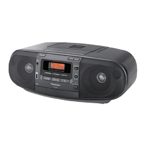
  9. Panasonic RX-ES22E User manual

Panasonic RX-ES22E User manual

Order No: MD0201021C2
PortableStereo CD System
RX-ES22E / RX-ES22EB / RX-ES22EG
Colour
(S)..........Silver Type
Tape Deck: SG2Mechanism Series
Traverse deck: RAE0155Z-1V Mechanism Series
SPECIFICATIONS
1
RADIO
Frequencyrange
AM 522-1629 kHz (9kHz steps)
FM 87.5-108 MHz (50 kHz steps)
TAPE RECORDER
Track System 4 track, 2channel, stereo
Recording system AC bias
Erasing system Multi Polemagnet
Monitorsystem Variablesound monitor
Frequencyrange
Normal position 50-14000 Hz
CD PLAYER
Sampling frequency 44.1kHz
Decoding 16 bit linear
Beam source Semiconductorlaser
(wavelength780 nm)
No. of channels 2channel, stereo
Wowand flutter Belowmeasurablelimit
D/Aconverter MASH (1bit DAC)
GENERAL
Power requirement
AC 230-240 V, 50 Hz
Power consumption 23 W
Battery 12 V [Eight R20/LR20 (D, UM-1)
batteries]
Donot use rechargeabletypebatteries
Memorybackup forcomputer/
clock 6V [FourR6/LR6(AA, UM-3)
batteries]
Donot use rechargeabletypebatteries
Speakers 8 cm 2.7 x2
Jacks
Output Phones: 3.5mm stereo(16-32 )
Dimensions(WxH xD) 529 x144 x276 mm
Mass 4.0kgwithout batteries
Notes:
1. Mass and dimensionsshown areapproximate.
2. Specificationsaresubject to changewithoutnotice.
2002 Matsushita Electronics (S) Pte. Ltd. All rights reserved.
Unauthorized copying and distribution isaviolation of law.
2
1. Before Repair and Adjustment
Disconnect AC power, discharge PowerSupplyCapacitors C301 through a 10 , 5 W resistor
toground. DO NOTSHORT-CIRCUITDIRECTLY (witha screwdriverblade, forinstance), as this
maydestroysolidstate devices.
Afterrepairs are completed, restore powergraduallyusing a variac, toavoidovercurrent.
Current consumption at AC 220 V, 240 V, 60 Hz inNO SIGNALmode shouldbe ~100 mA
respectively.
2. Protection Circuitry
The protection circuitrymayhave operatedif eitherof the following conditions are noticed:
-Nosound isheard when the power isturned on.
-Stops during aperformance.
The function of this circuitryis toprevent circuitrydamage if, forexample, the positive and
negative speakerconnection wires are “shorted”, orif speakersystems withanimpedance less
thanthe indicatedratedimpedance of the amplifierare used.
If this occurs, followthe procedure outlines below:
1. Turn off the power.
2. Determine the cause of the problem and correct it.
3. Turn on the power once againafter one minute.
Note:
Whenthe protection circuitryfunctions, the unit will not operate unless the poweris first turned
off and thenon again.
3. Accessories Remote Control Transmitter.....1 pc
AC Mains Lead(E/EG).....1 pc
3
AC Mains Lead(EB).....1 pc
4. Handling Precautions For Traverse Deck
The laserdiode inthe traverse deck (optical pickup) maybreak downdue topotential difference
causedbystatic electricityof clothes orhumanbody. So, be careful of electrostatic breakdown
during repairof the traverse deck (optical pickup).
-Handling of traverse deck (optical pickup)
1. Donot subject the traverse deck (optical pickup) to static
electricityas itisextremelysensitive to electrical shock.
2. To prevent the breakdownof the laser diode, an antistatic
shorting pinisinserted into the flexibleboard (FFCboard).
3. Take care not to applyexcessive stress to the flexibleboard (FFC
board). When removing or connecting the short pin, finish the job
4
inas short time as possible.
4. Donot turn the variableresistor (laser power adjustment). Ithas
alreadybeen adjusted.
-Grounding for electrostaticbreakdownprevention
1. Human bodygrounding
Use the anti-staticwrist strap to discharge the staticelectricity
from your body.
2. Work tablegrounding.
Put aconductive material (sheet) or steel sheet on the area where
the traverse deck (optical pickup) isplace, and ground the sheet.
Caution:
The staticelectricityof your clothes will not be grounded through
the wrist strap. So, take care not to let your clothes touch the
traverse deck (optical pickup). /
Caution whenreplacing the Traverse Deck
The traverse deck has ashort point shorted with solder to protect
the laser diode against electrostatics breakdown. Besure to
remove the solder from the short point before making connections.
5
5. Precaution of Laser Diode
Caution:
Thisproduct utilizers aclass 1laser. Invisiblelaser radiation is
emitted from the optical pick up lens.
When the unitisturned on:
1. Donot disassemblethe optical pick up unit, since radiation from
exposed laser diode isdangerous.
2. Donot adjust the variableresistor on the pick up unit. Itwas
alreadyadjusted.
3. Donot look at the focus lens using optical instruments.
4. Recommend not to look at pick up lens for along time.
ACHTUNG:
Dieses Produkt enthälteine Laserdiode. Imenigeschalteten
Zustand wird unsichtbare Laserstrahlung von der Lasereinheit
abgestrahlt. / Wellenlänge :780nm / MaximaleStrahlungsleistung
der Lasereinheit:100 W/VDE/ DieStrahlung an der Lasereinheit
ist ungefährlich, wenn folgende Punkte beachtet werden:
1. DieLasereinheitnicht zerlegen, da dieStrahlung an der
freigelegten Laserdiode gefährlich ist.
2. Den werkseitigjustierten Einstellregler der Lasereinhitnicht
verstellen.
3. Nicht mitoptischen Instrumenten indieFokussierlinse blicken.
6
4. Nicht über längere ZeitindieFokussierlinse blicken.
ADVARSEL: I dette a apparat anvendes laser.
CAUTION!
THIS PRODUCTUTILIZES A LASER.
USE OFCONTROLS OR ADJUSTMENTS OR PERFORMANCE OFPROCEDURES OTHER THAN
THOSE
SPECIFIED HEREIN MAY RESULT IN HAZARDOUS RADIATION EXPOSURE.
Use of Caution Labels
7
6. Caution for AC Mains Lead
7. Location of Controls
8
8. The Remote Control
9
9. Self Diagnostic Function
9.1. Setting of self-diagnosisFunction
9.1.1. Setting of CD self-diagnosismode /
1. Remove the cassette from the deck.
2. Switch to CD function.
3. Press the CD/TAPE STOPkeyof the mainset for more than 2
seconds. Whilepressing thiskey, press the FF keyon the main
set for another 2seconds to enter into the Self-Diagnosismode.
*Even ifSTOP/ FUNCTIONkeyof the mainset ispressed while
the SelfDiagnosismode ison, function shall not be switched.
Instead, confirmation of error numbers shall begin. /
9.1.2. Setting of cassettemechanism self-diagnosismode /
1. Activate the SelfDiagnosismode with the Deck unloaded.
2. The test mode display([T]at the 1st digitshowsTEST )shall be
made and detection shall be executed to check RECINH SW,
HALFSW are inOFF state.
(the tape counter displayisretained )
3. Load acassette tape (with recording preventive tab present )into
adeck and close the cassette holder.
4. Atthisinstant with the cassette loaded inRECINH SW, HALF SW
10
shall be checked and confirmed at thisstage bythe software.
Press FF keyto proceed the self-diagnosis. The FF operation shall
stop automaticallyafter 3sec. Ifabnormal operation isdetected,
the tape shall stop automaticallyafter 1sec. During the FF
operation, the Reel Pulse shall be checked bythe software.
5. After the tape stop, the Error codes shall be displayed bytoggling
the STOPkey.
9.2. DisplayLocation
9.3. DisplayContent
Note:
Items markedwith( ) are automaticallydisplayed, and do not requiredthe procedure describe in
the section “Self-Diagnosis Function”.
11
Display
Code Symtomorcondition Cause and method of
correction
*U01 Whenoperating on batteries, powergoes off
immediatelyafterbeing turnedon. The batteries are depleted. Replace
with
batteries.
*U02 Powercannot be switchon. The powercord(AC) orinsert fresh
batteries.
H01 Cassette deck does not operate correctly. Faultycassette deck mechanism
mode
detection switch(DECK 1: S951,
DECK
reel motorand plunger.(Check and
replace)
H02 Units does not record, orthe unit goes into
recording mode evenwhenthe erasure
prevention tabs have beenremovedfromthe
cassette.
Faultyerasure-prevention tab
detection
(S974, S975) orshort circuit.(Check
and
H03 Tape does not display, evenwhenthe tape
deck playbutton is pressed.The motor
operates whenthe tape deck playbutton is
pressed, evenwhenno cassette is loadedin
the deck.
Faultytape detection switch(DECK 1:
S952,
DECK 2: S972) orshort-circuit.(
Check
replace)
H15 The CD traycloses immediatelyafterit is
opened. Faultycontact of the CD trayopen
detection
switch(SW790). (Check and replace)
H16 The CD trayopens immediatelyafterit is
closed. Faultycontact of the CD trayopen
detection
switch(SW791). (Check and replace)
F01 Whenthe playbutton is pressed, the tape
advances onlyslightlyand thenstops. Reel pulse error. (FaultyHall IC)(
Check
replace)
F02 TPS ( Tape ProgramSearch) does not work. FaultyTPS signal detection orfaulty
plunger
control.Check and replace
mechanism
IC)
F15 Whenthe CD Playbutton is pressedwhen
eitherthe poweris off, orfromsome
function otherthanCD, it takes excessive
time ( 10 seconds ormore ) forthe CD to
play.
Faultytraverse innercircumference
position
detection switch(S701).(Check and
replace)
*F26 Whenthe CD operation mode is selectedby
pressing CD display, and the CD does not
playwhenit has beenloaded.
Communication errorbetweenservo-
processor
IC and microprocessorIC.(Check and
replace)
F75 Whena CD is loaded, “NO DISC” is
displayedand the CD does not play. FaultyCD circuit powersupply. (
Faulty
supplyIC orCD circuit powersupply
system.)
(Check and replace). Flexible circuit
board
become disconnectedorbroken
wiring.
and replace) Faultyservo-processor
IC.
and replace)
10. Operation Checks and Main Component
Replacement Procedures
“ATTENTION SERVICER”
12
Some chassis components maybe have sharpedges. Be careful whendiassembling and
servicing.
1. Thissection describes the procedures for checking the operation
of the major printed circuitboards and replacing the main
components.
2. For assemblyafter operation checks or replacement, reverse trhe
respective procedures.
Special reassemblyprocedures are described onlywhen required.
3. Select items from the following index when checks or
replacement are requirement.
4. Refer the part no. on the page of “MainComponent Replacement
Procedures”, ifnecessary.
Content
-Checking Procedure for each major P.C.B.
1. Checking for the Panel P.C.B
...................................................................................................................
.
P.g. 11 ~ 12
2. Checking of the Main&CD Servo P.C.B
.............................................................................................................
P.g. 12 ~ 13
-Disassemblyand Assemblyof Traverse Deck
..................................................................................................... P.g.13
~ 14
-MainComponent Replacement Procedures
.........................................................................................................
P.g.15 ~ 16
Warning:
Thisproduct uses alaser diode. Refer to .
ACHTUNG:
DieLasereinheitnicht zerlegen.
DieLasereinheitdarf nur gegen eine vom Hertsteller spezifizierte
Einheitausgetauscht werden.
10.1. Checking Procedure for each major P.C.B.
13
10.1.1. Checking forthe Panel P.C.B.
Step2: Use a screwdriverand insert intothe hole. Slide the screwdrivertothe direction shown
toopenthe cassette lid.
Step3: Remove the twoscrews and lift up the front cabinet.
14
Step5: Remove the FFC wire fromCS601 and remove the front cabinet togetherwiththe Panel
P.C.B.
10.1.2. Checking forMain& CD Servo P.C.B.
Step2: Remove the connectorCP1450 fromthe MainP.C.B.
Step4: Take out the mecha chasis according tothe direction shown.
Step5: Remove the FFC wire fromCS801.
15
Step6: Remove the FFC wire fromCP802.
Step7: Remove the FFC wire fromCS601.
Step8: Remove the wire fromCP501 whichis mountedon transformerP.C.B. Take out the Main
P.C.B.
10.2. Disassemblyand Assemblyof Traverse Deck
Step1: Press downbothcatches on bothside as shown.
Step2: Pushthe clampplate towards the catches.
Step3: Pull the clamperawayfromthe magnet situatedinside the fixedplate.
16
Step4: Remove the clampplate and trayinsequence.
Step5: Pushthe camgeardrive toabout 30 anticlockwise.
Shift the spring awayfromthe traverse.
17
Step6: Press on the catchon bothsides one at a time. While pressing, shift the traverse up in
the mannerof left toright.
Step7: Take out the traverse ina slanting manner.
Note:
1. Follow the reverse procedure to replace the CD Traverse Unitand
CD Tray.
2. Make sure that the twogear isinthisposition and the holeon the
right gear isalign with the holebelow itwhen replacing the CD
Traverse Unitand CD Tray.
18
Note:
Whenreplacing the CD Tray, make sure the dentedline is at position as shown.
10.3. MainComponent Replacement Procedures
Step1: Desolder2 terminals of the traverse motor.
Step2: Desolder2 terminals of the spindle motor.
Step3: Remove the flexible cable fromCN701.
-Removal of the flexiblecable.
Push the top of the connector inthe direction of arrow 1and pull
19
out the flexiblecableinthe direction of arrow 2.
Step4: Pushthe leverinand turnthe gearclock wise fully.
Step6: Release the clawand remove the DriverPlate.
20

Other manuals for RX-ES22E

1

This manual suits for next models

2

Other Panasonic Stereo System manuals

Panasonic SA-PM18E User manual

Panasonic

Panasonic SA-PM18E User manual

Panasonic SC-AK15 User manual

Panasonic

Panasonic SC-AK15 User manual

Panasonic RXDT530 - RADIO CASSETTE W/CD User manual

Panasonic

Panasonic RXDT530 - RADIO CASSETTE W/CD User manual

Panasonic SA-AK450P User manual

Panasonic

Panasonic SA-AK450P User manual

Panasonic SC-AK50 User manual

Panasonic

Panasonic SC-AK50 User manual

Panasonic SC-PM18 - Micro System User manual

Panasonic

Panasonic SC-PM18 - Micro System User manual

Panasonic SC-PM500DB User manual

Panasonic

Panasonic SC-PM500DB User manual

Panasonic SC-PT570 User manual

Panasonic

Panasonic SC-PT570 User manual

Panasonic SC-VK760 User manual

Panasonic

Panasonic SC-VK760 User manual

Panasonic SA-AKX32PH User manual

Panasonic

Panasonic SA-AKX32PH User manual

Panasonic MW10 - 9.0" - Digital Photo frame User manual

Panasonic

Panasonic MW10 - 9.0" - Digital Photo frame User manual

Panasonic SC-AKX73 User manual

Panasonic

Panasonic SC-AKX73 User manual

Panasonic SC-HC295 User manual

Panasonic

Panasonic SC-HC295 User manual

Panasonic RX-ES27 User manual

Panasonic

Panasonic RX-ES27 User manual

Panasonic SAAK18 - MINI HES W/CD-PLAYER Manual

Panasonic

Panasonic SAAK18 - MINI HES W/CD-PLAYER Manual

Panasonic SC-AK62 User manual

Panasonic

Panasonic SC-AK62 User manual

Panasonic SA-AK52 User manual

Panasonic

Panasonic SA-AK52 User manual

Panasonic SC-H M900 User manual

Panasonic

Panasonic SC-H M900 User manual

Panasonic SCPM01 - CD STEREO SYSTEM User manual

Panasonic

Panasonic SCPM01 - CD STEREO SYSTEM User manual

Panasonic SC-HC3P User manual

Panasonic

Panasonic SC-HC3P User manual

Panasonic SA-VK960GCP User manual

Panasonic

Panasonic SA-VK960GCP User manual

Panasonic SCHT744 - RECEIVER User manual
Panasonic

Panasonic SCHT744 - RECEIVER User manual

Panasonic SC-DK10 User manual

Panasonic

Panasonic SC-DK10 User manual

Panasonic SC-HC05 User manual

Panasonic

Panasonic SC-HC05 User manual

Popular Stereo System manuals by other brands

Denver MCA-190 instruction manual

Denver

Denver MCA-190 instruction manual

Philips MZ-3 Brochure & specs

Philips

Philips MZ-3 Brochure & specs

Roadstar HIF-7100RN Service manual

Roadstar

Roadstar HIF-7100RN Service manual

Sonos SUB user guide

Sonos

Sonos SUB user guide

Sony DX10 operating instructions

Sony

Sony DX10 operating instructions

LG CK43 Simple manual

LG

LG CK43 Simple manual

LG NS9760F owner's manual

LG

LG NS9760F owner's manual

Block SB-50 MKII manual

Block

Block SB-50 MKII manual

Philips FWM397/78 quick start guide

Philips

Philips FWM397/78 quick start guide

Pioneer S-FCRW2700 XTW/UC Service manual

Pioneer

Pioneer S-FCRW2700 XTW/UC Service manual

Sony HCD-GX45 - System Components Service manual

Sony

Sony HCD-GX45 - System Components Service manual

Acoustics M 40 owner's manual

Acoustics

Acoustics M 40 owner's manual

Goodmans GMS950R Service manual

Goodmans

Goodmans GMS950R Service manual

SOUNDMASTER UR109 manual

SOUNDMASTER

SOUNDMASTER UR109 manual

Daewoo RL-211W Service manual

Daewoo

Daewoo RL-211W Service manual

Philips MCD5110 user manual

Philips

Philips MCD5110 user manual

Logic3 i-Station Tower WIS019 user manual

Logic3

Logic3 i-Station Tower WIS019 user manual

Lanzar AQUATIC AQR84W owner's manual

Lanzar

Lanzar AQUATIC AQR84W owner's manual

manuals.online logo
manuals.online logoBrands
  • About & Mission
  • Contact us
  • Privacy Policy
  • Terms and Conditions

Copyright 2025 Manuals.Online. All Rights Reserved.