manuals.online logo
Brands
  1. Home
  2. •
  3. Brands
  4. •
  5. Panasonic
  6. •
  7. TV
  8. •
  9. Panasonic TX-28LD2C User manual

Panasonic TX-28LD2C User manual

“
ORDER
NO.SM-96010
Service
Manual
‘Colour
Television
TX-—28LD2C
EURO
2
Chassis
NOTE:
THIS
SUPPLEMENT
SHOULD
BE.
USED
IN
CONJUNCTION
WITH
THE
TX—28LD1C
SERVICE
MANUAL
BEMERKUNG:
DIESES
SUPPLEMENT
GILT
IM
ZUSAMMENHANG
MIT
DEN
SERVICE
MANUALS
FUR
DIE
MODELLE
TX-28LD1C..
Specifications
Power
Source
:
220
—
240
V
AC,
50Hz
Power
Consumption
:
97w
Aerial
Impedance
:
75
unbalanced,
Coaxial
Type
Receiving
System
:
PAL
B/G, D/K,
H
PAL
~
60
SECAM
B/G,
D/K
Receiving
Channels
:
VHF
E2
~
E12
VHF
H1
—
H2
(ITALY)
VHF
A
—
H
(ITALY)
VHF
Rt
~
R2
VHF
R8
—
RS
VHF
RG
-
R12
UHF
E21
-
E69
CATV
(S01
~
S05)
CATV
S1
~
S10
(Mi
—
M10)
CATV
S11
—
$20
(U1
-
U10)
CATV
S21
~
S41
(HYPERBAND)
Intermediate
Frequency
:
Video
98.9MHz
Sound
33.4MHz,33.16MHz
32.4MHz,33.05MHz
Colour
35.07MHz,34.47MHz,34.5MHz
Video
/
AudioTerminals
:
AUDIO
MONITOR
OUT
‘Audio
(RCA
x2)
500
mV
rms
1kQ.
AVI
IN
Video
(21
pin
)
1
Vp-p
75Q
Audio
(21
pin
)
500
mV
rms
10K2
RGB
(21
pin)
AV
OUT
Video
(21
pin)
1Vp~p
752
Audio
(21
pin
)
500
mV
rms
1kQ
AV2IN
Video
(21
pin
)
1
Vp-p
75
‘Audio
(21
pin
)
500
mV
rms
10
ko
‘S-Video
IN
Y:
1
Vp-p
752
(21
pin)
©:0.3
Vp-p
752
AV2
OUT
Video
(21
pin
)
1
Vp-p
752
Audio
(21
pin}
500
mV
rms
1kQ
AVS
IN
:
S-Video
IN
Y:1
Vp-p
752
(4-pin)
C:0.3
Vp-p
750
Audio
(RCAx2)
500
mV
rms
10k2
Video
(RCA
x
1)
1
Vp-p
752
High
Voltage
=
28kV
£1kV
at
zero
beam
current
Picture
Tube
:
‘AGGECF40X12
Visible
screen
size:
66cm
Audio
Output
:
Internal
Speaker
2x
15
W
(Music
Power)
8
Q
Impedance
Headphones
8
Q
Impedance
Accessories
supplied
:
Remote
Control
R6
(UM3)
Battery
Dimensions
:
Height:
582mm.
Width
:
752mm.
Depth:
462mm.
Net
Weight
32kg
Specifications
are
subject
to
change
without
notice.
Weight
and
dimensions
shown
are
approximate.
Panasonic
Technische
Daten
Netzpannung:
220
—
240
VAC,
50Hz
Leistungsaufnahme
:
97w
Antennenimpedanz
:
75Q
asymmetrisch,
Koaxial—
Typ
Empfangssystem
:
PAL
B/G,
D/K,
H
PAL
~
60
SECAM
B/G,
D/K
Empfangsbereiche
:
VHF
E2
-
2
VHF
Hi
~
H2
(ITALY)
VHF
A
—
H
(ITALY)
VHE
Ri
—
R2
VHF
R3
—
RS
VHF
R6
—
R12
UHF
E21
-
E69
CATV
(S01
—
S05)
CATV
S1
—
S10
(Mi
-
M10)
CATV
$11
-
$20
(U1
—
U10)
CATV
S21
—
S41
(HYPERBAND)
‘Zwischenfrequenz:
Video
38.9MHz
Sound
33.4MHz,33.16MHz
32.4MHz,33.05MHz
Colour
85.07MHz,34.47MH2,34.5MHz_
Video
/
Audio
Anschilisse
+
AUDIO
MONITOR
AUSGANG
=—
Audio
(RCAx
2)
500
mV
rms
1kQ
AV1
EINGANG
Video
(21
pin)
1
Vp-p
752
Audio
(21
pin)
500
mV
rms10kQ
RGB
(21
pin)
AV1
AUSGANG
Video
(21
pin)
1
Vp-p
752
Audio
(21
pin)
500
mV
rmstkQ
AV2
EINGANG
Video
(21
pin)
1
Vp-p
75Q
‘Audio
(21
pin)
500
mV
rms
10
kK
‘S-Video
IN
Y:
1
Vp-p
752
(21
pin)
€:0.3
Vp-p
752
AV2
AUSGANG
Video
(21
pin
)
1
Vp-p
752
Audio
(21
pin)
500
mV
rmstk2
AV3
EINGANG
S-Video
IN
Y:1Vp-p
752
(4-pin)
C:0.3
Vp—p
75Q
Audio
(RCA
x
2)
500
mV
rms10kQ
Video
(RCA
x
1)
1Vp-p
752
Hochspannung
:
28kV
+
1kV
bei
Nullstrahistom
Bildrohre
:
‘AGGECF40X12
Visuelle
Diagonale
66
cm
‘Ton
Ausgangsleistung
:
Einbaulautsprecher
2x
15W
(Musikleistung)
8
Q
Impedanz
Kopthérer
8
QImpedanz
Mitgel.
Zubehdr
Fernbedienung
R6
(UMS)
Batterien
Abmessungen
:
Hohe:
582mm
Breite:
752mm
Tiefe:
462mm
Gewicht
32kg
Anderungen
der
technischen
Daten
vorbehalten,
Gewichte
und
Abmessungen
sind
Naherungsangaben.
TX
—
28LDiC
TX
—
28LD2C
DESCRIPTION
ORIGINAL
NEW
2)
CABINET
A
TKY8E041 TKY8E041
—3
3)
CRT
AY
ABGECF40X12
AG6ECF50X12
4)
CRT
FIXING
SCREW
THE492—4
THT8E001
5)
Y
PCB
Ay
TNP117070AA TNP117070AC
*
6)
B/COVER
LABLE
TBM8E1470—1
TBM8E1561
°
7)
BACKCOVER
Ax)
TKU8E00200
TKU8E00200-1
9)
E
PCB
Ay
TNP197091Q
TNP197091BD
16)
DEAUSS
COIL
TLK8E05116
TLK8E05125
SCHEM
DIAG
TQA8E2000
TQA8E2015
ALIGN
SHEET
TQB8E2069
TQB8E2178
INST
BOOK
GERMAN
Ay
TQB8E2022A TQB8E2177A
INST
BOOK
DUTCH
As)
TQB8E2022B TQB8E2177B
INST
BOOK
ITALIAN
A)
TQB8E2022C TQB8E2177C
CARTON
TPC8E4499
TPC8E4553
TOP
CUSHION
TPD8E611
TPD8E611—1
BOTTOM
CUSHION
TPD8E612
TPD8E612-2
CRNo
DESCRIPTION
ORIGINAL
NEW
CRNo
|
DESCRIPTION
ORIGINAL.
NEW
C464
WIRE
LINK
NIL
T3A205016
J194
WIRE
LINK
NIL
T3A206022
C606
CAPACITOR
NIL
ECUV1HO40CCX
S197
WIRE
LINK
NIL
T3A206022
C607
CAPACITOR
NIL
ECUV1HO40CCX
J26
WIRE
LINK
NIL
T3A205016
C625
CAPACITOR
ECEA1HNR22UB
|
ECEA1HNR33SB.
Loo2
COIL
TLTO47K991R
ELESN4R7KA
C3020
|
CAPACITOR
NIL
ECCF1HO70DC
L801
COIL
298-19711
EXCELSA24T
C3026
|
CAPACITOR
ECEA1HMR47GB
|
ECEAiCM470B
Q908
TRANSISTOR
2SA1535ARLB
2SB940APLB
3027
|
CAPACITOR
ECEA1HMR47GB
|
ECEA1CM470B
Q909
TRANSISTOR
2SC3944ARLB
28D1264APLB
D904
DIODE
T3A205016
MAI65TASVT
R302
RESISTOR
ERJ6GEYJ391V
|
ERJ6GEYJ471V
D906
DIODE
NIL
RLS72TE—11
R306
RESISTOR
ERJ6GEYJ391V
|
ERJ6GEYJ471V
D1210
|
DIODE
NIL
MAI6STASVT
R310
RESISTOR
ERJ6GEYJ391V
|
ERJ6GEYJ471V
C601
VIDEO
I.C.
VDP3108-—25
VDP3108APPA1
R706
RESISTOR
ERJ6GEYJ332V
|
ERU6GEYJ222V
1C1203
|
EAROM
ST24C08CB1
ST24C16CB1
R707
RESISTOR
ERJ6GEYJ122V
|
ERU6GEYJ911V
1C2101
|
AUDIO
1.C.
MSP3400—15
MSP3400CPPC6
R813
RESISTOR
ERDS50FJ334P_
ERDS0FJ274P
JSE031
|
WIRE
LINK
NIL
ERJ6GEYOROOV
R815
RESISTOR
NIL
ERDS1TJ563T
JSE036
|
WIRE
LINK
NIL
ERJ6GEYOROOV
R818
RESISTOR
ERDSOFJ564P:
ERDS50FJ104P
JSE038
|
WIRE
LINK
NIL
ERJ6GEYOROOV
R819
RESISTOR
ERDSOFJ564P
ERDS50FJ184P
JSE31
|
WIRE
LINK
NIL
ERJ6GEYOROOV
R904
RESISTOR
ERJ6GEYJ102V
|
ERJ6GEYJ222V
JSY5:
WIRE
LINK
NIL
T3A206022
R928
RESISTOR
ERDS2TJ2R7T
ERDS2TJ5R6T
5188
WIRE
LINK
T3A206022
NIL
R930
RESISTOR
ERDS2TJ2R7T
ERDS2TJSR6T
caoe
+]
Ss
300
i
BC8a7E
901
waieS
mates
rag
220
27S
9906,
Ses
vw
COLL
ye
|19
ox
Rae
if
poos,
ausvatenty
Y
|
70
S58
TUCBE6675
10351
a
a
3.8
7198.5
DA6103QN3
<
é
143.
8}
ugs2,
e
Sbb-a101
777
‘TUK160875E
L358,
SbL-a101
TLK160875E
orf
i354
e
SbL—a104
TLR
1608758
S85,
i
R85,
me
BRde-0a
D388
ERA22-04
355
rack
O35
1H
Fel
Peses
2sai7e7a
10k
25A17670
Q352_
44:
8.6
WW
te)
ae
Re
ti
Ba,
en
R358
37
Ba
D356
BRAZ2~04
+3485,
tonite
:
vw
cout
ee
ea
TUCBE6875
103541
a
,
—o
teas
TDAG103QAN3
D357
$391
TRB
7
380
O—D—E
b.9
80850009
w
EB)
OT
S87
0
f)
—
Ons
A
Q3stes
OC)
&|
+
R363
|
ON
|
tors
asnirera
Oe
|
|
AO
|
td
25417670
6
+L
et
Q352
403.6
-
=
are
+
a
Rot
141.7,
R3e4
|
:
10
¢——2v
nd
R384
10k
]
Rood
me
ie
|
>
|
38°
Maies'
R381
L352
|
908
Deed
1k
S0L~4104
358.
980
Be
goog
see
TURIBOS7SE
aes
q
S470
QBiodoaria
S58
B
[sss
ia
). oF
cas
7
ERARE-04
Bye
ees
T
$—2y
|
4 4
pe
eo
rags
+
2200
|
Pye
|
ot
Tees
Toe
Les
+
|
4
ay}
Sy
ib
|
aL
39
EXCELSAZ4T|
sev
=
0-01
|
367
310
10
9
|
We
4
R920
2
1be
Fea
0
a
|
or
Wi
|
]-@
Vn
Ce
2
al
|
Sey
be
BBE]
|
08am
‘
|
|
“ee
a
soz
:
|
9
wee
Be
ese
ae
‘
eal
Qgo7
||
al
|
ol
88g
BESTE
ROC2S
f
RO2S<
ROT
a
B14
30k
S
3
30x
S470
ms
270k
305
|
1355
14
R376
a
t
“Toaae0ese
ps6
a8
18k
s
eee
i
a
BRAZ2-04
Q353°
Be
th
a
th
cate
By"
S
25a17670
ba
2
160v
R359
R373
+
2
ai
S
22
fee
i
200V
2¢
FO
o360
a]
R300
360
R372
revs
{5000
,
{
ay
204
wa4150
*
126
U
|
Ww
tT
Ne
TT
|
}
&
R370,
eh
es77
&
|
8.
2k
1aN
|
oe
|
8
0.82
@
vase
ry
acl
4
as
_2yy,
R358
pace
ae
1k
‘$DL~4101
Tok
ebe
tse
150V
|
Y
BOARD
nN
=
TNP117070
3
las
te
bilys
up
HEATER
200v 1507
oe
BG
4G
Feotfiy
ay
3y
op
Sey
161203
“Btn
10120
ecus0001-05
JK310
TUBIESTS
ra
1¢1202
We
88
9
sr)
"
103501
vo
UDB
125606
ese
a
stir
ane
tar
Aes,
ececeot
pee
y)
=
2
PR
Bt
oF
cae
|
|
180
‘TDAGGOA
a
a
a
peer
164206
ANaNOSLB
ae
sri
‘Sees
soup}
no
Feu
soe
et
ges
ole
Wa
AG_CORD
‘T8X8E0017
UK)
ss
a
101203
“ni
1012014
ccusdd0r-05
oh
103501
roq_UDB125606-08
a
“gag?
Bl
+86
851
2.84
0951
ee
aye
ii
a
anc06
10251
scion
LA4280-1V
103502
‘TPU3040-20
a
ee
ay
e's
501
0
ae,
b
oe,
38
oe
oi
Stee
‘eran
Se
ir,
10704
‘TEAZOS1A
10451
TOAB175
a
“fe
os
WH.
[ote
fore?
[EAD
ten
fea
oo
W282
iERessy
woo
Sie,
Bis
pa
103502
z
lopol
ert
1P08040-20
bY)
won
Tow
sie
2
=
z
ee
JK3104
‘TsSBE007
ota
=e
.
Dosis
Ss,
wee
te
|
Re
Lan,
Fe
ae
a
i
5
°
les
Er,
a
tigla
Sri
7
a
=
7
ri
os
2
=
e
id
ily
L
e}011207
ree
ct
foe
l
we
crea,
0552
ay
eee
ieee)
aid
Be
FL
-
10254
windy
dee
oh
9508
Cay,
LA4280-TV
aadoneh
ee
10701
pe
TEAZOS1A
cast
TDAB175
2
epBoarD
/i\
TNP197091
+
VOLTAGES
MAY
VARY
ECA
PANA
-
07550
ORDER
NO.
SM—95027
Service
Manual
Specifications
Power
Source
=
Power
Consumption
:
Aerial
impedance
=
Recelving
System:
Receiving
Channels
:
VHF
Hi
—
H2
(ITALY)
VHF
Ri
—
R2
VHF
RG
-
R12
CATV
(S01
-
$05)
CATV
S14
—
S20
(Ut
-
U10}
Intermediate
Frequency
:
Video
Sound
Colour
Video
/
AudioTerminals
:
AVIIN
AVI
OUT
AV2IN
Av2
OUT
AVSIN
High
Voltage
:
Picture
Tube
+
Visible
screen
si
Audio
Output
:
Internal
Speaker
220
-
240
V
AC,
S0Hz
97w
75Q
unbalanced,
Coaxial
Type
PAL
B/G,
D/K
PAL
—
60
‘SECAM
B/G,
D/K
VHF
E2
-
E12
VHF
A
—
H
(ITALY)
VHF
RS
-
RS
UHF
E21
-
E69
CATV
St
—
S10
(M1
~
M10)
CATV
S21
-
S41
(HYPERBAND)
38,9MHz
93.4MHz,33.16MHz
32.4MHz,33,.05MHz
35.07MHz,94.47MHz,94.5MHz
Video
(21
pin)
1
Vp-p
752
Audio
(21
pin)
500
mV
rms
10k
RGB
(21
pin)
Video
(21
pin
)
1
Vp-p
752
Audio
(21
pin)
500
mV
rms
1kQ
Video
(21
pin)
1
Vp-p
762
Audio
(21
pin)
500
mV
rms
10
2
S—Video
IN
Y¥:1
Vp-p
752
@t
pin)
©:
0.3
Vp-p
752
Video
(21
pin)
1
Vp—p
75
Audio
(21
pin)
500
mV
rms
1kQ.
Selectable
output
(21
pin)
S-Video
IN
Y:
1
Vp-p
762
(4-pin)
1.3
Vp-p
75Q
Audio
(RCAx2)
500
mV
rms
10k2
Video
(RCA
x
1)
1
Vp=p
752
28
kV
+
1kV
at
zero
beam
current
ABGECF40X12
68cm
2x18
W
(Music
Power)
4~8
Q
Impedance
Headphones
1x82
Impedance
‘Accessories
supplied
:
Remote
Control
Re
(UMS)
Battery
Dimensions
:
Height:
582mm
Width:
762mm
Depth:
462mm
Net
Weight
32kg
Specifications
are
subject
to
change
without
notice.
‘Weight
and
dimensions
shown
are
approximate.
Panasonic
Colour
Television
TX—28LDiC
EURO-—2
Chassis
Technische
Daten
Netzpannung
:
Leistungsaufnahme
:
Antennenimpedanz
:
Empfangssystem
:
Empfangsbereiche
:
VHE
Ht
—
H2
(ITALY)
VHE
Rt
-
R2
VHF
R6
~
Ri2
CATV
($01
—
S05)
CATV
S11
~
$20
(Ut
—
U10)
Zwischenfrequenz:
Video
Sound
Colour
Video
/
Audio
Anschlisse
+
AV
EINGANG
AV1
AUSGANG
AV2
EINGANG
AV2
AUSGANG
AV3
EINGANG
Hochspannung
:
Blldrohre
:
Visuelie
Diagonale
:
‘Ton
Ausgangsleistung
:
Einbaulautsprecher
Kopihérer
Mitge!.
Zubehdr
Abmessungen
:
Gewicht
220
-
240
V
AC,
S0Hz
97w
75Q
asymmetrisch,
Koaxial-
Typ
PAL
BIG,
D/K
PAL
~
60
SECAM
B/G,
D/K
VHF
£2
~
E2
VHE
A
-
H
(ITALY)
VHF
RS
~
RS
UHF
E21
-
E69
CATV
St
—
$10
(Mi
—
M10)
CATV
S21
-
S41
(HYPERBAND)
38,9MHz
33.4MHz,33.16MHz
32,4MHz,33.05MH2
35.07MHz,34.47MHz,34.5MHz
Video
(21
pin)
1.Vp-p
752
‘Audio
(21
pin)
500
mV
rmst0k2
RGB
(21
pin)
Video
(21
pin)
1Vp~p
752
Audio
(21
pin
)
500
mV
rmstk2
Video
(21
pin)
1
Vp-p
752
Audio
(21
pin)
800
mV
rms
10
K2
‘S-Video
IN
1
Vp~p
752
(21
pin)
C:0.3
Vp=p
752
Video
(21
pin)
1
Vp-p
752
Audio
(21
pin
)
600
mV
rmstk
Selectable
output
(21
pin)
S-Video
IN
Y¥:1Vp~p
752
(4-pin)
0:03
Vp-p
752
Audio
(RCA
x2)
500
mV
rmstOk&2
Video
(RCA
x
1)
4
Vp—p
752
28
KV
£1KV
bei
Nulistrahistom
ABGECF40X12
66cm
2x
15W
(Musikleistung)
4-8
Q
impedanz
4x8
Q
Impedanz
Fembedienung
RG
(UMS)
Batterien
Hohe:
582mm
Breite:
752mm
Tiefe:
462mm
82kg
Anderungen
der
technischen
Daten
vorbehalten.
‘Gewichte
und
Abmessungen
sind
Naherungsangaberi.
\
TX
—
28LD1C
CONTENTS
SAFETY
PRECAUTIONS
00.0.0...
0.
cececeeeee
eee
eeee
2
LOCATION
OF
CONTROLS
........
tiaras
ionsoes
4
SERVICE
HINTS
oo...
eee
eeeeees
sopeaenars
4
ADJUSTMENTS
02.0...
eeeeeeee
rete
ae
eee
6
SELF
CHECK
CONDUCTOR
VIEWS
BLOCK
DIAGRAM
.
13
WAVEFORM
PATTERN
TABLE
.
16
SCHEMATIC
DIAGRAMS
PARTS
LOCATION
«.ss:cvscescctca
concent
speee
coweais
21
REPLACEMENT
PARTS
LIST
............
OVE
e
atin
22
SAFETY
PRECAUTIONS
GENERAL
GUIDE
LINES
4:
[tis
advisable
to
insert
an
isolation
transformer
in
the
AC
supply
before
servicing
a
hot
chassis.
2.
When
servicing,
observe
the
original
lead
dress
in
the
high
voitage
circuits.
If
a
short
circuit
is
found,
replace
all
parts
which
have
been
overheated
or
damaged
by
the
short
circuit.
3.
After
servicing,
see
that
all
the
protective
devices
such
as
insulation
barriers,
insulation
papers,
shields
andisolation
R-C
combinations
are
correctly
installed.
4.
When
the
receiver
is
not
being
used
for
a
long
period
of
time,
unplug
the
power
cord
from
the
AC
outlet.
5.
Potentials
as
high
as
29kV
are
present
when
this
receiver
is
in
operation.
Operation
of
the
receiver
without
the
rear
cover
involves
the
danger
of
a
shock
hazard
from
the
receiver
power
supply.
Servicing
should
not
be
attempted
by
anyone
who
is
not
familiar
with
the
precautions
necessary
when
working
on
high
voltage
equipment.
Always
discharge
the
anode
of
the
picture
to
the
chassis
before
handling
the
tube.
6.
After
servicing
make
the
following
leakage
current
checks
to
prevent
the
customer
from
being
exposed
to
shack
hazards,
LEAKAGE
CURRENT
COLD
CHECK
pe
Unplugthe
AC
cord
and
connectajumper
betweenthe
two
prongs
of
the
piug.
2.
Turn
on
the
receiver’s
power
switch.
3.
Measure
the
resistance
value
with
an
ohmmeter,
between
the
jumpered
AC
plug
and
each
exposed
metallic
cabinet
Part
on
the
receiver,
such
as
screw
heads,
aerials
,
connectors,
control
shafts
etc.
When
the
exposed
metallic.
part
has
a
return
path
to
the
chassis
the
reading
should
be
between
4M
ohm
and
20M
ohm.
When
the
exposed
metal
does
not
have
areturn
path
tothe
chassis
the
reading
must
be
infinite.
INHALT
SICHERHEITSVORKEHRUNGEN
.
.
LAGE
DER
EINSTELLREGLER
..
WARTUNGSHINWEISE,
JUSTIERUNGEN
2.0.0...
eee
cece
eee
ease
eee
5
SCHALTBILD
SCHEMA
....
EXPLOSIONSZEICHNUNG
.
ERSATZTEILLISTE
...
SICHERHEITSVORKEHRUNGEN
ALLGEMEINE
RICHTLINIEN
5
Es
ist
empfehlenswert
einen
Trenntransformator
in
die
Stromversorgung
zu
schalten,
bevor
Reparaturen
an
einem
Gerat
vorgenommenwerden,
dessen
Chassis
unter
Spannung
steht.
2:
Bei
der
Durchflihrung
von
Servicearbeiten
diirfen
die
urspriinglichenKabelanschilissenichtvertauschtwerden.
Dies
gilt
insbesondere
fir
die
Anschliisse
im
Hochspannungsteil.
Hat
sich
ein
Kurzschiu8
ereignet,
dann
sind
aile
Teile,
an
denen
Spuren
von
Uberhitzung
sichtbar
sind,
auszuwechsein.
3.
Nach
BeendenderServicearbeitenistsicherzustellen,
da8
alle
Sicherheitsvorrichtungen,
wie
Isolationsstege,
tsolationspapiere,
Abschirmungen
und
Isolations
~R/C—
Glieder
wieder
richtig
eingesetzt
sind.
4,
Wenn
der
Fernseher
wahrend
langerer
Zeit
nichtin
Betrieb
gesetztwird,
sollte
der
Netzstecker
aus
der
Netzsteckdose
gezogen
werden.
5.
Im
Betrieb
sind
Spannungen
bis
zu
29kV
in
diesem
Gerat
vorhanden.
Die
Inbetriebnahme
des
Fernsehers
ohne
aufgesetzteRlickwandbringtdie
Gefahreineselektrischen
Schiages
von
der
Fernseher
—
Stromversorgung
mit
sich.
Servicearbeiten
solten
daher
auch
nie
durch
Personen
versucht
werden,
die
nicht
in
vollem
Umfang
mit
den
Sicherheitsvorkehrungen
beim
Umgang
mit
Hochspannungsgeraten
vertraut
sind.
Vor
der
Handhabung
mit
der
Bildréhre
ist
die
Anode
der
Bildréhre
immer
an
dem
Empfangerchassis
zu
entladen.
6.
Nach
Beenden
der
Servicearbeiten
sind
die
folgenden
Kriechstrom—Prifungen
durchzufiihren,
um
den
Kunden
vor
der
Gefahr
eines
elektrischen
Schlages
zu
schiitzen.
MESSUNG
DES
ISOLATIONSWIDERSTANDES
IM
ABGESCHALTETEN
ZUSTAND
1.
Den
Netsztecker
aus
der
Netzsteckdose
ziehen
und
die
beiden
Steckerstifte
kurzschlieBen.
2.
Den
Gerateschalter
des
Fernsehgerates
einschalten.
3.
Miteinem
Ohmmeter
den
Widerstandswert
zwischen
dem
Gberbruckten
Netzstecker
und
jedem
zuganglichen
Metalltell
am
Gehaduse
des
Fernsehgerates,
wie
Schraubenképfe,
Antennen,
Achsen
der
Regler,
Griffassungen
usw
messen.
Wenn
ein
zugangliches
Metaliteil
keine
Riickleitung
zum
Chassis
hat,
mu
die
Anzeige
unendlich
betragen.
i
TX
—
28L01¢
CONTENTS
SAFETY
PRECAUTIONS
2.0.02...
.000cceeceeeeeeneees
2
LOCATION
OF
CONTROLS
.........6.606eceeeee
sees
4
SERVICE
HINTS:
siacccesgesziashist
Ms<Padtrdneane.
4
ADJUSTMENTS
icons
tiag
Hetinedoainachulen.
ona
5
SELF
CHECK
10
CONDUCTOR
VIEWS.
ao
BLOCK
DIAGRAM
...
13
WAVEFORM
PATTERN
TABLE
..
SCHEMATIC
DIAGRAMS
«0.020...
eee
eee
18
PARTS
LOCATION
.......
0060
ec
cece
cee
eee
ee
ee
nenes
at
REPLACEMENT
PARTS
LIST
..........00.0e0e
eee
22
SAFETY
PRECAUTIONS
GENERAL
GUIDE
LINES
1
2.
it
is
advisable
to
insert
an
isolation
transformer
in
the
AC
supply
before
servicing
a
hot
chassis.
When
servicing,
observe
the
original
lead
dress
in
the
high
voltage
circuits.
ff
a
short
circuit
is
found,
reptace
all
parts
which
have
been
overheated
or
damaged
by
the
short
circuit.
After
servicing,
see
that
all
the
protective
devices
such
as
insulation
barriers,
insulation
papers,
shields
andisolation
R-C
combinations
are
correctly
installed.
When
the
receiver
is
not
being
used
for
a
lang
period
of
time,
unplug
the
power
cord
from
the
AG
outlet.
Potentials
as
high
as
29kV
are
present
when
this
receiver
is
in
operation.
Operation
of
the
receiver
without
the
rear
cover
invoives
the
danger
of
a
shock
hazard
from
the
receiver
power
supply.
Servicing
should
not
be
attempted
by
anyone
who
is
not
familiar
with
the
precautions
necessary
when
working
on
high
voltage
equipment.
Always
discharge
the
anode
of
the
picture
to
the
chassis
before
handling
the
tube.
After
servicing
make
the
following
leakage
current
checks
to
prevent
the
customer
from
being
exposed
to
shock
hazards.
LEAKAGE
CURRENT
COLD
CHECK
te
Unpiugthe
AC
cord
and
connecta
jumper
betweenthe
two
prongs
of
the
plug.
‘Turn
on
the
receiver's
power
switch.
Measure
the
resistance
value
with
an
ohmmeter,
between.
the
jumpered
AC
plug
and
each
exposed
metallic
cabinet
part
on
the
receiver,
such
as
screw
heads,
aerials
,
connectors,
control
shafts
etc.
When
the
exposed
metallic
part
has
areturn
path
to
the
chassis
the
reading
should
be
between
4M
ohm
and
20M
ohm.
When
the
exposed
metal
does
not
have
areturn
path
tothe
chassis
the
reading
must
be
infinite.
INHALT
SICHERHEITSVORKEHRUNGEN
26...
2
LAGE
DER
EINSTELLREGLER
2.60.0...
4
WARTUNGSHINWEISE
20.2.0...
cece
eee
ecceeeeees
4
JUSTIERUNGEN!
¢
eo
ipsts
guise
Mody
snelittnaty
See
ewey
5
SELBSTDIAGNOSE
.o.......
eee
eeeee
cece
eens
10
ANSICHT
DER
LEITERBAHNEN
SCHALTBILD
BLOCK
.
13
SIGNAL
TABELLE
.
16
SCHALTBILD
SCHEMA
.
18
EXPLOSIONSZEICHNUNG
os)
ERSATZTEIUSTE
cid
ave
ctu
ntiesyy
ol
ont
22
SICHERHEITSVORKEHRUNGEN
ALLGEMEINE
RICHTLINIEN
1
Es
ist
empfehlenswert
einen
Trenntransformator
in
die
Stromversorgung
zu
schalten,
bevor
Reparaturen
an
einem
Geratvorgenommenwerden,
dessenChassisunter
Spannung
steht.
2.
Bei
der
Durchfiihrung
von
Servicearbeiten
diirfen
die
urspriinglichenKabelanschitissenichtvertauschtwerden.
Dies
gilt
insbesondere
fiir
die
Anschlilisse
im
Hochspannungsteil.
Hat
sich
ein
Kurzschlu8
ereignet,
dann
sind
alle
Teile,
an
denen
Spuren
von
Uberhitzung
sichtbar
sind,
auszuwechsein.
3.
Nach
Beenden
der
Servicearbeitenistsicherzustellen,
daB
alle
Sicherheitsvorrichtungen,
wie
_tsolationsstege,
{solationspapiere,
Abschirmungen
und
{solations
—R/C—
Glieder
wieder
richtig
eingesetzt
sind.
4.
Wenn
der
Fernseher
wahrend
langerer
Zeit
nichtin
Betrieb
geseizt
wird,
sollte
der
Netzstecker
aus
der
Netzsteckdose
gezogen
werden.
x
(m
Betrieb
sind
Spannungen
bis
zu
29kV
in
diesem
Gerat
vorhanden.
Die
Inbetriebnahme
des
Fernsehers
ohne
aufgesetzteAtickwand
bringtdieGefahreineselektrischen
Schiages
von
der
Fernseher
—
Stromversorgung
mit
sich.
Servicearbeiten
solten
daher
auch
nie
durch
Personen
versucht
werden,
die
nicht
in
vollem
Umfang
mit
den
Sicherheitsvorkehrungen
beim
Umgang
mit
Hochspannungsgeraten
vertraut
sind.
Vor der
Handhabung
mit
der
Bildréhre
ist
die
Anode
der
Bildrdhre
immer
an
dem
Empfangerchassis
zu
entladen.
6.
Nach
Beenden
der
Servicearbeiten
sind
die
folgenden
Kriechstrom
—Prifungen
durchzufthren,
um
den
Kunden
vor
der
Gefahr
eines
elektrischen
Schlages
zu
schiitzen.
MESSUNG
DES
ISOLATIONSWIDERSTANDES
IM
ABGESCHALTETEN
ZUSTAND
1.
Den
Netsztecker
aus
der
Netzsteckdose
ziehen
und
die
beiden
Steckerstifte
kurzschlieBen.
2.
Den
Gerateschalter
des
Fernsehgerates
einschalten.
3.
Mit
einem
Ohmmeter
den
Widerstandswert
zwischen
dem
Uberbriickten
Netzstecker
und
jedem
zuganglichen
Metaliteil
am
Gehaduse
des
Fernsehgerates,
wie
Schraubenképfe,
Antennen,
Achsen
der
Regler,
Griffassungen
usw
messen.
Wenn
ein
zugangliches
Metallteil
keine
RUckleitung
zum
Chassis
hat,
muB
die
Anzeige
unendlich
betragen.
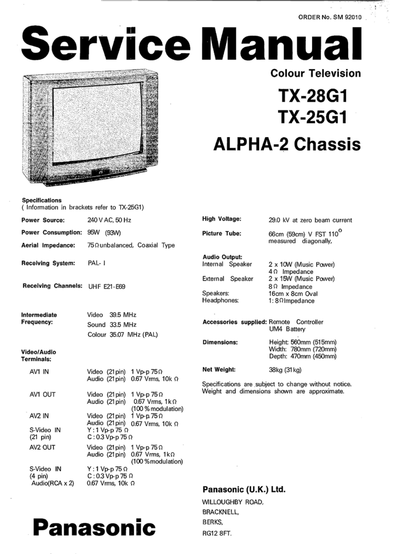
Tint
PANA
-
07550
ORDER
NO.
SM—95027
Service
Manual
Specifications
Power
Source
:
Power
Consumption
:
Aeriat
Impedance
:
Receiving
System
:
Receiving
Channels
:
VHF
H1
~
H2
(ITALY)
VHF
Rt
~
R2
VHF
Re
~
RI2
CATV
(S01
—
805)
CATV
S11
~
$20
(Ut
~
U10)
Intermediate
Frequency
:
Video
Sound
Colour
Video
/
AudioTerminals
:
AVTIN
AV1
OUT
AV2IN
AV2
OUT
AVS
IN
High
Voltage:
Picture
Tube
:
Visible
screen
size:
Audio
Output
Internal
Speaker
Headphones
Accessories
supplied
:
220
—
240
V
AC,
50Hz
o7w
75@
unbalanced,
Coaxial
Type
PAL
B/G,
D/K
PAL
~
60
SECAM
B/G,
D/K
VHF
E2
-
E12
VHF
A
—
H
(ITALY)
VHF
R3
—
RS
UHF
E21
-
E69
CATV
St
-
S10
(Mt
=
M10)
CATV
S21
-
S41
(HYPERBAND)
98.9MHz
33.4MHz,33.16MHz
32.4MH2,33.05MHz
38.07MHz,34.47MHz,34.5MHz
Video
(24
pin
)
1
Vp-p
752
Audio
(21
pin)
500
mV
rms
10k
RGB
(21
pin)
Video
(2%
pin
)
1
Vp-p
752
‘Audio
(21
pin)
500
mV
rms
1k
Video
(21
pin
)
1
Vp-p
752
Audio
(21
pin
)
600
mV
rms
10
k2
S-Video
IN
Y:1
Vp-p
752
(21
pin)
C:0.3
Vp-p
752
Video
(21
pin
)
1
Vp-p
752
Audio
(21
pin
}
500
mV
rms
1k
Selectable
output
(21
pin}
S-Video
IN
:1Vp=p
75Q
(4-pin)
€:03
Vp-p
752
Audio
(RCA
x
2)
800
mV
rms
10kK2
Video
(RCA
x
1)
1
Vp=p
752
28
KV
+
1kV
at
zero
beam
current
AGBECFA0X12
660m
2.x
15
W
(Music
Power)
4-8
Q
Impedance
1x8Q
Impedance
Remote
Control
Re
(UM3)
Battery
Colour
Television
EURO-—2
Chassis
Technische
Daten
Netzpannung:
Leistungsaufnahme
:
Antennenimpedanz:
Emptangssystem
:
Empfangsbereiche
:
VHF
H1
—
H2
(ITALY)
VHF
R1
-
R2
VHF
R6
~
R12
CATV
(S01
-
S05)
CATV
S11
~
$20
(UI
—
U10)
Zwischenfrequenz:
Video
Sound
Colour
Video
/
Audio
Anschilsse
:
AVI
EINGANG
AV1
AUSGANG
AV2
EINGANG
AV2
AUSGANG
AVS
EINGANG
Hochspannung
Bildrohre
:
Visuelle
Diagonale
:
‘Ton
Ausgangsleistung
:
Einbaulautsprecher
Kopthérer
Mitgel.
Zubehor
220
-
240
V
AC,
SOHz.
o7w
759
asymmetrisch,
Koaxial—
Typ
PAL
BIG,
D/K
PAL
—
60
SECAM
B/G,
D/K
VHF
E2
-
€2
VHF
A
—
H
(ITALY)
VHF
RS
~
RS
UHF
E21
—
E69
CATV
St
—
S10
(M1
—
M10)
CATV
$21
—
S41
(HYPERBAND)
38.9MHz
33.4MHz,33.16MHz
92.4MHz,33.05MHz
35.07MHz,34.47MH2,34,5MHz
Video
(21
pin)
1
Vp~p
752
Audio
(21
pin
)
500
mV
rmstOkQ
RGB
(2%
pin)
Video
(21
pin
)
1
Vp-p
752
Audio
(21
pin)
500
mV
rms1kQ
Video
(21
pin)
1
Vp=p
7582
Audio
(21
pin
)
800
mV
rms
10
k@
S-Video
IN
Y:
1
Vp~p
752
(21
pin)
:0.3.
Vp-p
752
Video
(21
pin)
1
Vp-p
752
Audio
(21
pin
)
00
mV
rmstk@
Selectable
output
(21
pin)
S-Video
IN
Y:1Vp~p
75
(4-pin)
€:0.3
Vp-p
752
Audio
(RCA
x
2)
500
mV
Fms10k2
Video
(RCA
x
1)
1
Vp~p
75Q
28
KV
+
1kV
bei
Nullstrahistom
AGGECF40X12
66cm
2x
15W
(Musikleistung)
4-8
Q
Impedanz
4x8
Qimpedanz
Fernbedienung
Re
(UMS)
Batterien
Dimensions
:
Height:
S82mm
Abmessungen
:
Héhe:
582mm
Width
:
752mm
Breite:
|
752mm.
Depth:
462mm
Tiefe:
462mm
Net
Weight
32kg
Gewicht
32kg
Anderungen
der
technischen
Daten
vorbehalten.
Specifications
are
subject
to
change
without
notice.
Gewichte
und
Abmessungen
sind
Naherungsangaben.
Weight
and
cimensions
shawn
are
approximate.
Panasonic
7350
LEAKAGE
CURRENT
HOT
CHECK
a
Plug
the
AC
cord
directly
into
the
AC
outlet.
Do
not
use
an
isolation
transformer
for
this
check.
28L
MESSUNG
DES
KRIECHSTROMS
IM
EINGESCHALTETEN
ZUSTAND
1.
Den
Netzstecker
direkt
in
eine
Netsteckdose
stecken.
Fir
2.
Connect
a
2kQ
10W
resistor
in
series
with
an
exposed
diese
Messung
keinen
Trenntransformator
verwenden.
metallic
part
on
the
receiver
and
an
earth
such
as
a
water
2.
Einen
2k
Q
/
10W-Widerstand
in
Serie
mit
einem
von
pipe.
auBen
zuganglichen
Metallteil
am
Fernsehgerat
und
einer
3.
Use
an
AC
voltmeter
with
high
impedance
to
measure
the
guten,
Erdung
z.B
Wasserleitung,
anschlieBen.
potential
across
the
resistor.
3.
Ein
Wechselstrom—Voltmeter
mit
einem
MeBbereich
von
4,
Check
each
exposed
Metallic
partand
check
the
voltage
at
1000
Ohm.Volt
oder
gréBer
verwenden,
um
die
Spannung
each
point.
Uber
den
Widerstand
zu
messen.
8.
Reverse
the
AC
plug
at
the
outlet
and
repeat
each
of
the
4.
Jedes
zugangliche
Metaltteil
priifen,
und
an
jedem
Punkt
above
measurements.
‘
die
Spannung
messen.
6.
The
potential
at
any
point
should
not
exceed
1.4
Vrms.
In 5.
Den
Netztecker
umgekehrt
in
die
Steckdose
stecken
und
case
ameasurementis
outside
the
limits
specified,
thereis
jede
der
obigen
Messungen
wiederholen.
a
possibility
of
a
shock
hazard,
and
the
receiver
should
be
6.
Die
Spannung
darf
an
keinem
der
Punkte
1.4V
eff.
repaired
and
rechecked
before
it
is
returned
to
the
Uberschreiten.
Wird
dieser
Wert
nicht
eingehalten,
besteht
customer.
die
Gefahr
eines
elektrischen
Schiages,
und
das
Fernsehgerat
sollte
daher
repariert
und
nachgepriift
HOT
CHECK
CIRCUIT
7
werden,
bevor
es an
den
Kunden
zuriickgegeben
wird.
SCHALTUNGSAUFBAU
FUR
PRUFUNG
IM
EINGESCHALTETEN
ZUSTAND
RONTGENSTRAHLUNG
A.C.
VOLTMETER
WECHSELSTROM—VOLTMETER
ACHTUNG
:
1.
Potentielle
Quellen
von
Rédntgenstrahlung
—
in
TO
INSTRUMENT'S.
oS
Fernsehgeraten
sind
das
Hochspannungsteil
und
die
EXPOSED
Bildrohre.
METALLIC
PARTS
jy
|
2.
Bei
Verwendung
eines
BildrGhren—Prifgerates
fur
den
Service
ist
sicherzustellen,
daB
es
flr
die
Belastung
von
Oars
ore
Water
Pipe
29kV
geeignet
ist,
ohne
daB
eine
Réntgenstrahlung
‘TV-GERATES
(Earth)
verursacht
wird.
2K
ohm
10W
bg
ens
(ercuna)
ANMERKUNG
:
Es
ist
wichtig,
da8
ein
prazises,
regelmasig
Fig.
gepriftes
Voltmeter
verwendet
wird.
Abb.1
1.
Helligkeit
auf
Minimum
stellen.
-
=
Die
Hochspannung
messen.
Die
Anzeige
des
X-RADIATION
WARNING
Instrumentes
sollte28kV
+t
1kVbetragen.
FallsdieAnzeige
te
The
potential
sources
of
X—Radiation
in
TV
sets
are
the
diese
Toleranzgrenzen
iberschreitet,
ist
die
sofortige
high
voltage
section
and
the
picture
tube.
Behebung
nétig,
um
die
.
Méglichkeit
vorzeitigen
2.
Whenusingapicturetubetestjigfor
service
ensure
thatthe
Komporentensuetal's
au
verhiten.
jig
is
capable
of
handling
29kVwithout
causing
3.
Um
die
Méglichkeit
von
Rontgenstrahlung
zu
begrenzen,
X-Radiation.
NOTE
:
It
is
important
to
use
an
accurate
periodically
calibrated
high
voltage
meter
ft;
Set
the
brightness
to
minimum.
2.
Measure
the
high
voltage.
The
meter
should
indicate
28kV
+
ikV
if
the
meter
indication
is
out
of
tolerance,
immediateservice
and
correctionis
requiredto
preventthe
possibility
of
premature
component
failure.
3.
Topreventany
X—Radiation
possibility,
itis
essentialtouse
the
specified
tube.
ist
es
wichtig,
da8
nur
die
vorgeschriebene
Bildrdhre
verwendet
wird.
|
TX
—
28LD1C
LOCATION
OF
CONTROLS
LAGE
DER
EINSTELLREGLER
Gon)
a
iss
Gon
-f
|
\
|
FOCUS
\
ro
FOKUSREGLER
i
OF
SCREEN
ee
‘SCHIRMGITTERREGLER
Fig.2
Abb.2
SERVICE
HINTS
SERVICE
HINWEISE
HOW
TO
REMOVE
THE
REAR
COVER
ENTFERNEN
DER
GERATERUCKWAND
18
Remove
the
6
screws
(A)
as
shown
in
Fig.3/Fig.4.
1.
Die
6
Schrauben
(A)
entfernen,
siehe
Abb.3/Abb.4.
S
@
SCREW
SCHRAUBEN
Fig.4
Abb.4
SCREWS
(A)
SCHRAUBEN
A
ADbS.
ADJUSTMENT
PROCEDURE
The
remote
control
is
used
for
entering
and
storing
adjustments,
with
the
exception
of
cut—off
adjustments
which
must
always
be
done
prior
to
service
adjustment.
Perform
adjustments
in
accordance
with
screen
display.
The
display
on
the
screen
also
specifies
the
CCU
variants
as
well
as
the
approx.
setting
values.
The
adjustment
sequence
for
the
service
mode
is'indicated
below.
1.
2.
Set
the
Bass
to
maximum
position,
set
the
Treble
to
minimum
position,
press
the
F
button
followed
by
the
volume
down
button
on
the
customer
controls
at
the
front
of
the
TV
and
at
the
same
time
press
the
Reveal
button
on
the
remote
control,
this
will
place
the
TV
into
the
Service
Mode.
Press
the
RED
/
GREEN
buttons
to
step
up
/
down
through
the
functions.
3.
4.
5.
TX
—
28L
Press
the
YELLOW
/
BLUE
buttons
to
alter
the
function
values.
Press
the
STORE
button
after
each
adjustment
has
been
made
to
store
the
required
values.
To
exit
the
Service
Mode
press
the
Normalisation
button..
NOTE:
This
TV
also
has
the
option
of
using
a
Memory
Pack
which
enables
you
to
copy
the
preset
TV
channels
into
the
Memory
Pack
and
then
download
them
onto
this
or
any
other
EURO~2
TV
set.
TV
to
Memory
Pack
process
1.
Plug
the
memory
pack
into
the
lower
of
the
two
21
pin
terminals
at
the
back
of
the
TV
and
switch
the
TV
on.
If
the
TV
has
only
one
21
pin
connector
then
this
will
be
able
to
accept
the
memory
pack.
2.
Go
into
the
Service
Mode
as
explained
above.
The
screen
will
show:
—
Program
External>
>TV
3.
Press
the
blue
button
ontheremote
control.
Thescreen
will
show:
—
Program
TV>>External
4.
Press
the
STORE
button
on
the
TV.
The
screen
will
show:
—
Storing
5.
All
the
tuning
information
stored
inside
the
TV
will
now
be
transferred
tothe
Memory
Pack.
This
process
willtake2—3
minutes
to
complete
and
when
finished
the
screen
will
show:
—
Ok!
Errors
Memory
Pack
to
TV
Process
fie
Plug
the
memory
pack
into
the
lower
of
the
two
21
pin
terminals
at
the
back
of
the
TV
and
switch
the
TV
on.
Ifthe
TV
has
only
one
21
pin
connector
then
this
will
be
able
to
accept
the
memory
pack.
Go
into
the
Service
Mode
as
explained
above.
The
screen
will
show:—
Program
External>
>TV
Press
the
STORE
button
on
the
TV.
The
screen
will
show:—
Loading
All
the
tuning
information
stored
inside
the
Memory
Pack
will
now
be
transferred
to
the
TV.
This
process
willtake
2-3
minutes
to
complete
and
when
finished
the
screen
will
show:
—
OK!
The
tuning
information
from
the
Memory
Pack
has
now
been
copied
into
the
TV
To
exit
from
the
Service
Mode
press
the
Normalisation
button.
The
process
has
now
been
completed
and
the
Memory
Pack
can
now
be
removed.
If
an
error
occurs
while
using
the
Memory
Pack
the
TV
will
detect
this
and
the
screen
will
show:
~
Program
lfthis
happens
then
press
the
Normalisation
button
and
repeat
the
process
that
was
being
used.
Ifthe
errors
continue
to
occur
then
check
the
connectors
between
the
TV
and
the
memory
pack
and
check
the
9V
battery
inside
the
memory
pack.
TX
—
28LD1C
ABGLEICHVERFAHREN
Die
Fernbedienung
dient
zum
Eingeben
und
Abspeichern
der
Einstellwerte,
mit
Ausnahme
der
Sperrpunkteinstellung,
die
grundsaitzlich
vor
den
hier
beschriebenen
Einstellungen
vorgenommen
werden
muss.
Die
Einstellung
erfolgt
entsprechend
dem
Bildschirm—Display.
Auf
dem
Bildschirm—Display
erscheinen
auch
die
CCU—Varianten
sowie
die
ungefahren
Einstellwerte.
Die
Einstelifolge
fir
den
Service—Modus
ist
nachstehend
beschrieben.
a
1.
Den
Tiefenregler
auf
Héchstellung
und
den
Héhenregler
3.
Mit
der
GELBEN
und
BLAUEN
Taste
die
Werte
der
auf
Mindeststellung
stellen.Nachdem
die
F—Taste
am
einzeinen
Funktionen
andern.
Bedienfeld
des
FS
—Gerates
gedriicktwurde,
die
Die
Taste
4.
Nach
jeder
Einstellung
die
Taste
STR
auf
der
”Lautstarke
Minus”
amFS—Geratdriickenund
gleichzeitig
Fernbdienung
oder
am
Bedienfeld
driicken,
um
die
die
Taste
"Reveal”
auf
der
Fernbedienung
betatigen.
geanderten
Werte
abzuspeichern.
Hierdurch
wird
das
FS—Gerat
auf
Service-Modus
5.
ZumVerlassendes
Service—Modus
die
N”—Tasteaufder
geschaltet.
2.
Die
einzelnen
Funktionen
mit
Hilfe
der
ROTEN
und
GRUNEN
Taste
anwahlen.
HINWEIS:
Dieses
FS—Gerat
bietet
auch
die
Maglichkeit
eines
Memory
Pack,
mit
dem
Sie
die
gewahlten
Fernsehkandale
abspeichern
und
auf
jedes
beliebige
EURO2
FS—Gerat
umkopieren
kénnen.
Fernbdienung
driicken
Kopieren
der
Einstelldaten
vom
FS—Gerat
in
das
Memory
Kopieren
der
Einstelldaten
vom
Memory
Pack
in
das
Pack
FS-Gerat
a
Das
Memory
Pack
in
die
untere
der
beiden
21—poligen
1.
Das
Memory
Pack
in
die
untere
der
beiden
21—poligen
Steckerleisten
an
der
Riickseite
des
FS—Gerats
stecken
Steckerleisten
an
der
Riickseite
des
FS—Gerats
stecken
und das
Gerat
einschalten.
Wenn
das
FS—Gerat
nur
eine
und
das
Gerat
einschalten.
Wenn
das
FS—Gerat
nur
eine
21—polige
Anschlussleiste
hat,
kann
das
Memory
Pack
21—polige
Anschlussieiste
hat,
kann
das
Memory
Pack
auch
an
diese
angeschlossen
werden.
auch
an
diese
angeschlossen
werden.
2.
Wie
schon
oben
beschrieben
auf
Service~Modus
2.
Wie
schon
oben
beschrieben
auf
Service—Modus
umschaiten.
Auf
dem
Bildschirm
erscheint:
umschaiten.
Auf
dem
Bildschirm
erscheint:
Program
Program
External>
>TV
External>>TV
3.
Nun
die
blaue
Taste
an
der
Fernbedienung
betatigen.
Auf
3.
Die
Taste
STORE
am
Fernseher
drticken.
Der
Bildschirm
dem
Bildschirm
erscheint:
meldet
nun:
Program
i
TW>
external
Loading
4.
Die
Taste
STORE
am
Fernseher
drucken.
Der
Bildschirm
4.
Die
im
Memory
Pack
abgespeicherten
Einstelldaten
meldet
nun:
werden
nun
in
das
FS—Gerat
tberspielt.
bei
aggeschlossener
Datentibertragung
meldet
der
Storing
Bildschirm:
5.
Die
im
FS—Gerat
abgespeicherten
Kanal—Einstelldaten
OK!
werden
nun
in
das
Memory
Pack
itiberspielt.
bei
abgeschlossener
Datentibertragung
meldet
der
5.
Die
Kanal—Einstelidaten
sind
damit
vom
Memory
Pack
in
Bildschirm:
das
FS—Gerat
iiberspielt.
6.
ZumVerlassen
des
Service—Modus
die
”N”—Taste
aufder
OK!
Fernbdienung
driicken
he
Der
Kopiervorgang
ist
somit
abgeschlossen,
und das
Memory
Pack kann
von
der
Steckerleiste
abgezogen
werden.
,
Fehler
Falls
beim
Gebrauch
des
Memory
Packs
Fehler
autreten,
zeigt
das
FS—GerAt
dies
auf
dem
Bildschirm
mit
der
folgenden
Meldung
an:
Program
Error!
In
diesem
Fall
muss
der
Service—
Modus
durch
Driicken
der
”N”
—Taste
auf
der
Fernbedienung
verlassen
und
anschliessend
der
Vorgang
wiederholt
werden.
Falls
weiterhin
Fehlermeldungen
erscheinen,
mUissen
die
Anschlusskontakte
zwischen
FS—Gerat
und
Memory
Pack
sowie
die
9V
Batterie
im
Memory
Pack
kontrolliert
werden.
ADJUSTMENT
PROCEDURE
Item/Preparation
Adjustments
+8
SET-UP
Recieve
a
window
pattern
1.
Set
the
+B
voltage
up
as
follows:
Bs
Set
the
controls:
pale
R811
so
that
B2
shows
147V
+
1V
Brightness
minimum
Confirm
the
following
voltages.
Contrast
minimum
a
203
+
10V
BE
12
+
05V
Volume
minimum
B3
27
+
1V
B7
5
+
0.1/-0.25V
B4
355+
WV
BB
5
+
0.25V
B5
155+
WV
u33-
31
+
1
i
RF
AGC
te
Receive
a
test
pattern.
A,
Check
that
the
noise
becomes
large
when
the
RF
AGC
VR
2.
Connect
an
oscilloscope
between
the
R126
is
turned
counterclockwise.
After
the
check
turn
it
clockwise.
tuner
RF
AGC
and
ground.
2.
Gradually
turn
the
RF
AGC
VR
anti-clockwise,
and
set
the
3.
Set
the
oscilloscope
gain
range
to
RF
AGC
VR
to
the
point
where
the
RF
AGC
voltage
is
just
falling
toa
1Vidiv.
point
where
this
voltage
drops
by
0.2V
from
the
maximum
value.
CUT
OFF
it
Receive
a
widow
pattern.
1.
Confirm
then
value
is
128
and
select
Ug2
mode
noting
colour
with
2.
Degauss
the
tube
externally.
largest
value
3.
Set
the
TV
into
Service
Mode
1.
2.
Turn
the
screen
VR
until
a
colour
reaches
20~
30.
*
Select
Cutoff
DC
mode.
3.
Connect
an
oscilloscope
to
the
cathode
with
the
biggest
value
colour.
4.
Select
Cutoff
DC
mode
and
adjust
Cutoff
pulse
to
159V
+/—
5V.
5.
Disconnectthe
oscilloscope
and
adjustthe
screen
to
whichever
colour
reaches
50
+/—
10
first.
ABGLEICH
|
Vorbereitung
Abgleich
+B
—
Abgleich
1.
Testbild
empfangen.
1.
Mit
R611
muB
die
B2
auf
147V
+
1V
eingestelit
werden.
2.
Helligkeit
auf
Minimum
2.
Folgende
Spannungen
sind
zu
Uberpriifen
:
Kontrast
auf
Minimum
B1
203
+
10V
BE
12
+
05V
Lautstarke
auf.
=
Minimum
B3
27
+
1v
B7
5
+
0.1/-0.25V
B4
355+
iV
Bs
5
+
0.25V
BS
155+
1Vv
U33
314
IV
RF
AGC
1.
Testbild
empfangen.
Ts
Wenn
das
Poti
R126
(RF
AGC)
gegen
den
Uhrzeigersinn
gedrehtwird.
2.
An
die
Tuner
RF
AGC
und
Masse
ein
muB
das
Rauschen
zunehmen.
Oszilloskop
anschileB.
2.
Das
Poti
R126
gegen
den
Uhrzeigersinn
so
einstellen,
daB
die
3.
Die
Empfindlichkeit
des
Oszilloskopes
aut
eingestelite
Spannung
um
0,2V
unter
dem
Maximalwert
1V/div.
einstellen.
CUT
OFF
te
Im
Feld
Cutoff
DC
mu8
der
Wert
128
stehen,
Im
Ugz—Feld
muB
Farbe
+.
Testbild
empfangen.
mit
dem
héchstem
Wert
notiert
werden.
2
Bildrohre
entmagnersicrert
2.
Mit
dem
Screen—Poti
wird
die
Farbe
auf
20
bis
30
eingestellt.
3.
Service~Mode
1
anwahlen.
3.
An
die
Kathode
mit
den
héchsten
Wert
(aus
Punkt
1)
wird
ein
4
Im
Service—Moade
den
Abgleichpunkt
Oszilloskop
angeschlossen.
Cutoff
DO-Mode
wahien
(14).
4.
Im
Cutoff
DC
Mode
wird
der
Cutoff—Puls
auf
159V
+
5V
eingestelit.
5.
Das
Oszilloskop
entfermen
undim
CutoffMode
die
Werte
so
einstellen,
dafsie
alle
bis
50
+
10
liegen.
a
ALIGNMENT
SETTINGS
(The
figures
used
below
are
nominal
and
used
for
representative
purposes
only)
Settings
/
Special
features
—_]
Alignment
Function
1.
Vertical
amplitude
3.
Vertical
linearity
Optimum
setting
il
4.
Vert.
DC.
000
Not
to
be
adjusted.
5.
V—-Pos
\V.
Pos.
905,
Optimum
setting
6.
Horizontal
amplitude
7.
Horizontal
position
8.
Text
Position
H-AMP
H-POS
061
j
Optimum
setting
ea
|___
TEXT
POSITION
i
Optimum
setting
9.
EW
-amplitude
Optimum
setting
ta
10.
EW-—amplitude
Optimum
setting
11.
Trapezium—comp
12.
Trapezium—comp
|
aie
4
Optimum
setting
Optimum
setting
13.
Colour
VCO
Press
either
Blue
or
Yellow
buttons
to
effect
automatic
adjustment
14.
Cut-off
DC
Cut-off
DC
J
171
Not
to
be
adjusted.
15.
Ug2
Test
16.
Cutoff
|
006
ta
“Ug
2
Test
wie)
055
Select
Cutoff
DC
in
Service
Mode mode
and
confirm
the
value
is
128.
Select
Ug
2
Test
noting
colour
with
largest
value,
adjust
on
FBT
until
a
colour
reaches
20
~
30.
Connect
an
oscilloscope
to
the
cathode
of
the
biggest
value
colour,
select
Cutoff
DC
mode
and
adjust
get
Cutoff
pulse
voltage
to
159+5V.
Disconnect
the
oscilloscope
and.adjust
the
screen
to
whichever
colour
reaches
50=10
first.
_|
034
Press
the
GREEN
button
to
step
through
the
settings.
Adjust
for
optimum.
17.
White
Press
the
GREEN
button
to
step
through
the
settings.
Adjust
for
optimum.
ABGLEICHTABELLE
(Die
angegebenen
Werte
sind
Mittelwerte
und
Konnen
individuell
nach
oben
oder
unten
nach
dem
korrekten
Abgleich
abweichen)
Abgleichfunktion
1.
Vertikale
Amplitude
ile
Einstellung/Besondere
Merkmale
2.
Vertikale
symmetrie
3.
Vertical
linearitat
+
Optimale
Einstellung
2
4.
Vert.
DC
Nicht
einstellen
—
5.
V—Pos
Optimale
Einstellung
—
Horizontale
position
8.
Text
Position
TEXT
POSITION
|
048,
=
Optimale
Einstellung
Optimate
Einstellung
9.
OW
-amplitude
Optimale
Einstellung
10.
OW-amplitude
Optimale
Einsteliung
11
Trapez—Kompensation
ae
TRAPEZ—1
Optimale
Einstellung
047
12.
Trapez—Kompensation
aoe
Optimate
Einstellung
43.
Colour
VCO
aes
Optimate
Einstellung
SN
I
14,
Cut-off
DC
15.
Bildschirm
16.
Cutoff
17.
White
ee
Cut-off
DC
171
Wahien
Sie
den
Cutoff
DC
Im
Service
Mode
und
Ug
2
Test
006 055 059
Nicht
einstellen
bestatigen
Sie
den
Wert
128.
Im
Ug2—Feld
muB
die
Farbe
mit
dem
héchsten
Wert
notiert
werden.
Mit
dem
Screen—Poti
wird
die
Farbe
auf
20
bis
30
eingesteilt.
An
die
Kathode
mit
den
héchsten
Wert
(aus
Punkt
1)
wird
ein
Oszilloskop
angeschlossen.
Im
Cutoff
DC
Mode
wird
der
Cutoff—Puls
auf
159V
+
5V
eingestellt.Das
Oszilloskop
entfermen
und
im
Cutoff
Mode
die
Werte
so
einstellen,
daSsie
alle
bis
50
+
10
liegen.
Cutoff
034
052 056
White
216
255
216
Die
Einstellungen
mit
Hilfe
der
GRUNEN
Taste
anwabhlet
ale
Einstellung
Die
Einstellungen
mit
Hilfe
der
GRUNEN
Taste
anwahlen.
Optimale
Einstellung.
|
TX
—
28L
SELF
CHECK
Self
check
is
used
to
automatically
check
the
Bus
Lines
and
Hexadecimal
code
of
the
TV
set.
To
getinto
the
Self
Check
mode
press
the
F
button
followed
by
the
volume
down
button
on
the
customer
controls
atthefront
ofthe
TV
at
the
same
time
pressing
the
Status
button,
on
the
Remote
Control,
and
the
screen
will
show:
—
4
——
ok
|
Tuner
Dalby
ic
2
—
ok
|
VF PS
MODE
3
—
ok
|
EEPROM
PTAO
4
—
——
|
Soundav
PTAt
5
—
«
|
eh
rms
6
—~
ok
|
voP
PTAS
7
—
oo
TPU
PSDA
8
——
ok
MsP
PSCLt
g
—
——
|
Dolby
sub
PSCLa
10
—
_
—
|
Robyic
PSCL4
lf
the
CCU
ports
have
been
checked
and
found
to
be
incorrect
then
”——”
will
appear
in
place
of
"OK”.
Hex
codes
PSBLED
7A
P
OFF
20
62
P
DEFL
es
PRAM
85
10
SELBSTDIAGNOSE
1)
Die
Selbstdiagnose
dient
zum
automatischen
Priifen
der
Bus—Leitungen
sowie
des
Hexadezimalcodes
des
FS—Gerats.
Zum
Umschalten
auf
Selbstdiagnose
nach
dem
Driicken
der
*“F’~Taste
die
"Lautstérke
Minus”
Taste
am
Bedienfeld
des
FS-Gerats
und
gleichzeitig
die
Taste
"Status”
an
der
Fernbedienung
driicken;
auf
dem
Bildschirm
erscheint
hierauf:
—
2)
Nach
der
Selbstdiagnose
wird
das
Ger&t
automatisch
auf
samtliche
werksseitigen
Standardeinstellungen
zurtickgesetzt.
Dolby
Ic
Tuner
eee
2F—Verstarker
PS
MODE
EEPROM
P
TAO
Audio
PTA
AV—Schalter
1
Video
AV
PTA2
switcht
Video
PTAS
AV-Schalter
1
Video
PSDA
AV-Schaiter
2
MsP
P
scl
Dolby
Sub
PScLs
Dolby
IC
Re
Ph
PSCLé
Wenn
der
Hauptprozessor
(CCU)
an
den
Anschltissen
einen
Fehler finden
sollte,
oder
der
Anschluss
nicht
beiegt
ist,
zeigt
die
entsprechende
Position
— —
anstelie
von
OK
an.
Hexadezimalcode
PSBLED
fe
P
OFF
2
62
P
DEFL
54
PRAM
Bs
CONDUCTOR
VIEWS
ANSICHT
DER
LEITERBAHNEN
E
—
BOARD
TNP197091
ie
fg,
7a
ca0dig
SEE
REVERSE
FOR
Frage
C1
9601
Rana
051
6
8)
FP
8
Z
:
ey
a
‘2
J
itt
go.
oo
Bo
G8:
cee
Geog
3
ee
We
atc
8)
61212
1206;
fase
oe
ME
BB
brat!
TX
—
281
|
TRANSISTORS:
[biowe
s
O25"
ca
16851
ea)
B)
TC105T
AB)
Te1207
161208
E5
HS
|
Dasa
Em
161205
Ba
[aati
[D853
Teta08
Az
fes502
ES
|
045i
Dass
He
[D203
Gt
[D1204
1203,
a
ja1204
C4
(Q1205,
6
NEY:
4
SSNS:
‘1206
D6
De
208.
83
11

Other Panasonic TV manuals

Panasonic TX-32PS11D User manual

Panasonic

Panasonic TX-32PS11D User manual

Panasonic CT27SX11E - 27" COLOR TV User manual

Panasonic

Panasonic CT27SX11E - 27" COLOR TV User manual

Panasonic VIERA TC-P46S2 User manual

Panasonic

Panasonic VIERA TC-P46S2 User manual

Panasonic TX-28MD4C User manual

Panasonic

Panasonic TX-28MD4C User manual

Panasonic TX-43JX600B User manual

Panasonic

Panasonic TX-43JX600B User manual

Panasonic Viera TH-37PW5 User manual

Panasonic

Panasonic Viera TH-37PW5 User manual

Panasonic TX-28MD4P User manual

Panasonic

Panasonic TX-28MD4P User manual

Panasonic TX-W32R4 User manual

Panasonic

Panasonic TX-W32R4 User manual

Panasonic TX-W28R4F User manual

Panasonic

Panasonic TX-W28R4F User manual

Panasonic TX-36PF10P User manual

Panasonic

Panasonic TX-36PF10P User manual

Panasonic TH-P42G15A User manual

Panasonic

Panasonic TH-P42G15A User manual

Panasonic TX-21S4TP User manual

Panasonic

Panasonic TX-21S4TP User manual

Panasonic TH-42AS700A User manual

Panasonic

Panasonic TH-42AS700A User manual

Panasonic TX-29AS10C User manual

Panasonic

Panasonic TX-29AS10C User manual

Panasonic TX-W28R3F User manual

Panasonic

Panasonic TX-W28R3F User manual

Panasonic TX-22LT2F User manual

Panasonic

Panasonic TX-22LT2F User manual

Panasonic TX-29P190T User manual

Panasonic

Panasonic TX-29P190T User manual

Panasonic TX-55CRW434 User manual

Panasonic

Panasonic TX-55CRW434 User manual

Panasonic Viera TH-32LRG20B User manual

Panasonic

Panasonic Viera TH-32LRG20B User manual

Panasonic Viera TH-37PW5 User manual

Panasonic

Panasonic Viera TH-37PW5 User manual

Panasonic Viera TH-42PZ700 User manual

Panasonic

Panasonic Viera TH-42PZ700 User manual

Panasonic TC-14Z88RQ User manual

Panasonic

Panasonic TC-14Z88RQ User manual

Panasonic CT-36SX32 User manual

Panasonic

Panasonic CT-36SX32 User manual

Panasonic Viera TH-40CS610A User manual

Panasonic

Panasonic Viera TH-40CS610A User manual

Popular TV manuals by other brands

Princess 68CT8 owner's manual

Princess

Princess 68CT8 owner's manual

Sony KD-65S8500C reference guide

Sony

Sony KD-65S8500C reference guide

JVC AV-32H35SAE instructions

JVC

JVC AV-32H35SAE instructions

Philips/Magnavox TV user guide

Philips/Magnavox

Philips/Magnavox TV user guide

Sony Trinitron KV-PF14L7J Service manual

Sony

Sony Trinitron KV-PF14L7J Service manual

Samsung HL-R4667W - 46" Rear Projection TV Owner's instructions

Samsung

Samsung HL-R4667W - 46" Rear Projection TV Owner's instructions

Samsung UE43KU6500U user manual

Samsung

Samsung UE43KU6500U user manual

Toshiba 43S7DE Service manual

Toshiba

Toshiba 43S7DE Service manual

Philips TV quick start guide

Philips

Philips TV quick start guide

Sharp cx68n5 Operation manual

Sharp

Sharp cx68n5 Operation manual

Sony Bravia XBR-65X750D reference guide

Sony

Sony Bravia XBR-65X750D reference guide

Tech Line TL-37LC735 Operating	 instruction

Tech Line

Tech Line TL-37LC735 Operating instruction

JVC AV-20320, AV-20321, C-20310, C-13310,... user guide

JVC

JVC AV-20320, AV-20321, C-20310, C-13310,... user guide

Grundig 26 LXW 68-8600 DL user manual

Grundig

Grundig 26 LXW 68-8600 DL user manual

Telefunken TKP2939ST Service manual

Telefunken

Telefunken TKP2939ST Service manual

Sanyo CP28WF1 Service manual

Sanyo

Sanyo CP28WF1 Service manual

Apex Digital AT2408S, AT2708S instruction manual

Apex Digital

Apex Digital AT2408S, AT2708S instruction manual

Sony BRAVIA XR Setup guide

Sony

Sony BRAVIA XR Setup guide

manuals.online logo
manuals.online logoBrands
  • About & Mission
  • Contact us
  • Privacy Policy
  • Terms and Conditions

Copyright 2025 Manuals.Online. All Rights Reserved.