manuals.online logo
Brands
  1. Home
  2. •
  3. Brands
  4. •
  5. Panasonic
  6. •
  7. VCR System
  8. •
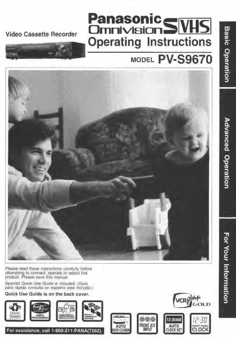
  9. Panasonic Omnivision PV-S7670 User manual

Panasonic Omnivision PV-S7670 User manual

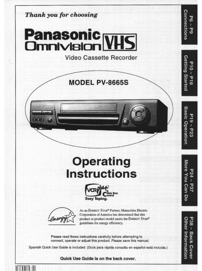
Thank
you
for
choosing
Panasonic
Omnivision
MODEL
PV-S7670
Video
Cassette
Recorder
f
CÈ!
Box
ontrol
Easy
Taping.
Operating
Instructions
Please
read
these
instructions
carefully
before
attempting
to
connect,
operate
or
adjust
this
product.
Save
this
manual.
Spanish
Quick
Use
Guide
is
included.
(Guía
para
rápida
consulta
en
español
está
includo.)
Quick
Use
Guide
is
on
the
back
cover.
VQTS3325
(A)
suopəuuoy
pəues
Buiyje5
8ld
~
Old
Edd
~
6ld
uonelado
29.seg
Od
UBD
NOA
JOIN
S€d
A
UOI]JEULIOJU]
ETTO)
1309
YIP
~
Ed
Things
You
Should
Know
Congratulations
Date
of
Purchase
on
your
purchase
of
one
of
the
most
sophisticated
and
Dealer
Purchased
From
reliable
products
on
the
market
today.
Used
properly,
Dealer
Address
it
will
bring
you
and
your
family
years
of
enjoyment.
Dealer
Phone
No.
Please
fill
in
the
information
at
right.
The
serial
number
Model
N
Cee
ee
TAN
is
on
the
tag
located
on
the
back
of
your
VCR.
odelNo._______PV-S7670
___
ç
_—
Safety
Precautions
Serial
No.
Warning:
To
prevent
fire
or
shock
hazard,
do
not
expose
this
equipment
to
rain
or
moisture.
This
video
recorder,
equipped
with
the
e
is
compatible
with
existing
VHS
equipment.
Only
use
those
tapes
with
the
[VHS
or
mark.
It
is
recommended
that
only
cassette
tapes
that
have
been
tested
and
inspected
for
use
in
2,
4,
6,
and
8
hour
VCR
machines
be
used,
This
video
recorder
is
equipped
with
recording
functions
for
both
conventional
yus
and
SVHS
systems
to
enable
users
to
select
either
mode.
An
cassette
recorded
in
the
mode
cannot
be
played
back
with
conventional
(VHS
VCRs.
FCC
Warning:
Any
unauthorized
changes
or
modifications
to
this
equipment
would
void
the
user's
authority
to
operate.
CAUTION
This
symbol
warns
the
user
that
uninsulated
voltage
within
the
unit
may
AN
A
have
sufficient
magnitude
to
cause
electric
shock.
Therefore,
it
is
dangerous
to
make
any
kind
of
contact
with
any
inside
part
of
this
unit.
CAUTION.
TO
REDUCE
THE
RISK
OF
ELECTRIC
SHOCK,
DO
NOT
REMOVE
COVER
¡OR
BACK)
This
symbol
alerts
the
user
that
important
literature
concerning
the
NO
USER
SEAVICEABLE
PARTS
INSIDE
REFER
BEAVICING
TO
QUALIFIED
SERVICE
PERSONNEL
operation
and
maintenance
of
this
unit
has
been
included.
Therefore,
it
should
be
read
carefully
in
order
to
avoid
any
problems.
Table
of
Contents
Important
Safeguards
and
Precautions
..........0....:cccsesssscsssesersreeeees
a
CE
3
Unpacking
Your
VCR
+»
Product
Features
............cccccccscccseceeccceccensceeesecsssecscececeveaersaesresenseeseey
4
VCR
and
Cassette
Information
(Record
Tab,
Tape
Speeds,
Head
Cleaning,
D.S.T.,
Specifications)
.....
5
Connections
Basic
Connection
(Antenna
and
VCR,
VCR
and
TV)......0...ccccccccscscccescecenssscecescecessceeeesecersseseeece
6,7
Additional
Connections
(CATV,
Audio/Video)
..........ccs:ccsscccsessceeecssececseecceesssesesseceseessecssseeeeetess
8,9
Getting
Started
Location
of
Controls
(Remote
Control,
VCR)
.....ccc:...ccecceesccccessceestssececessenseeuseceeessrssssseesceceens
10,
11
One
Time
VCR
Setup
(On-Screen
Language,
Cable
Box/
DSS
Receiver
Setup,
Channel
Memory,
Auto
Clock
Set).........
12~17
On-Screen
Displays
(OSD)
(Function,
Channel,
Menu,
VCR
Status
8
Clock,
Warning)
.....................
18
Basic
Operation
Playback
a
Tape
(Main
Operation,
Special
Effects,
Quality
Picture
Features)
.......ccccccccseesseseessesterees
19
Record
On
a
Tape
(Main
Operation,
One
Touch
Record,
Channel
Selection,
Select
Input
Mode)....
20,
21
Timer
Recording
(Main
Operation,
Cancel,
Clear
or
Replace
Program
Contents)
..........s:ccsscesceeees
22,23
More
You
Can
Do
Tape
Operation
(Repeat
Play,
Zero
Search,
One
Minute
Skip,
Shuttle
Search,
Auto
Functions,
Index
Search)
....
24-26
Special
VCR
Features
(VCR
Lock,
Warning
Beeper)
....oooooocccoocccnooccononononanncoono
can
no
nono
nonnnrononnanannon
27
Copying
Your
Tapes
(Dubbing)
(Connection,
Main
Operation,
Monitoring)
.........ccccscccsessscsseeesseuee.
28
ATLAS
A
A
A
29
MTS
Broadcast/
VHS
Hi-Fi
Stereo
System
(Stereo/SAP/Mono
Broadcast,
Select
Audio
Mode,
Spatializer)
...
30,
31
VCR
Plus+
Setup
(VCR
Plus+
Channel
Setup)
.........0...ccccccecscsecccesscscescccesseccesseesececsssccessecerscevsuse
32
VCR
Plus+
Programming
(Main
Operation,
Make
Correction)
........oocononncnonnconnincanccnncnccnocnnccnnonono
33
Multi-Brand
Control
Feature
oo...
cece
cccccccccsscccccsecensccecsevssssssssesseveesvscueseversestsneseccense:
34,
35
Other
Information
Before
Requesting
Service
(Self-check
items)
...........ccccccccccesesesccesscesseeseceeetsceececausecssesssersees
36,
37
SOPVICS
COR
reacia
38
A
A
O
AN
39
Spanish
Quick
Use
Guide
a
ia
ase
ios
40-43
CURS
GUO
E
A
Back
Cover
INO
AyImportant
Safeguards
and
Precautions
FOR
YOUR
SAFETY,
READ
AND
RETAIN
ALL
SAFETY
AND
OPERATING
INSTRUCTIONS.
HEED
ALL
WARNINGS
IN
THE
MANUAL
AND
ON
THE
UNIT
INSTALLATION
1
POWER
SOURCE
CAUTION
Operate
only
from
a
power
source
indicated
on
the
unit
or
in
this
manual.
If
necessary,
have
your
Electric
Utility
Service
Company
or
Video
Products
Dealer
verify
the
power
source
in
your
home.
2
POLARIZED
OR
GROUNDING
PLUG
As
a
safety
feature,
this
Video
product
comes
with
either
a
polarized
power
cord
plug
(one
blade
is
wider
than
the
other),
or
a
three-wire
grounding
type
plug.
POLARIZED
PLUG
CAUTION;
This
plug
will
only
fit
into
an
outlet
one
way.
If
you
cannot
fully
insert
the
plug,
try
reversing
it.
If it
still
will
not
fit,
have
an
electrician
install
the
proper
wall
outlet.
Do
not
defeat
the
safety
feature
by
tampering
with
the
plug.
GROUNDING
PLUG
CAUTION:
This
plug
will
only
fit
into
a
three-hole
grounding
outlet.
If
necessary,
have
an
electrician
install
the
proper
outlet.
Do
not
defeat
the
safety
feature
by
tampering
with
the
plug.
3
POWER
CORD
Make
sure
power
cords
are
routed
so
that
they
are
not
likely
to
have
anything
rest
on
them,
roll
over
them,
or
be
in
the
way
of
walking
traffic.
If
an
extension
cord
is
used,
make
sure
it
also
has
either
a
potarized
or
grounded
plug
and
that
the
cords
can
be
securely
connected.
Frayed
cords,
damaged
plugs,
and
damaged
or
cracked
wire
insulation
are
hazardous
and
should
be
replaced
by
a
qualified
service
technician.
Overloaded
outlets
and
extension
cords
are
fire
hazards
and
should
be
avoided.
4
DO
NOT
BLOCK
VENTILATION
HOLES
Ventilation
openings
in
the
cabinet
release
heat
generated
during
operation.
If
they
are
blocked,
heat
build-up
inside
the
unit
can
cause
failures
that
may
result
in
a
fire
hazard
or
heat
damage
to
cassettes.
For
protection,
follow
these
rules:
a.
Never
cover
ventilation
slots
or
the
unit
while
in
use,
or
operate
the
unit
when
placed
on
a
bed,
sofa,
rug,
or
other
soft
surface.
b.
Avoid
built-in
installation,
such
as
a
book
case
or
rack,
untess
proper
ventilation
is
provided.
5
AVOID
EXTREMELY
HOT
LOCATIONS
OR
SUDDEN
TEMPERATURE
CHANGES
Do
not
place
the
unit
over
or
near
any
kind
of
heater
or
regulator,
in
direct
sunlight,
inside
a
closed
vehicle,
etc..
Do
not
move
the
unit
suddenly
between
areas
of
extreme
temperature
variation.
If
the
unit
is
suddenly
moved
from
a
cold
place
to
a
warm
place,
moisture
may
condense
in
the
unit
and
on
the
tape.
6
TO
AVOID
PERSONAL
INJURY
*
Do
not
place
unsecured
equipment
on
a
sloping
surface.
+
Support
for
the
unit
should
be
firm,
level,
and
adequately
strong.
+
An
appliance
and
cart
combination
should
be
moved
with
care.
Quick
stops,
excessive
force,
and
uneven
surfaces
may
cause
the
appliance
and
cart
combination
to
overturn.
e
Carefully
follow
ali
operating
instructions
and
use
the
manufacturer's
recommended
accessories
when
operating
this
unit
or
connecting
it
to
any
other
equipment.
OUTDOOR
ANTENNA
INSTALLATION
1
SAFE
ANTENNA
AND
CABLE
CONNECTION
If
an
outside
antenna
or
cable
system
is
connected
to
the
NEC
-
RATIONAL
equipment,
be
sure
the
antenna
AS
or
cable
system
is
grounded
so
as
to
provide
some
protection
against
built
up
static
charges
and
voltage
surges.
Section
810
of
the
National
Electrical
Code,
ANSI/NFPA
70
(in
Canada,
part
1
of
the
Canadian
Electrical
Code)
provides
information
with
respect
to
proper
grounding
of
the
POWER
SERVICE
GAC
mast
and
supporting
structure,
grounding
(NEC
ART
250,
PART
H)
of
the
lead-in
wire
to
an
antenna
discharge
unit,
size
of
grounding
conductors,
location
of
antenna
discharge
unit,
connection
to
grounding
electrodes
and
requirements
for
the
grounding
electrode.
2
KEEP
ANTENNA
CLEAR
OF
HIGH
VOLTAGE
POWER
LINES
OR
CIRCUITS
An
outside
antenna
system
should
be
located
well
away
from
power
lines,
electric
light
or
power
circuits
and
where
it
will
never
come
into
contact
with
these
power
sources
if
it
should
happen
to
fall.
When
installing
an
outside
antenna,
extreme
care
should
be
taken
to
avoid
touching
power
lines,
circuits
or
other
power
sources
as
this
could
be
fatal.
Because
of
the
hazards
involved,
antenna
installation
should
be
left
to
a
professional.
ANTENNA
LEAD
IN
WIRE
AKTENHA
DISCHARGE
UNIT
{NEC
SECTION
$10-20)
ff
the
unit
has
been
in
storage
or
moved
to
a
new
location,
refer
first
to
the
INSTALLATION
section
of
these
safeguards.
1
KEEP
THIS
VIDEO
UNIT
AWAY
FROM
WATER
OR
MOISTURE
OF
ANY
KIND.
2
IF
EQUIPMENT
IS
EXPOSED
TO
RAIN,
MOISTURE,
OR
STRONG
IMPACT,
unplug
the
unit
and
have
it
inspected
by
a
qualified
service
technician
before
use.
3
DURING
AN
ELECTRICAL
STORM
During
a
lightning
storm,
whether
indoors
or
outdoors,
or
before
leaving
the
unit
unused
for
extended
periods
of
time,
disconnect
all
equipment
from
the
power
source
as
well
as
the
antenna
and
cable
system.
4
WHEN
THE
UNIT
IS
PLUGGED
IN
e
Never
expose
the
unit
to
rain
or
water.
DO
NOT
OPERATE
if
liquid
has
been
spilled
into
the
unit.
Immediately
unplug
the
unit,
and
have
it
inspected
by
a
service
technician.
Fire
and
shock
hazards
can
result
from
electrical
shorts
caused
by
liquid
contact
inside.
*
Never
drop
or
push
any
object
through
openings
in
the
unit.
Some
internal
parts
carry
hazardous
voltages
and
contact
can
cause
electric
shock
or
fire
hazard.
+
Avoid
placing
the
unit
directly
above
or
below
your
TV
set
as
this
may
cause
electrical
interference.
Keep
all
magnets
away
from
electronic
equipment.
5
USING
ACCESSORIES
Use
only
accessories
recommended
by
the
manufacturer
to
avoid
risk
of
fire,
shock,
or
other
hazards.
6
CLEANING
THE
UNIT
Unplug
the
unit,
Then,
use
a
clean,
dry,
chemically
untreated
cloth
to
gently
remove
dust
or
debris.
DO
NOT
USE
cleaning
fluids,
aerosols,
or
forced
air
that
could
over-spray,
or
seep
into
the
unit
and
cause
electrical
shock.
Any
substance
such
as
wax,
adhesive
tape,
etc.
may
mar
the
cabinet
surface.
Exposure
to
greasy,
humid,
or
dusty
areas
may
adversely
affect
internal
parts.
1
DO
NOT
SERVICE
THIS
PRODUCT
YOURSELF
If,
after
carefully
following
the
detailed
operating
instructions,
this
Video
product
does
not
operate
properly,
do
not
attempt
to
open
or
remove
covers,
or
make
any
adjustments
not
described
in
the
manual.
Unplug
the
unit
and
contact
a
qualified
service
technician.
2
IF
REPLACEMENT
PARTS
ARE
REQUIRED
Make
sure
the
service
technician
uses
only
parts
specified
by
the
manufacturer,
or
those
having
the
same
safety
characteristics
as the
original
parts.
The
use
of
unauthorized
substitutes
may
result
in
fire,
electric
shock,
or
other
hazards.
3
HAVE
THE
SERVICE
TECHNICIAN
PERFORM
A
SAFETY
CHECK
After
any
service
or
repairs
to
the
unit,
request
the
service
technician
to
conduct
a
thorough
safety
check
as
described
in
the
manufacture's
service
fiterature
to
insure
that
the
video
unit
is
in
safe
operating
condition.
3
Unpacking
Your
VCR
+
Product
Features
Unpacking
Your
VCR
Loading
the
Batteries
The
accessories
below
are
provided
to
help
you
use
or
set
up
your
VCR.
1
Push
in
and
up
on
the
latch
with
your
Accessories
thumb
nail
and
lift
off
Remote
Control
me
lig:
VSQS1497
II
TENN
Install
three
batteries
A
Ve}
Suis
2
as
indicated
inside
the
goce
Connecting
Battery
Compartment.
dr
Cable
Edo
VJAS0148
IS
al
E
Fit
the
lid's
hinge
Soren
3
AAA
3
piece
into
the
indent
Batteries
on
the
case,
and
snap
©
the
lid
into
place.
E
RF
T
a
Battery
replacement
caution
—
*
Do
not
mix
old
and
new
batteries.
To
order
accessories,
*
Do
not
mix
alkaline
with
manganese
batteries.
Call
toll
free
1-800-332-5368.
Product
Features
Advanced
Noise
Reduction
¿sia
19
All
Channel
Auto
Set/
181-CH
TV/CATV
Tune
ooo...
cccceceececcsececececeecesecssseesenseeveres
14,15,
16
AUTO
B
[a
o
SOV
ties
14, 15,
16
Auto
Daylight
Saving
TIMO
aee
casa
cevecuoconsatsariersay
aceon
tacivaes
abate
5
Auto
Features
for
a
Quality
Picture
ui
as
19
Auto
Operation
Functions
(Auto
Playback,
Rewind,
Tape
Eject,
Power
off)
........ccc:cccssecessssseeeeeeeseeeee
25
AUTO
REDG
AT
FURCHON
A
O
24
Cable
Box-Ghanine
|
COMUOI
Gye
e
ea
A
TA
antes
13
Golo
Noise
ROUCO
rc
adas
19
DiGiial
Auto
Pictur
E
e
a
do
cas
19
DynAmorphous™
Metal
Head
isos
id
cacas
19
Easy-to-Read
English/Spanish/French
On-Screen
DisplayS.............:ccccccccceeen
14-17,
22,
23
Frontmouüunted
ANa
Terminals
iia
dele
28
Hoad
ISAM
anusga
E
a
T
aE
aA
AAN
5
MTS
Broadcast
System
(Multi-channel
Television
Sound-Stereo,
SAP,
MONO)
........scccceesecececseeeeseeees
30
Multi
Brand
TV/Cable
Box
Remote
Control
ooo...
ceccccccceeccesceccecececsauceusceseessuccecenssseases
34,
35
One
MINUTE
SKIP
us
a
a
a
O
a
aE
a
a,
25
One
Month,
8
Program
Timer
Recording
.........oococcnnnncccnanicancnononanononccanononanocaconanccnnnancnrnos
22,
23
One
Touch
Recording
(O
TR
A
erence
a
pagan
eeasuasienndsnan
seas:
20
Program
Director
Remote
Control
ura
ba
22,
23
E
A
A
E
oath
a
dec
T
AT
ave
tioat
eats
25
A
a
31
Special
Effects
Play
OACK
roor
En
ide
la
a
aa
cosa
19
Special
VCR
Features
(VCR
Lock,
Warning
Beeper
)
....c....ccccccssccsssessecessessesscsesessessssesessessesseresessessereseseesee:
27
SOUPOS)
VHS
SYSTEM
ee
a
ee
a
a
29
Timer
Recording
Using
VCR
Buttons
.0............cccccssccsscssccsseassssessessececacceseseasrscessssesasereesseees
23
WV
OFA
PIUSE
RECON
a:
32,33
VAS
AFL
Ster
Mr
dt
a
atlas
31
VHS
Index
Search
System
(Direct
Access
Search,
Index
Scan
Search)
o...on,
26
a
A
A
AA
24
VCR
and
Cassette
Information
Erase
Protection
(Record
Tab)
Reset
all
VCR
Memory
Functions
Use
when
moving
the
VCR
to
a
new
location,
or
if
a
mistake
was
made
in
the
One
Time
VCR
Setup
section.
+
Make
sure
a
tape
is
not
inserted
in
the
VCR.
Cassettes
have
a
record
tab
to
ensure
that
recordings
are
not
accidentally
erased.
Cd
To
prevent
accidental
erasure,
break
off
with
a
screwdriver.
To
record
again,
cover
the
hole
with
cellophane
tape.
Maximum
Record/Playback
Time
Only
use
tapes
with
the
(VHS!
or
SVHS)
mark
in
this
unit.
Tape
Speed
Type
of
Video
Cassette
Setting
T120 T160
2
Hours
1
Hour
40
Minutes
LP
5
Hours
(Long
Play)
20
Minutes
Build-in
Head
Cleaner
A
clean
video
head
helps
produce
a
clear
picture.
So,
we
have
equipped
your
VCR
with a
built-in,
non
chemical
head
cleaning
system
that
helps
prevent
clogging
of
the
video
heads.
Cleaning
is
performed
each
time
you
load
or
unload
a
video
cassette.
Note:
This
feature
is
preventative
only.
If
your
video
heads
are
seriously
clogged,
consider
the
use
of
a
chemical
nonabrasive
head
cleaning
kit
or
take
your
VCR
to
a
Service
Center.
Head
Cleaning
Your
VCR
will
not
normally
require
head
cleaning,
however
the
heads
may
become
clogged
when
playing
an
old
or
damaged
tape.
Video
Heads
Sensor
System
If
head
cleaning
becomes
necessary,
the
VCR
will
display
the
screen
at
right
while
playing
back
a
recorded
signal.
To
exit
this
screen,
push
PLAY
on
the
remote
control
or
VCR.
-
Use
“dry”
type
head
cleaning
cassette*
only.
*
Be
sure
to
follow
the
cleaning
tape
instructions
carefully.
Excessive
use
of
a
cleaning
cassette
can
shorten
head
life.
If
using
a
head
cleaning
cassette
does
not
solve
the
problem,
contact
your
nearest
Factory
Service
Center
or
authorized
Service
Center.
*
Cleaning
cassette
part
No.
NV-TCL30PT
is
recommended.
VIDEO HEAOS
MAY
NEEO
CLEANING
PLEASE
INSERT
HEAD
CLEANING
CASSETTE
OR
REFER
TO
MANUAL
END:PLAY
KEY
kd
1)
Turn
VCR
Power
on.
2)
Push
and
hold
both
PLAY
and
CHANNEL
A
on
the
VCR
for
more
than
5
seconds.
«
The
power
will
shut
off.
3)
Perform
the
One
Time
VCR
Setup
section
on
page
14.
D.S.T.
(Daylight
Saving
Time)
Spring
(First
Sunday
in
April)
When
the
VCR
is
set
to
DST:ON,
it
automatically
adds
one
hour
and
adjusts
the
clock.
NORMAL
TIME
1:00
a.m.
ao
a.m.
DAYLIGHT
SAVING
TIME
o——_—____-_-—__»
3:00
a.m.
4:00
a.m.
Autumn
(Last
Sunday
in
October)
When
the
VCR
is
set
to
DST:ON,
it
automatically
turns
back
one
hour
and
adjusts
the
clock.
DAYLIGHT
1:00
a.m.
2:00
a.m.
SAVING
TIME
3
NORMAL
TIME
+
1:00
a.m.
2:00
a.m.
Specifications
Power
Source:
Power
Consumption:
Video
Signal:
Video
Recording
System:
Audio
Track:
Tuner:
Broadcast
Channels:
CATV
Channels:
S-VIDEO
Input/
Output
Level:
Operating
Temperature:
Operating
Humidity:
Weight:
Dimensions:
120V
AC,
60
Hz
Approx.
28
watts
(Power
on)
Approx.
10
watts
(Power
off)
EIA
Standard
NTSC
color
4
rotary
heads
helical
scanning
system
1
track
(Normal)
2
channel
(Hi-Fi
Audio
Sound)
VHF
2~13,
UHF
14~69
Midband
A
through
|
(14-22)
Superband
J
through
W
(23~36)
Hyperband
AA~EEE
(37~64)
Lowband
A-5~A-1
(95~99)
Special
CATV
channel
5A
(01)
Ultraband
65~94,
100~125
S-VIDEO
CONNECTOR
(SEPARATED
YC
CONNECTOR):
Y
CONNECTOR
1.0
Vp-p,
75
ohm
unbalanced
C
CONNECTOR
0.286
Vp-p,
75
ohm
unbalanced
41°F~104°F
(5°C~40°C)
10%~75%
7.7
lbs.
(3.5
kg)
16-15/16”
(W)
x
3-7/8"
(H)
x
11-13/16”
(D)
430
(W)
x
98
(H)
x
300
(D)
mm
Note:
Designs
and
specifications
are
subject
to
change
without
notice.
on
Basic
Connection
ANTENNA
INDOOR
——
OUTDOOR
——
Cable
TV
ANTENNA
ANTENNA
ji
id
BD
Disconnect
the
antenna
or
cable
from your
TV
and
connect
it
to
the
VCR
(IN
FROM
ANT.)
VCR
Antenna
Cable
Set
the
Output
Channel
of
your
VCR
to
channel
3
or
4
(whichever
is
not
being
transmitted
on
by
a
Local
TV
broadcast).
RF
Coaxial
Cable
(VCR-TV
Connection
Cable)
(supplied)
Connect
the
VCR
to
your
TV
with
the
RF
Coaxial
Cable
(OUT
TO
TV).
WARNING
When
using
“Nut
type”
RF
coaxial
cables,
tighten
with
fingers
only.
Overtightening
may
damage
terminals.
Between
Antenna
and
VCR
Case
1:
Twin
Lead
Cable
Only
To
VCR
Terminal
~re
WR
(Flat)
Twin
Lead
300
300-75
ohm
Transformer
Ohm
Cable
(not
supplied)
Case
2:
Twin
Lead
&
Coaxial
Cables
UHF/VHF
Band
Mixer
(not
supplied)
(Round)
75
Ohm
coaxial
Cable
To
VCR
Terminal
Case
3:
Two
Twin Lead
Cables
UHF/VHF
Band
Mixer
(not
supplied)
300-75
ohm
Transformer
(not
supplied)
To
VCR
Terminal
+
If
your
TV
has
both
post
and
plug-type
VHF
terminals,
the
post
connection
is
recommended
to
minimize
signal
loss.
Between
VCR
and
TV
Case
1:
Screw
&
Plug
Type
Terminal
UHF/VHF
Band
Separator
(not
supplied)
RF
Coaxial
Cable
Case
2:
Screw
Type
Terminal
TV
75-300
ohm
Transformer
(not
supplied)
Case
3:
Double
Screw
Type
Terminal
UHF/VHF
Band
Separator
TV
(not
supplied)
VHF
Case
4:
Complex
TV
Terminal
TERMINALS
ON
BACK
OF
TV
SET
Split
out
«
Connect
to
one
of
the
ANT
terminals
and
select
the
same
antenna
number
on
the
TV.
suoljoaUuUu0y
Additional
Connections
CATV(Cable)
Connections
All
connections
on
this
page
are
made
with
75
Ohm
coaxial
cables.
Without
a
Converter/Descrambler
Box
VCR
IN
FROM
ANT.
TV
You
can:
1)
Use
your
VCR
Remote
Control
to
select
channels.
[==>
2)
Program
one
or
more
unscrambled
channels
for
unattended
recording.
2%
P
Ye
You
cannot:
4%
OUT
TO
TV
va
record
or
view
scrambled
channels
IN
FROM
FRY
with
this
connection.
CABLE
V
HF/UHF
With
a
(CABLE
to
VCR)
Converter/Descrambler
Box
You
can:
Cable
TV
Converter
Box
VCR
OUT
TO
TV
TV
IN
FROM
ANT:
1)
Record
and
view
any
channel
including
scrambled
channels;
channel
selection
must
be
made
at
the
Cable
TV
Converter
IN
FROM
Box.
CABLE
2)
Program
one
channel
for
unattended
recording.
VHF/UHF
You
cannot:
select
channels
from
VCR
or
TV.
With
a
(VCR
to
TV)
Converter/Descrambler
Box
IN
FROM
ANT.
TV
You
can:
VCR
1)
Use
your
VCR
Remote
Control
to
select
channels.
2)
Program
unattended
recordings
of
more
than
one
unscrambled
channel.
IN
FROM
CABLE
You
cannot:
record
scrambled
channels
with
this
connection.
Cable
TV
Converter
IN
Box
OUT
VHF/UHF
With
Two
Converter/Descrambler
Boxes
If
you
want
to
record
and
view
Converter
Box
1
a
combination
of
scrambled
IN
FROM
iS
and
unscrambled
channels,
TV
CABLE
DI
A
Ce
you
will
need
additional
=
Ss
2-Way
equipment.
O
IN
Splitter
OUT
1
YY
(
This
connection
requires
S$
>>
NS
y
two
converter
boxes,
—%E
Converter
$
an
A/B
switch,
and
3
on
`;
a
cy)
OUT
2
Box
2
a
2-way
splitter
XA
:
as
shown
here.
SITES
LA
N
=
QD
1
W
Pa
VHF/UHF
o
bohm
“
OUTTOTV
Coaxial
Cable
©
With
a
DSS
Receiver
no
FROM
5
ABLE
or
You
can:
Antenna
IN
FROM.
OUT
TO
TV
1)
Record
and
view
any
channel
including
Satellite
Dish
scrambled
channels;
channel
selection
must
be
made
at
the
DSS
Receiver.
2)
Program
one
channel
for
unattended
recording.
NOTE:
The
DSS
receiver
must
be
turned
off
to
view
programs
from
a
cable
box
or
antenna.
See
the
DSS
manual
for
details.
“DSSÊ
is
a
registered
trademark
of
DIRECTV,
INC.,
a
unit
of
GM
Hughed
Electronics.
:
.
:
If
your
TV
has
AUDIO
IN
and
VIDEO
IN
terminals,
you
can
connect
your
Audio/Video
Connections
VCR
to
them
to
receive
a
higher
quality
picture
and
sound.
If
your
TV
is
not
stereo,
you
can
connect
a
stereo
amplifier
to
the
VCR
to
enjoy
stereo
sound.
Audio/Video
Connections
IN
FROM
ANT
1
Connect
the
VIDEO
OUT
terminal
on
the
VCR
to
the
VIDEO
IN
terminal
of
your
TV.
2
Connect
the
“L”
and
“R”
AUDIO
OUT
terminals
on
the
VCR
to
the
“L”
and
“R”
AUDIO
IN
terminals
of
your
TV.
3
Set
the
VIDEO/TV
selector
of
your
TV
(Monitor/Receiver)
to
“VIDEO.”
NOTE:
To
use
your
TV
as
a
VCR
monitor,
set
the
VIDEO/TV
selector
on
the
TV
(Monitor/Receiver)
to
“VIDEO.”
Use
the
L
Audio
In
jack
for
proper
sound
reproduction
when
connecting
to
a
monaural
TV.
Stereo
Amplifier
Connections
When
you
connect
your
VCR
to
a
Stereo
Amplifier
Stereo
Component
System,
you
can
view
the
picture
from
the
VCR
while
enjoying
stereo
from your
audio
system.
Connect
the
“L”
and
“R”
AUDIO
OUT
terminals
on
the
VCR
to
the
“L”
and
“R”
AUDIO
IN
terminals
of
your
stereo.
Note
to
CATV
system
installer:
This
reminder
is
provided
to
call
the
CATV
system
installer's
attention
to
Article
820-40
of
the
NEC
in
USA
(and
to
the
Canadian
Electrical
Code
in
Canada)
that
provides
guidelines
for
proper
grounding
and,
in
particular,
specifies
that
the
cable
ground
shall
be
connected
to
the
grounding
system
of
the
building,
as
close
to
the
point
of
cable
entry
as
practical.
SuOoI]}DaUUOyD
Remote
Control
Buttons
VCR
See
pages
34,
35.
POWER
See
pages
14,
22, 23,
33.
VCR/TV
See
pages
14,
21.
PLAY
See
pages
19,
26.
SELECT
UP
See
pages
14-18,
22-24,
27,
29,
31-33.
REWIND/
SEARCH
See
pages
19,
26.
SET/BACKSPACE
See
pages
16,
17,
22,
23,
32,
33.
MENU
See
pages
15~18,
24,
27,
29,
31,
32.
ZERO
SEARCH/
1
MINUTE
SKIP
See
pages
24,
25.
PAUSE
See
pages
19,
20,
28.
NUMBERED
KEYS
See
pages
17,
20,
26,
33,
34.
SAP/Hi-Fi
See
page
31.
SPEED
See
pages
20,
33.
COUNTER
RESET
See
page
24.
INDEX
See
page
26.
Front
View
of
the
VCR
CHANNEL
UP/DOWN
TRACK
a
VCR/TV
Selector
ACKING/V-LOCK
See
pages
14,
21,
28.
POWER
See
pages
14,
22,
23,
33.
VIDEO
Input
Connector
See
page
28.
S-VHS
Indicator
See
page
29.
AUDIO
Input
Connector
(L/R)
See
page
28.
See
pages
14-17,
19-21,
Multi
Function
Display
TV
See
pages
34,
35.
CATV
See
pages
34,
35.
INPUT
See
pages
20,
21.
FAST
FORWARD/SEARCH
See
pages
19,
26.
SET
See
pages
14-18,
22-24,
27, 29,
31-33,
|
a
“SD
y
Cy
e
a
A
STOP
See
pages
17,
19,
20, 23,
26.
SELECT
DOWN
See
pages
14-18,
22-24,
27, 29,
31-33.
PROGRAM
See
pages
22, 23,
33.
RECORD/TIME
See
page
20.
SLOW
See
page
19.
CHANNEL
UP/DOWN
(TRACKING
UP/DOWN)
See
pages
14-17,
19-21.
VOLUME
UP/DOWN
See
page
35.
DISPLAY/ENTER
See
pages
18,
20,
24, 30,
34.
ADD/DELETE
See
pages
16,
17,
23,
32,
33.
SHUTTLE
Rin
See
page
25.
AAA
a
a
Ch,
PLA
Y
See
pages
19,
23,
26,
28.
Cassette
Compartment
See
pages
19,
20,
28.
FAST
FORWARD/
SEARCH
See
pages
19,
23,
26.
REWIND/SEARCH
See
pages
19,
23,
26.
RECORD/TIME
See
pages
20,
23,
28.
REMOTE
SENSOR
STOP/EJECT
See
pages
19,
20,
23,
26~28.
See
pages
11,
19~23,
30,
33.
10
Pe
A
A
a
(AA
A
A
AA
A
L
Multi
Function
Display
Timer
Indicator
E
i
Lights
when
the
VCR
is
set
for
a
Timer
rere
wen
aas
naa
Recording,
or
when
a
length
is
set
for
a
the
VCR
normal
recording.
og
`
Clord)
Indicat
Flashes
when
a
Timer
Recording
is
set,
but
REC(ord)
Indicator
a
tape
has
not
been
inserted
into
the
VCR.
SPEED
Display
Lights
during
recording.
Displays
the
recording
speed.
STEREO
Indicator
Lights
when
the
station
you
are
tuned
to
is
broadcasting
stereo.
Power
Indicator
Lights
when
power
is
on.
ap
Te]
SAP
STEREO
“
Ooo
ou
mE
vor
LIA
io:
Hi-Fi
Indicator
Lights
when
Hi-Fi
audio
is
monitored
or
played
back.
SAP
Indicator
Lights
when
the
station
you
are
tuned
to
is
broadcasting
SAP.
Q)
4"
m
=
(O
N)
=
D
mi
D
Q.
VCR
Indicator
Function
Indicator
Lights
when
the
VCR/TV
Shows
what
the
VCR
is
doing.
selector
is
set
to
VCR.
Sener
ines
and
Record
Briefly
displays
VCR
status
when
a
and
[|
Record-pause
function
button
is
pushed.
>
Playback
Briefly
displays
the
channel
number,
or
Slow
motion
or
Frame
advance
“L1”
or
“L2”
when
a
channel
or
line
input
is
selected.
il
Play-pause
Displays
the
tape
counter
during
tape
4
Flashing
Rewind
or
Rewind
search
operation.
»
Flashing
Fast
forward
or
Forward
search
Il
Flashing
Cassette
ejecting
Rear
View
of
the
VCR
ACP
PI
S-Video
Input
ower
Plug
¿
Connector
While
plugged
into
an
AC
outlet,
OA
See
page
28.
the
VCR
consumes
10
W
of
onnector
Audio
Output
Connector
(L/R)
See
pages
9,
28-30.
electrical
power
in
OFF
condition.
See
pages
28,
29.
il
Sy
—
==
o
cee
heen
a
Video
Output
Connector
J
H=
M
pg
y
00007004
A
See
pages
9,
21,
28,
30.
¡
Hit
Ns
Sd
:
VHF/UHF
Antenna
Input
Terminal
See
pages
6~9,
12,
29,
30.
Channel
3/4
Switch
See
pages
6,
14.
VHF/UHF
Antenna
;
Output
Terminal
Video
Input
Connector
See
pages
6~9,
12,
29,
30.
See
pages
12,
28.
Audio
Input
Connector
(L/R)
See
pages
12,
28,
29.
11
O
One
Time
VCR
Setup
The
setup
on
pages
14
through
16
is
vital
for
proper
VCR
operation.
Please
read
the
instructions
carefully
and
in
the
order
presented.
NOTE:
These
first
two
pages
contain
reference
material
needed
for
setup
on
pages
14
-16.
Please
look
over
the
information
before
you
begin
setup
procedure.
Setup
Overview
You
will
be
performing
the
following
tasks:
e
Setting
the
language
you
want
on-screen
displays
to
appear
in
(English,
Spanish,
French).
e
Telling
the
VCR
what
kind
of
equipment
you
are
using
to
receive
channels
and
how
it
is
connected.
«
Entering
pertinent
cable
box
or
DSS
receiver
information
if
used.
e
Entering
a
local
PBS
channel
so
that
the
VCR
can
receive
auto
clock
set
data.
(Not
available
in
all
areas.)
*
Placing
channels
in
memory
and
setting
the
clock.
Please
Note
Which
Connection
Type
You
are
Using.
Make
sure
all
equipment
is
hooked
up
as
described
on
pages
6~9.
The
diagrams
below
illustrate
some
of
the
basic
connection
types.
Confirm
which
type
you
used
for
later
reference
.
Connection
Type
1
Connection
Type
2
A.<CABLE
BOX
->VCR
->TV>
C.<VCR
->TV>
A
a
Back
of
VCR
Back
of
TV
:
From
Antenna
E
pre
Anaan,
E
i
E
Cable/
::
R=
E
A
;
©
E
or
Cable
E
)
y
ae
:
EA
H
e
1
VUE
:
zi
cabis
Box"
a
eae
o
a
e
AF
Coaxial
Cable
+
3
D
(Supptied)
cables
|
F
ree
te
“antenna
|
Back
of
WW"
8.<ANT/CABLE
BOX
->DSS
BOX
->VCR
->TV>
D.<VCR
->CABLE
BOX
->TV>
From
From
Cable,
Cable
Box
Bee
a
—
Back
of
VCR
BACK
OT
TY
|
From
Antenna
EE
a
ee
eee
or
Cable
oe
T
pepa
E
O
=I
veo
“T.
i
ji
snes
PO
teeny
a
Cable!
E
vial
£
panenna
RF
Coaxial
Cable
(supplied)
Cable
Box.
@wo
aso
AN
INIA
A
nn
ONE
TIME
SETUP
IMPORTANT
NOTES:
e
For
detailed
DSS
receiver
connection
instruction,
please
see
your
DSS
operating
manual.
*
The
DSS
receiver
must
be
turned
off
to
view
programs
from
the
cable
box
or
antenna.
+
If
you
use
a
DSS
receiver,
it
must
be
turned
off
for
auto
clock
set.
*
If
your
cable
box
is
not
remote
controllable,
it
must
be
tuned
to
your
PBS
channel.
*
If
you
use
Audio/Video
Jack
connection
between
the
VCR
and
cable
box
or
DSS
receiver,
you
must
also
connect
the
RF
coaxial
cable
in
order
to
use
the
auto
clock
set
and
channel
auto
set
features.
12
Cable
Box/
DSS
Receiver
Code
Number
List
lf
your
cable
box
or
DSS
receiver
is
remote
controllable,
refer
to
this
list
during
setup
on
page
14.
Cable
Box
Br
mber
Brand
Code
Number
A
01,
29,
44,
88,
91
Rembran
nidad
29,
32, 39,
42,
44,
88
CablevieW......oonoooconiccccnonanaons
30,
42, 44,
52,
63,
88
A
aaa
re
aian
68,
72
:
e
A
aer
anitei
oeiia
30,
42, 44,
52, 63,
88
DAMISUNG
A
32,
40,
42,
78,
94
O
A
08,
09,
56,
61,
87,
90
Scientific
Atlantic
..................
08, 09,
56,
61,87,
90
©
Diamond
ccc
cssisseccceeee
eek
acuczecncabess
01,
29,
44, 88,
91
SHIGEO
A
27
m
DIE
E
aise
37,67,71
SEMI
arios
32, 40,
42,
78,
94
>
¡<A
A
13,
20,
22, 26,
40,
58,
62
S
PUC
aaa
16,
17
Te]
ASLO
E
E
28
Stargate
........
30,
32, 40,
42,
44, 52,
63,
78,
88,
94
Y)
GC
Brand
AAA
30,
42,
44,
52,
63,
88
A
jebassaatysvssue
ceansssacpicas
desspeheose
19
w
GIVI
A
A
kiote
04,
85
Telecaption
cuca
77,92
=
General
[email protected]
57
TEKKA
aa
ee
epee
Tene
ener
74
D
General
Instruments
TeleviewW
...essesssseersrerrrserersssrerrses
32,
40,
42,
78,
94
o
PEATE
01, 02, 03, 04,
34,
55,
83,
85, 91,
93,
95
A
Glance
18,
19
Hamlin
io
14,
15,
28,
41
TOC
asin
01, 33,
34,
42,
48,
49,
91
o
tev
pore
ouii
dh
nancies
31,
79
TOSHIDA
iia
36
Jerrold
....01,
02,
03, 04, 34,
55,
83, 85,
91, 93,
95
Uniden
Satellite
.........................oooococonononnnoroo
65,
69
E
A
ÓN
31,79
Unika
aia
01,
29, 44, 88,
91
E
A
Abatchasyenntiasceiss
25,
26
Universal
.....oconinonccnccnrocnnnono
no
42, 43,
44,
52,
63,
88
Movietime
.................
29,
32,
38,
39,
40, 42, 44,
88
Viewstar
oaeee
13,
20, 22, 26, 40,
58,
62
A
E
RN
32, 38,
40
Vid
GCM
A
A
64
WOOK
A
tat
esos
N
AE
11,
46
Vido
a
eens
mtn
aaa
evento
64
PanasSoniG
iisas
nicotina
ecsadactieneneteenneninnd
16,
17
Videoway
oon
scsi
dis
ich
07,
23,
50
A
secret
eee
13,
20,
23, 24,
96
A
a
nen
ES
oe
PIO
cti
05,
06,
78
Pulsa
30,
42,
44,
52, 63,
88
DSS
(Digital
Satellite
System
Receiver)
ROA
e
nance
a
aea
Tiaia
16,
17
SONY.
E
A
O
Roa
o
44,
51,
88
A
O
E
A
T
99
A
14,
41
A
O
100
o
A
O
28
Note:
During
setup
you
will
be
instructed
to
enter
your
brand
code
number.
As
some
brands
have
multiple
codes,
it
may
be
necessary
to
try
different
codes
to
attain
the
proper
results.
These
codes
are
for
Cable
box
or
DSS
Box
setup
for
Auto
Clock
and
VCR
Plus+
recording
only.
For
TV/Cable
Box
Multi-Brand
Control!
operation,
please
see
page
34.
Positioning
Your
Cable
Box
or
DSS
Receiver
If
your
cable
box
or
DSS
receiver
is
remote
controllable,
place
it
on
or
near
the
VCR
as
shown
in
the
example
below.
The
VCR
transmits
an
infrared
signal
from
two
locations.
Be
sure
not
to
cover
the
transmitter
windows.
13
One
Time
VCR
Setup
(continued)
When
the
VCR
power
is
first
turned
on,
the
On
Screen
Language,
Cable/
DSS
language
select.screen
appears
automatically.
Follow
along
in
the
manual
as
you
guided
are
Receiver
Setu
D,
Chan
nels
Memory,
through
the
setup
procedure
on
the
screen.
an
d
Aut
O
Cl
O
ck
pwn
Turn
TV
and
VCR
on.
Acneci
list
before
you
begin.
@
OO
All
TV
and
VCR
connections
are
made.
"Na
(See
pages
6-9.)
a
f
Tune
TV
to
VCR
output
channel
(the
same
one
you
set
on
the
back
of
the
VCR;
CH3
or
CH4).
Back
of
VCR
©
œa
Push
CH
A
for
==
O
=)
English
on-screen
SELECT
LANGUAGE
ACTO
VITA
n
g
displays.
PUSH
VCR
CH
à:
ENGLISH
;
;
PULSE
VCR
CH
¥:
ESPAÑOL
or
Push
CH
y
for
APP.
VCR/
TV
:
FRANCAIS
2
Spanish
on-screen
1
Y
displays.
f
PE
*
If
wrong
eaoueee
_ul
is
set,
see
the
canv
Push
VCR/TV
for
‘Reset
all
VCR
Y
O
French
on-screen
Meman
arton
displays.
section
on
page
5.
*
You
can
also
set
the
language
using
the
buttons
on
the
VCR.
«
The
VCR
should
be
connected
to
an
antenna
or
cable
box
(page
6-9).
a
`
Push
AV
to
select
oe
AO
r
kup,
an
C
your
hookup,
and
VER>CABLE/OSS
BOXPTV
then
push
P
to
set.
-
(Refer
to
page
12.)
-
If
you
selected
CABLE/
or
ee
D
S
BOX»PVCR»TV,
END
¡MENU
KEY
continue
with
step
5.
If
not,
go
to
Alternate
instructions
on
page
16.
O
a
Push
AF
to
select
ETA
«E»
your
cable
box
or
CABLE/DSS
BOX»VCAPTV
=
DSS
receiver
output
Y
—.
channel
number,
and
then
push
P
to
enter.
|
seuect:a
y
Key
¿4
>
KEY
*
lf
necessary,
refer
to
your
‘MENU
KEY
cable
box
manual.
*
If
both
a
cable
box
and
DSS
receiver
are
used,
set
the
output
channel
of
the
DSS
receiver.
*
If
you
are
using
Audio/Video
jack
connections
to
your
cable
box,
select
and
set
“VIDEO
OUT”
as
the
output
channel.
CABLE/DSS
BOX
OUTPUT
CH
a
Using
AV
4P
keys
<
D
a
Push
AV
to
select
g
4
D
your
cable
box
or
DSS
|
ftrernine
TO
MANUAL
Whenever
a
menu
or
program
screen
is
displayed,
E
=
adha
ed
Jl
E
the
PLAY,
STOP,
REWIND,
-
and
then
push
»
to.
and
FF
buttons
on
the
remote
enter.
(Refer
to
the
list
|
SELECT:
v
ser
control
function
as
AV
€>
only.
on
page
13.)
ee
For
play,
stop,
rewind,
and
fast
forward
*
If
your
cable
box
or
DSS
receiver
doesn't
functions,
use
the
buttons
on
the
VCR.
have
a
remote
control,
select
“NO
REMOTE.”
Then,
go
to
Alternate
Instructions
on
page
16.
*
This
determines
whether
the
VCR
will
control
your
cable
box
or
DSS
receiver.
14
lf
Cable
Box
If
you
use
a
cable
box,
tune
it
to
channel
02.
If
you
use
a
DSS
receiver,
tune
it
to
channel
270.
PLEASE
ie
ee
CABLE
`
BOX
TO
€
.
If
DSS
Receiver
a
Push
P
to
continue.
>
*
“NOW
TRANSMITTING”
(E)
appears.
PLEASE
TUNE
YOUR
DSS
Y
RECEIVER
TO
CH
270.
PROCEED:
9
KEY
END
:MENU
KEY
If
Cable
Box
a
Push
AY
to
select
©
“YES”
or
“NO,”
and
(ES
>
then
push
P
to
enter.
If
you
use
a
cable
box
and
selected
“YES,”
go
to
step
9.
If
you
use
a
DSS
receiver
and
selected
“YES,”
go
to
the
Alternate
Instructions
on
page
16.
SELECT:A
Y
KEY
If
you
selected
“NO,”
lO
ue
the
screen
in
step
6
on
-
page
14
will
reappear.
Try
entering
a
different
code
assigned
to
your
brand
and/
or
repositioning
the
equipment
(see
page
13).
If
the
answer
is
still
“NO,”
cable
box
or
DSS
receiver
control
is
not
available.
Push
MENU
and
go
to
the
Alternate
Instructions
on
page
16.
IS
YOUR
CABLE
BOX
RECEIVING
CH
09
?
NO
if
DSS
Receiver
S
YOUR
DSS
RECEIVER
RECEIVING
CH
200?
Confirm
that
your
cable
box
is
on
and
If
the
Auto
Clock
Set
displayed
time
is
incorrect...
If
you
use
a
cable
box
and
receive
more
than
one
PBS
station,
try
auto
clock
set
again.
Follow
the
Set
or
Reset
Auto
Clock
Set
section
on
page
17
and
when
the
instructions
call
for
you
to
enter
a
PBS
station,
enter
the
one
you
have
not
tried
yet.
If
“AUTO
CLOCK
SET
INCOMPLETE”
appears...
The
screen
below
will
appear
on-screen
if
auto
clock
set
data
is
not
available
in
your
area.
AUTO
CLOCK
SET
IS
INCOMPLETE
PUSH
MENU
TO
SET
CLOCK
Push
MENU
to
display
the
manual
clock
set
screen.
(See
the
Manual
Clock
Set
section
on
page
16.)
that
your
DSS
receiver
is
off.
Note:
a
Push
AV
to
select
PES
CHANNEL
ON
CABLE
BOX
I
JOU
USE
e
el
box
ane
S
our
local
PBS
channel
CH
O!
receive
more
than
one
PBS
«GD»
y
,
station,
you
may
exit
the
manual
=
number
you
receive
on
teet
iN
KE
clock
set
screen
and
try
auto
-
your
cable
box,
and
SET
clock
set
again.
then
push
>
to
display
END
¿MENÚ
KEY
the
“CLOCK
AUTO
SET”
screen.
Push
CH
A
to
start
Auto
Clock
Set.
CLOCK
AUTO
SET
*
If
you
live
near
a
different
time
|
CONNECT
ANTENNA
CABLE
zone,
be
sure
to
enter
the
PBS
‘OUR
channel
in
your
time
zone.
*
“AUTO
CLOCK
SET
PROCEEDING?”
appears.
PLEASE
PUSH
CH
UP
KEY
`
This
display
appears
when
LOCAL
PBS
CH
THEN...
auto
clock
set
is
completed.
-
Confirm
that
the
time
is
.
correct
and
push
CH
A
7/25/1997
FRI
12:00PM
DST :ON
SETTING
:
CHO2
AUTO
CLOCK
SET
Follow
the
Set
or
Reset
Auto
Clock
Set
section
on
page
17
and
when
the
instructions
call
for
you
to
enter
a
PBS
station,
enter
the
one
you
have
not
tried
yet.
G)
M
=
=
(©
Y
pe
0)
m
D.
©.
to
exit.
COMPLETED
END
:
PUSH
CH
UP
KEY
+
Auto
clock
set
will
be
performed
when
the
VCR
is
turned
off
the
first
time
each
day.
If
you
use
a
cable
box
and
you
want
auto
clock
set
to
be
performed,
the
cable
box
must
be
left
on
and
tuned
to
the
PBS
channel
before
the
VCR
power
is
turned
off.
15
Alternate
Instructions
eee
the
following
steps
if,
any
of
the
following
applies:
A
You
selected
connection
type
2
(VCR»CABLE/
DSS
BOXPTV
or
VCRPTV)
in
step
4
on
page
14.
B
You
selected
“NO
REMOTE”
in
step
6
on
page
14
(your
cable
box
or
DSS
receiver
is
not
remote
controllable).
C
You
use
a
DSS
receiver
and
selected
“YES”
in
step
8
on
page
15.
D
Cable
Box
or
DSS
receiver
could
not
be
controlied
in
step
8
on
page
15.
Turn
on
the
cable
box
and
set
t
to
the
local
PBS
channel.
*
If
you
live
near
a
different
time
zone,
make
sure
to
set
the
channel
in
your
time
zone.
-
If
you
use
a
DSS
receiver,
it
must
be
turned
off.
CHANNEL!
CLOCK
AUTO
SET
CONNECT
ANTENNA
CABLE
AND
IF
YOU
USE
A
CABLE
TO
YOUR
BOX,
TUNE
1T
LOCAL
PBS
CH
THEN...
PLEASE
PUSH
CH
UP
KEY
ey,
Push
CH
A
to
start
Channel
=
Auto
Set
and
Auto
Clock
Set.
él
*
The
following
messages
appear.
“CH
AUTO
SET
PROCEEDING’
“AUTO
CLOCK
SET
PROCEEDING”
This
screen
appears
to
confirm
that
auto
clock
set
is
completed.
~~
Confirm
that
the
time
is
correct
and
push
CH
A
to
exit
|
this
screen.
7/25/1997
FRI
12:00PM
DST
:ON
SETTING
:
CHO2
AUTO
CLOCK
SET
COMPLETED
END
:
PUSH
CH
UP
KEY
If
this
screen
appears,
auto
clock
set
is
not
available
in
your
area.
Please
set
the
clock
manually
as
described
at
right.
AUTO
CLOCK
SET
IS
INCOMPLETE
PUSH
MENU
TO
SET
CLOCK
If
the
displayed
auto
clock
set
time
and
D.S.T.
are
not
correct
If
you
live
close
to
two
different
time
zones,
the
VCR
may
recognize
the
wrong
PBS
station
as
the
setting
channel.
If
this
happens,
please
complete
the
following
steps.
1
Make
a
note
of
the
SETTING:
CH
number
shown
on
screen
and
push
CH
A
to
exit.
2
Delete
the
setting
channel
form
channe!
memory.
(See
the
Add
or
Delete
a
Channel
section
on
page
17.)
3
Push
MENU
to
display
the
menu.
4
Push
AY
to
select
“SET
CLOCK,”
and
then
push
>
to
display
the
“SET
CLOCK”
screen.
5
Push
AV
and
P
to
select
and
set
“AUTO
SET.”
6
Follow
the
One
Time
VCR
Setup
instructions
on
pages
14~16.
*
If
you
use
a
cable
box
and
have
multiple
PBS
stations,
tune
the
cable
box
to
a
different
PBS
station
and
try
auto
clock
set
again
using
the
menu.
16
One
Time
VCR
Setup
(continued)
STOP
MENU
NUMBERED
keys
100
key
Manual
Clock
Set
(In
case
Auto
Clock
Set
could
not
be
performed)
I
Push
MENU
to
display
the
SET
CLOCK
screen.
SELECT
MONTH
SELECT
:4
¥
KEY
2
Push
AV
and
<>
exo
MENA
KEY
to
select
and
set
the
month,
date,
year,
time,
and
D.S.T.
(Daylight
Saving
Time).
»
See
page
5
for
DST.
To
Make
Corrections,
repeatedly
push
«€»
to
move
the
cursor
to
the
incorrect
entry
and
make
the
correction.
3
Push
MENU
twice
to
start
the
clock
and
exit
this
mode.
SET
CLOCK
1/4/1997
SAT
12:00PM
ET
COMPLETED
SET
:4
>
KEY
START
:MENU
KEY
To
Change
On
Screen
Display
Language
1
Push
MENU
to
display
the
menu.
2
Push
AY
to
select
the
language.
English:
LANGUAGE
Spanish:
IDIOMA
French:
LANGUE
3
Push
»
repeatedly
to
change
the
language.
E?
English
——
Spanish
—
French
=]
4
Push
MENU
to
exit this
mode.
To
Add
or
Delete
a
Channel
1
Select
a
channel
using
the
NUMBERED
keys
to
add
or
CH
4/Y
to
delete.
2
Push
ADD/DLT
to
add
or
delete
the
channel.
»
To
select
a
channel
once
it's
deleted,
use
the
NUMBERED
keys
on
the
remote
control,
Deleted
channels
will
flash
in
the
Multi
Function
Display
on
the
VCR
when
selected.
CHANNEL
08
ADDED
CHANNEL
08
DELETED
When
Using
the
100
key
When
selecting
CATV
channels
100
to
125
with
the
NUMBERED
keys,
first
push
the
100
key
and
then
enter
the
remaining
two
digits.
For
example,
to
select
channel
125:
Push
NUMBERED
keys
100,
then
2,
then
5.
To
Replace
Channels
in
Memory
In
case
you
have
cable
installed,
etc.
I
Push
MENU
to
display
the
menu.
2
Push
AY
to
select
“SET
UP
CHANNEL,”
and
then
push
»
to
display
the
“SET
UP
CHANNEL”
screen.
3
Push
AV
to
select
“ANTENNA
SYSTEM,”
and
then
push
P
to
set
your
antenna
system
(TV
or
CATV).
SELECT:
Y
KEY
4
Push
AY
to
select
“AUTO
SET
:>
KEY
SET,”
and
then
push
P
to
——
SET
UP
YCA
SET
CLOCK
OMA
/
LANGUE:
ENGLISH
SELECT
:4
Y
KEY
---
SET
UP
CHANNEL
---
:
CATV
AUTO
SET
CABLE/DSS
BOX
SET
UP
VCR
Plus+
CH
SET
UP
display
the
“CHANNEL/CLOCK
AUTO
SET”
screen.
«
To
exit
this
mode,
push
MENU
twice.
5
Follow
the
One
Time
VCR
Setup
instructions
on
pages
14~16.
«
Clock
Auto
Set
will
be
performed
when
channels
are
replaced
in
memory.
To
cancel,
push
STOP
when
“AUTO
CLOCK
SET
PROCEEDING’
appears
on-screen.
j
To
Set
or
Reset
the
Clock
In
case
the
clock
is
wrong,
or
a
power
failure
occurred.
1
Push
MENU
to
display
the
menu.
SET
UP
VCA
ET
CLOCK
2
Push
AY
to
select
“SET
SET
UP
CHAN
CLOCK,”
and
then
push
>
IDIOMA
LANGUE:
ENGL
SH
to
display
the
“SET
CLOCK”
screen.
AUTO
SET
3
Push
AY
to
select
“MANUAL
SET,”
and
then
push
»
SELECT:a
Y
KEY
to
display
the
SET
CLOCK
Bee.
eet
KEY
screen.
4
Push
AV
and
4P
to
select
and
set
the
date,
time,
and
rT
SAT
Pal
mý
D.S.T.
(Daylight
Saving
Time).
paganan
SELECT:
ir
y
KEY
5
Push
MENU
twice
to
startthe
|
ser
yey
clock
and
exit
this
mode.
END
MENU
KEY
To
Set
or
Reset
Auto
Clock
Set
Complete
the
following
steps
if:
»
Auto
clock
set
displayed
time
was
incorrect.
»
Auto
clock
set
was
not
available
at
first,
but
has
since
become
available.
*
The
PBS
channel
over
which
clock
data
is
sent
was
changed
by
the
broadcast
company.
I
Push
MENU
to
display
the
menu.
2
Push
AY
to
select
“SET
SET
CLOCKS
CLOCK,”
and
then
push
»
TO
TOMA
LANGUE
ENGLISH
to
display
the
“SET
CLOCK”
screen.
3
Push
AV
and
P
to
select
et
and
set
“AUTO
SET.”
pee
a
cae
4
Follow
the
One
Time
VCR
ËND
:MENU
KEY
Setup
instructions
on
pages
14~16.
To
setup
the
VCR
in
case
a
cable
box
or
DSS
receiver
was
installed
or
replaced
1
Push
MENU
to
display
the
menu.
2
Push
AY
to
select
“SET
UP
CHANNEL,”
and
then
push
>
to
display
the
“SET
UP
--
SET
UP
CHANNEL
---
CHANNEL”
screen.
ANTENNA
SYSTEM
:
CATV
ICABLE/OSS
BOX SET
UP}
3
Push
AV
to
select
“CABLE/
— |
ven
Plus:
cr
ser
UP
DSS
BOX
SET
UP,”
and
SELECT:
y
KEY
then
push
P
to
display
the
END
MENU
KEY
“SELECT
HOOKUP’
screen.
»
To
exit
this
mode,
push
MENU
three
times.
PETER
4
Push
AY
and
to
select
and
|
“PT
set
“CABLE/DSS
BOXPVCR
>
TV,”
and
then
continue
with
SEL
steps
5~8
on
pages
14
and
15.
|
Eno
SELECT:
z
:
a
MENG
KEY
*
This
VCR
will
accurately
maintain
its
calendar
up
to
Dec.
31,
2015,
11:59PM.
ÓN
¡NOTES)
+
Normal
TV
or
Cable
channels
are
automatically
selected
and
placed
in
memory
depending
on
how
your
VCR
is
hooked
up.
NS
*
If
you
change
your
cable
box
or
DSS
receiver,
please
perform
the
“To
Set
or
Reset
Auto
Clock
Set"
section
above.
17
Q)
M
=
3
©
Y
mre
D
=
O
Q
Function
&
Channel
Display
When
a
function
button
is
pushed,
e.g.
PLAY,
or
you
change
channels,
a
4
second
Er
display
appears
first
in
large
and
then
small
characters.
(Some
station
names
may
also
appear.)
Menu
Screen
1
Push
MENU
to
display
the
menu.
SET
UP
VCR
SET
UP
CHANNEL
10
10MA
/
LANGUE
;
ENGL
|
SH
2
Push
AY
and
P
to
make
your
selection.
SELECT
:4
Y
KEY
*
To
get
the
most
from
each
feature,
please
read
the
Operating
Manual
before
attempting
any
operation.
E
OS
VCR
Status
8:
Clock
Display
Ses
diia
i
|
pispray
Push
DISPLAY
to
display
or
|
-
remove
the
overlay
shown
below.
ENTER
—
Function
Status
Channel
&
Call
Letter
Current
Time
Rec
Time
Remaining
{OTR
mode
only
see
page
20.)
REG
12:00AM
CHO8
0:25
0:00:00
SPATIALIZER
ON
SLP
Counter
Broadcast
Audio
Being
Received
(See
page
30.)
»
This
display
will
disappear
in
5
seconds.
Tape
Speed
Spatializer
(See
page
31.)
Blank
Tape/
No
Video
Signal
Indication
When
a
blank
section
of
tape
comes
up
in
Play
mode,
or
the
selected
channel
has
no
broadcast
signal,
the
TV
screen
will
turn
solid
blue.
¡On-Screen
Displays
(OSD)
Warning
and
Instruction
Displays
These
displays
will
alert
you
of
a
missed
operation
or
provide
further
instructions.
If
no
active
channels
are
found
for
CHANNEL
MEMORY...
(See
page
16.)
If
you
attempt
to
set
or
review
a
Timer
Recording
and
the
Clock
is
not
set...
(See
page
22.)
After
a
Timer
Program
has
been
set...
(See
page
22.)
If
you
push
REC
on
the
remote
control
or
VCR,
and
a
cassette
is
inserted
with
no
record
tab...
(See
page
20.)
If
you
push
PLAY,
FF,
REW,
or
REC
on
the
remote
control
or
VCR
without
a
cassette
inserted...
(See
pages
19,
20.)
if
you
push
POWER
or
STOP
during
a
Timer
Recording...
(visible
in
VCR
mode
only)
(See
page
23.)
If
head
cleaning
becomes
necessary
while
playing
back
a
tape...
(See
page
5.)
NO CH
FOUND
PLEASE
CHECK
ANTENNA
CABLE
CONNECTION
THEN
PUSH
VCR
CH
UP
KEY
AGAIN
PLEASE
SET
CLOCK
BEFORE
PROGRAMMING
TURN
VCR
OFF
FOR
TIMER
RECORDING
CHECK
CASSETTE
AECOAD
TAB
NO
CASSETTE
PLEASE
INSERT
A
CASSETTE
TO
CANCEL
TIMER
REC
PUSH
POWER
THEN
STOP
KEY
VIDEO
HEADS
MAY
NEED
CLEANING
PLEASE
INSERT
HEAD
CLEANING
CASSETTE
OR
REFER
TO
MANUAL
END:PLAY
KEY
If
you
push
a
function
button
other
than
STOP/EJECT
or
POWER
while
the
VCR
is
in
VCR
Lock
mode...
(See
page
27.)
VCR
LOCK
ACTIVATED
18
Playback
a
Tape
A
check
list
before
you
begin.
C]
All
connections
are
made.
(See
pages
6~9.)
C]
TV
and
VCR
are
plugged
in.
O
TV
is
turned
on
and
set
to
the
VCR
channel
(CH
3
or
4}.
TRACKING/
Multi
FF/REW
V-LOCK
Function
Search
Display
Caution:
Please
inspect
your
cassette
tapes
for
any
loose
or
peeling
labels
as
they
may
become
jammed
in
your
unit.
"2n
Insert
a
cassette.
PAN
+
VOR
power
comes
on
automatically.
PO
o
cli
Y
This
indicator
lights
in
the
VCR
¡Multi
Function
Display.
PS
kæ
=-=-
i
d
~~]
Push
PLAY
on
the
remote
or
VCR
ð
=
to
start
playback.
©
+
Push
STOP
on
the
remote
or
VCR
(sror)
|
to
stop
playback.
CT
:
i
:
to
eject
the
cassette.
a
You
may
eject
a
cassette
with
power
on
or
off.
—
2.)
O)
=
*
Push
STOP/EJECT
on
the
VCR
To
Find
a
Particular
Scene
During
Playback
AS
-
Push
REW
or
FF
during
playback
|
|
y
to
search
for
a
scene.
G
or
poa
en
i»
Search
sparo
for
SP
mode
tapes
is
9
times
and
‘fs
SLP
mode
tapes
is
27
times
the
normal
speed.
«
Some
noise
bars
will
appear
during
search.
Special
Effects
During
Playback
These
features
work
best
in
SP
or
SLP
mode.
The
sound
will
be
muted.
low
Motion
Pl
Push
SLOW
to
start
slow
motion
playback.
Push
PLAY
or
SLOW
to
release.
Still
(Freeze)
Frame
Picture
Push
PAUSE
to
freeze
and
release
the
picture.
*
To
reduce
picture
noise,
first
push
SLOW.
Then,
use
CH
(TRACKING)
A/V
to
clear
up
the
picture,
then
push
PAUSE.
Frame
by
Frame
Advance
In
Still
mode,
hold
down
SLOW
to
advance
the
still
picture
one
frame
at
a
time.
Push
PAUSE
to
release.
Features
for
a
Quality
Picture
Digital
Auto
Picture
This
feature
automatically
controls
the
video
output
signal
for
less
noise
depending
on
the
tape
condition.
Digi
o
Tracki
l
l
This
feature
continuously
analyzes
the
signal!
and
adjusts
for
optimum
picture
quality.
Manual
Tracking
Control
(to
reduce
picture
noise)
Use
during
Playback
and
Slow
Motion
mode
to
reduce
picture
noise.
Push
CH
i
To
return
to
Auto
Tracking
mode,
push
POWER
off
and
then
on
again.
V-Lock
Control
(to
reduce
picture
jitter
In
Stili
mode,
CH
(TRACKING)
A/V
operate
as
a
V-Lock
control.
Push
A/V
until
the
picture
is
stabilized.
DynAmorphous™
Metal
Head
CNR
(Color
Noise
Reduction)/
ANR
(Advanced
Noise
Reduction
DynAmorphous™
Metal
Head
increases
playback
and
record
picture
quality.
Color
Noise
Reduction
reduces
the
color
noise.
Advanced
Noise
Reduction
reduces
the
luminance
noise.
¡ca
—
wma
sver
ma
me
iine
iiie
A
ee
ear
i
A
A
=
a
ameman
A
saiia
aeei
i
e
e
ana
ll
|
Conn
+
After
the
VCR
is
in
Still
or
Slow
mode
for
3
minutes,
it
will
switch
to
|
the
Stop
mode
automatically
to
protect
the
tape
and
the
video
head.
!
i
19
|
e
Playback
begins
automatically
if
cassette
has
no
record
tab.
TRACKING)
4/¥
during
playback
until
the
picture
clears
up.
W
D)
2
©
O
xe)
©
=
D
=.
O
m.
©
Record
On
a
Tape
a
és
with
record
tab.
Aereos
list
before
you
begin.
Insert
a
cassette
with
record
tab
EJ
Areonnecioñe
aro
mada
»
VCR
power
comes
on
automatically.
(See
pages
6-9.)
O]
VCR
is
Plugged
in.
O
TV
is
turned
on
and
set
to
the
VCR
channel
(CH3
or
CH4).
e
`
Push
CH
A/V
or
cHo2
NUMBERED
keys
to
#
|
-
select
a
channel.
-
e
Or,
push
CHANNEL
A/V
on
the
VCR.
Holding
down
CH
A/W
will
increase
the
channel
search
speed.
To
record
from
an
outside
source,
push
CH
A/¥
or
INPUT
to
select
“LINE1”
or
“LINE2”
(see
page
21).
Multi
Function
Display
bee
-
Push
SPEED
to
change
O
the
recording
speed.
SLP
e
SP
=
Standard
Play
>
---*
LP
=
Long
Play
(VHS
mode
only)
SLP
=
Super
Long
Play
(See
page
5.)
~~
Push
REC/TIME
on
the
remote
control
FEMME
or
VCR
to
start
recording.
>
«
*
To
edit
out
unwanted
portions,
push
PAUSE
to
-----+
pause
the
recording
in
progress.
To
release,
push
PAUSE
again.
(After
the
VCR
has
been
in
Pause
mode
for
5
minutes,
it
will
stop
automatically
to
protect
the
tape
and
video
head.)
One
Touch
Timer
Recording
(OTR)
The
VCR
starts
recording
and
turns
itself
off
at
a
preset
time.
In
step
4,
push
REC/TIME
repeatedly
to
set
the
length
of
the
recording.
Each
push
will
change
the
stop
time
as
shown.
C
Normal
Rec
—+0:30
—»
1
i
4:00<4—
3:004—
2:00
*—
1:30
*
“TIMER”
lights
in
the
Multi
Function
Display.
+
The
remaining
recording
time
can
be
displayed
by
pushing
DISPLAY
in
OTR
mode.
o
-
Push
STOP
to
|
(sto
-
stop
recording.
_
+
Or,
push
STOP/EJECT
on
the
VCR,
20

Other manuals for Omnivision PV-S7670

1

Other Panasonic VCR System manuals

Panasonic PV-V4602 User manual

Panasonic

Panasonic PV-V4602 User manual

Panasonic Omnivision PV-V4021 User manual

Panasonic

Panasonic Omnivision PV-V4021 User manual

Panasonic NV-HD670 Series User manual

Panasonic

Panasonic NV-HD670 Series User manual

Panasonic NV-F70EA User manual

Panasonic

Panasonic NV-F70EA User manual

Panasonic AG-6840P User manual

Panasonic

Panasonic AG-6840P User manual

Panasonic NV-SJ200 Series User manual

Panasonic

Panasonic NV-SJ200 Series User manual

Panasonic OmniVision PV-M1339 User manual

Panasonic

Panasonic OmniVision PV-M1339 User manual

Panasonic NV-HV50 Series User manual

Panasonic

Panasonic NV-HV50 Series User manual

Panasonic Omnivision PV-8455S User manual

Panasonic

Panasonic Omnivision PV-8455S User manual

Panasonic AJD450 - DVCPRO EDITOR User manual

Panasonic

Panasonic AJD450 - DVCPRO EDITOR User manual

Panasonic NV-W1E User manual

Panasonic

Panasonic NV-W1E User manual

Panasonic Omnivision PV-4666 User manual

Panasonic

Panasonic Omnivision PV-4666 User manual

Panasonic AJ-HD3700H User manual

Panasonic

Panasonic AJ-HD3700H User manual

Panasonic Omnivision PV-4669 User manual

Panasonic

Panasonic Omnivision PV-4669 User manual

Panasonic AGTL950 - TIME LAPSE VCR User manual

Panasonic

Panasonic AGTL950 - TIME LAPSE VCR User manual

Panasonic NV-HS860EE User manual

Panasonic

Panasonic NV-HS860EE User manual

Panasonic AJ-D455P User manual

Panasonic

Panasonic AJ-D455P User manual

Panasonic Omnivision PV-4611 User manual

Panasonic

Panasonic Omnivision PV-4611 User manual

Panasonic NV-SJ50AM User manual

Panasonic

Panasonic NV-SJ50AM User manual

Panasonic ProLine AG-1980P User manual

Panasonic

Panasonic ProLine AG-1980P User manual

Panasonic PV-V4624S User manual

Panasonic

Panasonic PV-V4624S User manual

Panasonic NV-FJ600A User manual

Panasonic

Panasonic NV-FJ600A User manual

Panasonic Omnivision PV-4663 User manual

Panasonic

Panasonic Omnivision PV-4663 User manual

Panasonic AJ-HD130 User manual

Panasonic

Panasonic AJ-HD130 User manual

Popular VCR System manuals by other brands

Magnavox VR9242 owner's manual

Magnavox

Magnavox VR9242 owner's manual

Aiwa D33 Service Service manual

Aiwa

Aiwa D33 Service Service manual

Sanyo VHR-420 instruction manual

Sanyo

Sanyo VHR-420 instruction manual

FUNAI FT4120 owner's manual

FUNAI

FUNAI FT4120 owner's manual

Aiwa HV-FX7750 Service manual

Aiwa

Aiwa HV-FX7750 Service manual

Philips VR 737 operating manual

Philips

Philips VR 737 operating manual

Philips VRZ220AT Specifications

Philips

Philips VRZ220AT Specifications

Magnavox VR3440 owner's manual

Magnavox

Magnavox VR3440 owner's manual

Brenell Mark 610M user guide

Brenell

Brenell Mark 610M user guide

Sylvania CLV1960 owner's manual

Sylvania

Sylvania CLV1960 owner's manual

Sharp VC-A592U Service manual

Sharp

Sharp VC-A592U Service manual

Philips VR540/39 Service manual

Philips

Philips VR540/39 Service manual

JVC HR-P71K instructions

JVC

JVC HR-P71K instructions

Philips VR 747 operating manual

Philips

Philips VR 747 operating manual

Daewoo DV4K611DZ-T Service manual

Daewoo

Daewoo DV4K611DZ-T Service manual

Samsung SV-7000W Service manual

Samsung

Samsung SV-7000W Service manual

Sylvania 6240VB owner's manual

Sylvania

Sylvania 6240VB owner's manual

Philips VR 838 operating manual

Philips

Philips VR 838 operating manual

manuals.online logo
manuals.online logoBrands
  • About & Mission
  • Contact us
  • Privacy Policy
  • Terms and Conditions

Copyright 2025 Manuals.Online. All Rights Reserved.