manuals.online logo
Brands
  1. Home
  2. •
  3. Brands
  4. •
  5. Panasonic
  6. •
  7. VCR System
  8. •
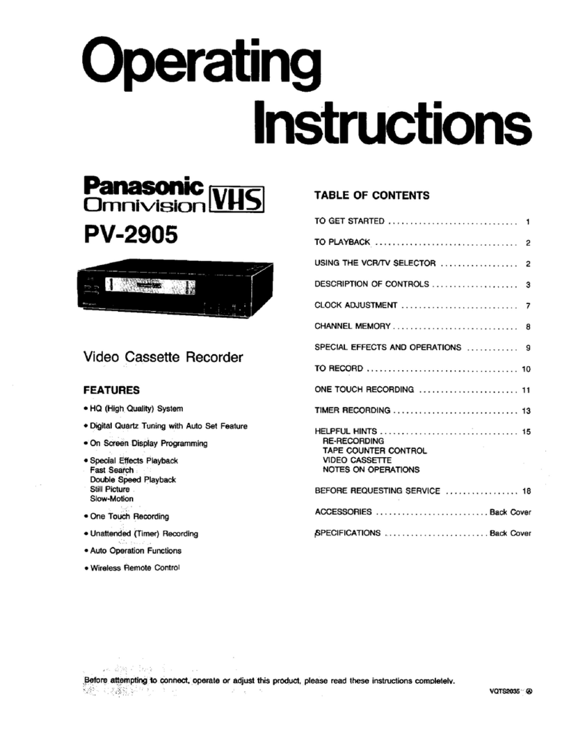
  9. Panasonic Omnivision VHS PV-4905 User manual

Panasonic Omnivision VHS PV-4905 User manual

Other Panasonic VCR System manuals

Panasonic Omnivision PV-7667 User manual

Panasonic

Panasonic Omnivision PV-7667 User manual

Panasonic AG7450 - VCR DOCKABLE User manual

Panasonic

Panasonic AG7450 - VCR DOCKABLE User manual

Panasonic AG-W3P User manual

Panasonic

Panasonic AG-W3P User manual

Panasonic NV-F66A User manual

Panasonic

Panasonic NV-F66A User manual

Panasonic NV-HD600 Series User manual

Panasonic

Panasonic NV-HD600 Series User manual

Panasonic OmniVision PV-QV200 User manual

Panasonic

Panasonic OmniVision PV-QV200 User manual

Panasonic AJ-D230H User manual

Panasonic

Panasonic AJ-D230H User manual

Panasonic NV-HD642EE User manual

Panasonic

Panasonic NV-HD642EE User manual

Panasonic AG-DS850P User manual

Panasonic

Panasonic AG-DS850P User manual

Panasonic Hi-Fi) User manual

Panasonic

Panasonic Hi-Fi) User manual

Panasonic AG-DTL1 User manual

Panasonic

Panasonic AG-DTL1 User manual

Panasonic AG-DV2000P User manual

Panasonic

Panasonic AG-DV2000P User manual

Panasonic AG-DV2000P User manual

Panasonic

Panasonic AG-DV2000P User manual

Panasonic NV-J45 Series User manual

Panasonic

Panasonic NV-J45 Series User manual

Panasonic AJ-D230H User manual

Panasonic

Panasonic AJ-D230H User manual

Panasonic Omnivision PV-8450 User manual

Panasonic

Panasonic Omnivision PV-8450 User manual

Panasonic Omnivision PV-8455S User manual

Panasonic

Panasonic Omnivision PV-8455S User manual

Panasonic AG3200 User manual

Panasonic

Panasonic AG3200 User manual

Panasonic AJ-HD1700PE User manual

Panasonic

Panasonic AJ-HD1700PE User manual

Panasonic AG5700P - SVHS User manual

Panasonic

Panasonic AG5700P - SVHS User manual

Panasonic AJD230HP User manual

Panasonic

Panasonic AJD230HP User manual

Panasonic AGRT600AP - TIME LAPSE RECORDER User manual

Panasonic

Panasonic AGRT600AP - TIME LAPSE RECORDER User manual

Panasonic NV-HS820EE User manual

Panasonic

Panasonic NV-HS820EE User manual

Panasonic OmniVision PV-QV200 User manual

Panasonic

Panasonic OmniVision PV-QV200 User manual

Popular VCR System manuals by other brands

RCA VR678HF user guide

RCA

RCA VR678HF user guide

Zenith VRL4270HF Operating guide & warranty

Zenith

Zenith VRL4270HF Operating guide & warranty

Akai VS-606EA Operator's manual

Akai

Akai VS-606EA Operator's manual

FUNAI 27C-450 Service manual

FUNAI

FUNAI 27C-450 Service manual

Sanyo VHR-M262EV Service manual

Sanyo

Sanyo VHR-M262EV Service manual

Sony SLV-X37 operating instructions

Sony

Sony SLV-X37 operating instructions

JVC SR-VS20U - Dual Format S-vhs/minidv Recorder instructions

JVC

JVC SR-VS20U - Dual Format S-vhs/minidv Recorder instructions

Grundig GV 7400 EURO Service manual

Grundig

Grundig GV 7400 EURO Service manual

Zenith VCM321 Installation and operating guide

Zenith

Zenith VCM321 Installation and operating guide

JVC HR-A43U, HR-A63U instructions

JVC

JVC HR-A43U, HR-A63U instructions

Aiwa VX-S135U operating instructions

Aiwa

Aiwa VX-S135U operating instructions

RCA VR725HF user guide

RCA

RCA VR725HF user guide

JVC 0703-AH-PJ-BJ instruction manual

JVC

JVC 0703-AH-PJ-BJ instruction manual

TruTech ZV450TT8 owner's manual

TruTech

TruTech ZV450TT8 owner's manual

JVC HR-DVS1EK instructions

JVC

JVC HR-DVS1EK instructions

Sensory Science DDV2120 user guide

Sensory Science

Sensory Science DDV2120 user guide

JVC HR-VP78U instructions

JVC

JVC HR-VP78U instructions

RCA VR611HF user guide

RCA

RCA VR611HF user guide

manuals.online logo
manuals.online logoBrands
  • About & Mission
  • Contact us
  • Privacy Policy
  • Terms and Conditions

Copyright 2025 Manuals.Online. All Rights Reserved.

Operating
Instructions
Panasonic
Omnivision [vl-IS]
PV-4905
Video Cassette Recorder
FEATURES
•HQ (High Quality) System
•Digital Quartz Tuning with Auto Set Feature
•On Screen Display Programming
•Special Effects Playback
Fast Search
Double Speed Playback
Field-Still
Field Frame Advance
Double Fine Slow
•One Touch Recording
•Unattended (Timer) Recording
•Synchronized Editing
•Auto Tracking
•Auto Operation Functions
•TVNCR Unified Remote Control
TABLE OF CONTENTS
TO GET STARTED .............................. 1
TO PLAYBACK ................................. 2
USING THE VCR/TV SELECTOR .................. 2
DESCRIPTION OF CONTROLS .................... 3
CLOCK ADJUSTMENT ........................... 7
CHANNEL MEMORY ............................. 8
SPECIAL EFFECTS AND OPERATIONS ............ 9
TO RECORD .................................. 10
ONE TOUCH RECORDING ....................... 11
TIMER RECORDING ............................. 13
HELPFUL HINTS ................................ 16
RE-RECORDING
(USING SYNCHRO EDIT FEATURE)
AUTO PLAY WITH REPEAT FUNCTION
TAPE COUNTER CONTROL
VIDEO CASSE'FrE
NOTES ON OPERATIONS
BEFORE REQUESTING SERVICE ................. 20
SPECIFICATIONS ............................... 22
,rACCESSORIES .......................... Back Cover
r_gfore attempting to connect, operate or adjust this product, please read ' e instructions com_ VQTS1856
IMPORTANTSAFEGUARDSANDPRECAUTIONS
IINTRODUCllON
Careful attention has been given to this Video product to assure aquality standard
devoted to your safety and enjoyment. This qualdy standard, together with your
personal responsi_lity for the safety o_ yourself and others, will contribute to your
enjoyment. This Video product uses electrical energy and requires prober handling
at all times¸
!o,o o. 7
READAND RETAINTHE SAFETY AND OPERATING INSTRUCTIONS
To make full use of the saleguards incorporated in this unit. read and follow this
basic guide, adopled in part from Underwdter's Laboratories Standard 1409,
Second Edition, before operating this Video product
FOLLOW THE INSTRUCTIONS AND BE SURE TO HEED ALL WARNINGS on
unit and in the manual lot easy maintenance, confident operation and _rouble
free service of this Video product
_NSTALLATION
1 OPERATE FROM A POWER SOURCE INDICATED on this Video product, or
in this Manual Your Eioclric Utility Service Company or Video Products Dealer
will be happy to verify the power source in your home
2 THE GROUNDED OR POLARIZED PLUG IS A SAFETY FEATURE
This Video product may be equipped with either a polarized g-wrfe AC kne
plug or a3 wire grounding type plug
The two wire polarize_ plug (having one blade wider than the other( will fit
into the power outlel only one way If it is a three wire grounding type plug
(having a third pin). it will fit into agrounding type outlet
DO NOT DEFEAT THE SAFETY PURPOSE OF THE GROUNDED OR
POLARIZED PLUG by tampering with it
If the plug does not fit tully into the socket, try reversing it tf you should still
be unable to fully insert the plug into the socket, you may find that a proper
outlel is needed to meet today's ElecBical Standards An electrk_ian will replace
your outlet safely
3 POWER SUPPLY CORDS SHOULD BE PROTECTED and routed so that they
are not likely to have anything rest on them, roll over them. Of be subject to
walking traffic or abuse: particularly at plug-ms, Convenience receptacles, or
cord exit points from the unit. Where an extension is needed, use a grounded
Or polarized cord.
HAZARDOUS FRAYED CORDS OR DAMAGED PLUGS SHOULD BE
REPLACED BY A QUALIFIED SERVICE TECHNICIAN
OVERLOADED WALL OUTLETS AND EXTENSION CORDS PRESENT
DANGEROUS RISKS OF FIRE OR ELECTRICAL SHOCK
4 AVOID BLOCKING VENTILATION HOLES
Your video unit has ventilation openings in its tablet Io release heat generated
during operation Blocking these openings can cause heat build-up inside the
unit. causing failures that may result in a fire hazard or heat damage to
cassettes. For protection:
a Never cover the bottom ventilation slots o€ the unit with soft material, or
operate the unit placed on a bed, sofa, rug, or soft accessory
b Avoid bolltgn instaJlations such as a bookcase or rack, unless proper
ventilation is provided
5AVOID EXTREMELY HOT LOCATIONS OR SUDDEN CHANGES IN
TEMPERATURE such as plaeir_ the unit near or over a radiator, in direct
sunbght, closed vehicles, or transporting it suddenly between areas of extreme
temperature variation.
If the unit is suddenly moved from a cold place to awarm place, moisture
may form on the tape and inside the unit.
6. TO AVOID INJURY TO ACHILD, ADULT; OR COSTLY DAMAGE:
aDonotplaceunsecuredequipmentonasiopingsurfaceoranyheavyobjecl
on uoll
(Use the unit in a horizontal position and do not place anything heavy on it)
b. Support for VCR should pe_ededuately firm, level, and strong Replace any
unstable cart, table or support
An appliance and cart combination
should be moved with care. Quick
stops, excessive force, and uneven
surfaces may cause the appliance and
cart combination to overturn
c Carefully follow all operating instructions and use _he manufacturers
recommended accessories when operating this unit or connecting it to any
other equipment
IOUTSIDE ANTENNA, EQUIPMENT, ANO POWERLINE EXPOSURE
1 INSURE SAFE ANTENNA AND CABLE
CONNECTIONS
_,_. "* _,_ If an outside antenna or cable system is
._- _-_ connected io the equipment, be sure the
__,-*_" "_' *"'\_- iantenna or cable system is grounded so
__'_ _ '::_',_, a, to provide some protection against built
._ _, of the Canadmn Electrical Cede, in USA
_."_._ i _'_ Section 810 of the National Eleclr_ca_
;_2,_, Code. ANSI/NFPA NO 70-1984, prowdes
_ '_, _. _ grounding othe mast and supporting
_2_,_E _,_ _, ,,_,, _ structure, grounding of the lead-in wire o
_L.Nr,_pE. : ,"_'_ L._5 a n antenna discharge unl|, size of
_._ _,_c,_ grounding conductors, location of antenna
_e_,_;,_,_ discharge unit, connection to grounding
•,__,,,_,. electrodes and reqolrements for the
Figure 1 "_"_"_ _ o_, grounding electrode See figure 1 for items
a-d below
aUse No 18 AWG (53 mm=) copper, No 8 AWG (84 mm _) aluminum
NO 17 AWG (1 O mm _) copper-cled stee_ or bronze wire, Or larger, as
ground wire.
b Secure_ntennalead-ioandgroundwirestohousewdhstand-offinsulators
spaced from 4 feet (!22 m} to 6 feet (183 m) apart
cMount antenna discharge unit as close as possibio to where lead-in enters
house
d Use jumper w_re not smaller than No. 6 AWG (133 mm z) copper, or the
equivaiont, when aseparate antenna-grounding electrode is used See NEC
Section 810-21 (j} fol installation in USA
2 ELIMINATE ANTENNA PROXIMITY TO HIGH VOLTAGE POWER SOURCES,
OR CHANCE OF ACCIDENTAL CONTACT BY INSTALLER
An outside antenna system should be located where it wi_l never be reached
by power knes. electric _ight or power circuits and where it will never eonIBct
these power sources if it falls Installer shoold use extreme care to avoid
possible fatal contact by touching power lines, circuits or other power sources
when installing an OUtSide antenna
IusB !
AFTERSTOR,NGORWRENOV,NGTREUN,TREFERTOTRE
,NOTA LATIONSECT,ONOFTREBAFEGUARDB
1DO NOT USE THIS VIDEO UNIT NEAR WATER: around b_fthtubs sinks.
laundry, wet basement, swimming poo! or any water source.
USE ACCESSORIES RECOMMENDED ONLY BY THE MANUFACTURER to
avoid risk of fire, shock or other hazards
3UNPLUG ALL EQUIPMENT EXPOSED TO RAIN, MOISTURE, OR STRONG
IMPACT AND GET A QUALIFIED INSPECTION
It your unit has been exposed to rain, water excessive moisture, Or subleoled
to strong impact, unplug it and have il inspected by a service technician before
use
4 UNPLUG UNUSED UNIT, AND ALL EQUIPMENT DURING A STORM
Dudng a lightning storm, when indoors or outdoors, or before leaving unit
unused for ex_eoded periods of time, disconnect all equipment from the power
source, arrfenna and cable system
5 UNPLUG ALL EQUIPMENT BEFORE CLEANING After unit has been
unplugged use a dry, clean, chemically untreated cloth Use no cleaning fluids
aerosols, or forced air that could over-sprayr or soak into the unit, and cause
electrical shock Any substance such as wax, adhesive tape, etc may affect
the cabinet surface Exposure Io greasy, humid, or d_sty areas may affect
internal parts
6. WHEN PLUGGED-IN: KEEP WATER AWAY: NO FINGERS INSIDE NOR ANY
OBJECTS INSIDE: AND NO MAGNETS OR ELECTRIC,_L INTERFERENCE
NEARBY.
aNeveroperaletheuoltdliquidhasbeenspilledintod lmmediatelyunplug
the unit, and have i_ inspected by a service technician Fire and shock
hazards can result from eleeledal shorts caused by liquid contact inside
b Caution the children aboul dropping or pushing objects into the unit Some
parts inside carry h_.zardous voltages and contact can cause electric shock
Objects dropped into electrical equipment can cause fire hazards
c Separate the unil Eom any interference causing appliances Placing the unit
directly above or below your TV set may cause electrlcal interference Keep
all magnets away ftom electronic edu_pment
[SERV,CE ]
1DO NOT ATTEMPT TO SERVICE THIS PRODUCT YOURSELF
If this VialeD product does not operate as described when the deIaiiod
Operating Instructions are followed, do not attempt to open or remove covers
or make any adiustments not described in the manua_ Aftemptiog Io service
this unit yourself may expose you to dangerous voltage or other hazards Refer
all servicing to qualilied se_ice personnel
2CHECK ON REPLACEMENT PARTS REQUIRED Be sure the sew_ce
technician has used replacement parts specified by the manufacturer or having
the same characteristics as the original part Unauthorized Substitutes may
result in tire, electric shock or olhet hazards
3 HAVE TECHNICIAN PERFORM SAFETY CHECK des_rioed in the
manuf_,iurer's servi_e lit et alure, afler any se _'_ce or repairs, to determrne that
Ihe V_deo unit _s in safe operating order
VQTBIg32 A
BASIC GUIDE FOR VCR CONNECTION
CONNECTIONS TO MAKE BEFORE RECORDING
[1] HOMEANTENNASYSTE.
Before you can record TV programs, you must disconnect your existing antenna from your TV (shown in step 1) and re-connect the
antenna to the VCR (shown in step 2). Next, using the RF Coaxial Cable packed with your VCR, connect your VCR to your TV
(shown in step 3) This is all that is necessary if you have a home antenna.
However, if you are connected to a cable system, see sections 2-5 on this sheet. You may also need aconverter/descrambler box
from your cable company to complete your cable hook-up.
STEP 1•ANTENNA FROM
YOUR TV
Your antenna should have one of the cable ends shown in one of the diagrams below,
To avoid confusion, label all terminals and cables before disconnecting anything.
COMBINATION
t- VHF/UHF SYSTEM--
A•VH
FVHF ONLY
g •
--or_
300-75 ohm
Transformer L_.
,not
SEPARATE VHF/UHF
FSYSTEMS COMBINED--
k
r-UHF ONLY
L_.... _ ,
]
UHF/VHF Band
"_"_ _I Mixer
_ _oLr_lnot supplied)
300-75 ohm -_ _
Transformer LL_ "_
_pplied)d __
_ )_
Transformer
(not supplied)
., i | S_
Use only one
m
YOU can con
"IN FROM A
You can als(
Mixer post (n
post (not sul
"IN FROM A
(300 ohm "T
antenna to y,
Baok Panel of ...... S;'_"] [_'_'''''
,,,J,J TV may be ' :
;,F_eone of these L.......... ,• .......... ,
r.......... ,,_ ................ ._..
-:i ][ ]
• .......... d t.......... J t, ..........
There are many types of antenna terminal arrangements on the
back of TV's To the left are some examples which may match
yours
The Part shown right is packed with your VCR.
Contact your Dealer or electronics supply store
for the other parts shown below.
1 pc. RF Coaxial
Cable
Used in step 3
CONNECT YOUR
PYOUR VCR
,nection.
/
/I
/1
/,' t
,,/ i
./ I
I
VIDEO AUOIO
_.,,._.,o..3 0
JODDODOOODODDIODBD9
,ct a round cable (75 ohm) directly onto the
F." POST (75 ohm) on the back of the VCR.
:onnect a round cable onto a UHFNHF Band
supplied) or onto the 300-75 ohm Transformer
ied), before connecting either of these to the
F," post on the back of the VCR. A flat cable
nLead") can also be used to connect your
r VCR in this step.
STEP 3 co..,c..oo,o.o,.
VCR TO YOUR TV r'-'-_------; "_
, 13/Antenna, -_ i
:Pa.*l ',
First look at the back panel of your TV, then find the I
appropriate diagram below and use that method to connect s i J
the VCR to the TV. Use one connection only. .. L-F" ___ -j..
r-COMBINATION VHF/UHF SYS_I'EMF"
A ::......... _"
I_. 'm/uqF
I I ....... !
I (Example)
......
___.,
I UHFNHF Send (Optional Connection/not
Separator supplied)
FVHF ONLY
g •
f
RF Coaxial Cable
or
(supplied)
k
75-300 ohm
Transformer (_ .
(not supplied) I ._--,_ I /i .......... i_--_--';\_
I-SEPARATE VHF/UHF SYSTEMS COMBINED-
CUHFNHF Band S_oarator _-"'_r_"] *
--'.c..,c.,.
L_ ' ,"Transformer (not supplied)
l UHFNHF Band Separator (Optional Connection/not supplied)
FOR UHF-ONLY antenna systems
Even if you plan to play back tapes or view and record UHF
programs, you still need to make ofle of the combination
VHF/UHF connections shown above, because when in
operation, your VCR sends VHF signals to the TV across the
RF Coaxial Cable.
* If your TV has both post and screw-type VHF terminals,
using the 75 ohm post connection is recommended to minimize signal loss.
CONNECTIONS TO MAKE BEFORE RECORDING (CONTINUED)
CABLE CONNECTIONS
[2] ,B,s,cc,B,ECONNECTION ]
WITH A (CABLE TO VCR) CONVERTER/DESCRAMBLER BOX
!: _'rourcab!o, service s;;opiies you with a converter box, you can use the basic connection shown here If your cable system is different,
,efer to the ALTERNATE CABLE CONNECTIONS on the following pages Back of TV
Cable TV IN FROM ANT. OUT TO TV 1 1 ........... -.-"_
Converter Box \ J TV Ante-nn_- -I¢
_\ /ane, i !
CATV (cable) ,j
Input J _ _ ../'_:_ "_.; J _- I 2_ _'_'_: I " ,'"
With this connection you can record and view any channel including scrambled channels• However, channel selection must be made
at !he cab!e compar__y converter box This means that channels cannot be changed using the VCR Remote Control Unattended
recording is limited to one channel at a time, and you cannot view another channel other than the one you are recording•
TO RECORD AND VIEW A SCRAMBLED/UNSCRAMBLED CHANNEL
1 Set the VCR,'TV selector located on the front of VCR to "VCR".
2 Set the TV channel selector to the output channel of the VCR (channel 3 or 4).
3 Set the VCR channel selector to the output channel of the Cable Converter Box (e.g. CH 3).
4 Select the channel to be recorded at the Cable Converter Box.
TO WATCH TV (WITH THE VCR OFF)
I Set the TV channel selector to the output channel of the Cable Converter Box.
2 Select the channel on the cable converter channel selector,
Note to CATV system installer:
IThis reminder Is provided to call the CATV system installer's attention to Article 820-22 of the NEC in USA (and to the Canadian
Electrica! code in Canada) ha provides guidelines for proper grounding and, in par£cular, specifies that the cable ground shall be
!connected to the grounding system of the building, as close to the point of cable entry as practical
[3] {.'T,.N.TEC..'.CONNECT,ON
WITHOUT A CONVERTER/DESCRAMBLER BOX
Use _his connection if your cable system connects directly to your TV without a converler box
IN FROM ANT. TV
CATV _neut
tr,, o,_r, _;_)op you car, t) use your VCR Remote Control to select channels g) program ope or more unscrambled channels
...!l. •'r,_cor_!,q _; :i *.. _oe c:h_lnn_i wh_le recording another
,, !],. _-: me ._;_ _ HANNEI ill: []©WN Kt._y:- ',, s(!lect fhe d[,slr_:t! of,anne!
' ! #_C r,j :-_r %,t_* l _¢ !_tr]_{ji_. d i:_f!l;f,,: ¢¢;t_- _his coflner:{!(_ :
[4] tAuterNAte cABLEcOnnEcT,ON
WITH A (VCR TO TV) CONVERTERIDESCRAMBLER BOX
If your cable system uses a converter box, you may use this connection instead of the basic cable connection shown on the prewous
page. Consult your local cable company first, if necessary.
IN FROM ANT. OUT TO TV
CATV Input
Cable TV
Converter Box
With this connection you can 1) program unattended recording of more than one unscrambled channel 2) view one channel while
recording another
NOTE: • Use the VCR CHANNEL UP!DOWN Keys to select a channel to be recorded• You cannot record scrambled channels with this connection.
To Record One_Channe! while Vjwing Another
1. Select the channel to be recorded with the VCR CHANNEL UP/DOWN Keys
2. On the VCR set the VCR/TV selector to "TV"
3. Set the channel selector on the TV to the output channel of the Converter Box
4. Select the channel to be viewed on the Converter Box.
To Play Back a Tape
1. Set the VCR/TV selector to "VCR".
2 Set the TV channel selector to the output channel of the Converter Box
3. Set the Converter Box channel selector to the VCR output channel (channel 3 or 4).
[5] [ALTERNATECABLECONNECT,ON[]
WITH TWO CONVERTER/DESCRAMBLER BOXES
If you want to record and view combinations of scrambled and unscrambled channels you will need additional equipment A typical
connection using two converter boxes, an AJB Switch, and a 2-way Splitter is shown here.
2-Way
Splitter OUT 1
CATV Input
Cable "IV
Converter
Box #1
IN FROM ANT OUT TO TV
/
. / ,,
A/B Switch
Settings for Recording and TV Viewing
1. Set the VCR channel selector to the output channel of Converter #1.
2. Select the channel to be recorded on Converter #1.
To view the channel being recorded:
• Set VCR/'rv selector to "VCR".
•Set the A/B Switch to position A.
• Set the TV channel selector to the VCR output channel (channel 3 or 4).
NOTE: •These settings are also used to view playback of a tape.
•Converter Boxes, Splitters and Cables shown are not supplied.
To view a different channel:
•Set the A/B Switch to position B.
•Set the TV channel selector to the output channel of Converter #2.
•Select the channel to be viewed on converler #2.
[6] Tv Auo,oN,oEOCO..ECT,O.S
If your TV has AUDIO IN and VIDEO IN terminals, you can connect the AUDIO OUT and VIDEO OUT connectors on your VCR to
these terminals on your TV to receive a higher quality picture and sound.
VHF Antenna UHF Antenna
UHF/VHF Band VHF IN _VIDEO IN
Serrate, tV
Y _ UHF IN _ \
OUT TO " AUDIO iN
TV Terminal AUDIO OUT
(not supplied) S;_
IN FROM ANT.
Terminal
VIDEO OUT
NOTE:
• To use your TV as a VCR monitor, set the VIDEOFrV selector on the TV (Monitor/Receiver) to "VIDEO".
// J
(two lines for '
It you connect the VCR to a component stereo audio system, you can view the VCR picture on TV with sound from the audio systel
AUDIO OUT
OUTPUTS
two lines for )AMPLIFIER
Stereo/Hi-Fi
To ACCESSORIES INCLUDED IN THE CARTON"
GET STARTED ARE SHOWN ON THE BACK COVER
II
i_! _ODUCT!ON
We are pleased to introduce you to one of the most sophisticated entertainment products available today. Shown below are
the two steps necessary for playback. To watch TV and record, additional connections are needed; see the separate Connections
Guide accompanying this manual. Keep this manual near your VCR for quick reference.
ONE TIME SET-UP STEPS
Setting the clock is not actually necessary for playback, but is necessary for all types of timer recording. Please refer to page 7 to
set the clock.
VCR TO TV CONNECTION
A connect to a TV that has a VHF 75 ohm Post
VHF OUT
(OUT TO __
Back of TV (example only)
F_ !I
RF Coaxial Cable (supplied)
BConnect to aTV that has VHF 300 ohm Twin screws "IV
VHF OUT_
(OUT TO TV)_
(A UHFNHF Band Separator can also _(_ r_
be added. See the separate "Basic • -- I
Guide For VCR Connections".) RF Coaxial cable (supplied)
r- l ,I
.SELECT VCR CHANNEL (CHANNEL 3 OR 4)
Your VCR translates video and audio signals from the VCR into standard signals that your TV can receive on CH3 or CH4.
This signal will be broadcast to the TV through the RE Coaxial Cable.
You decide which TV channel to use by selecting either channel 3 or 4 with the CHANNEL 3/4 Switch on the back of the
VCR. The CHANNEL 3/4 Switch should be set to the channel that is not normally occupied by a TV broadcast in your area,
to avoid local interference.
TO WATCH CHANNEL SELECTED AT THE VCR
First connect the VCR and TV power plugs
to AC outlets. Then tune your TV to the
VCR CHANNEL, the same channel that you
selected with the CHANNEL 3/4 Switch.
Select channels using the CHANNEL
UP/DOWN Keys or the Remote Control
NUMERIC Keys (see page 3).
VCR CHANNEL
_r_ _ 3/4 Switch
I
[] _ Back of VCR CH4, CH3 []
WARNING: TO PREVENT FIRE OR SHOCK HAZARD, DO NOT EXPOSE THIS EQUIPMENT TO RAIN OR MOISTURE.
This video recorder, equipped with the HQ System, is compatible with existing VHS equipment.
Only use those tapes with the _mark. It is recommended that only cassette tapes that have been tested and
inspected for use in 2, 4, 6, and 8 hour VCR machines be used.
CAUTI'_ _O _IE_CE _: _rsK Or E_[CTFIIC S_K
OO NO1 RF'AOVE COVER qC_ BACKj
NO L_;_H SI_RV_C[ASI • PAroS _NSJO¢
This symbol warns the user that uninsulated voltage within the unit
may have sufficient magnitude to cause electric shock. Therefore, it is
dangerous to make any kind of contact with any inside part of this unit.
This symbol alerts the user that important literature concerning the
operation and maintenance of this unit has been included. Therefore,
it should be read carefully in order to avoid any problems.
To F LAV ACK 2
Be sure the PREPARATIONS on page 1 have been completed before proceeding to step 1below.
AT THE TV
"rum the "IV ON and
select its VCR
channel.
The TV's VCR Channel is
either channel 3 or 4.
AT THE VCR
Insert acassette.
The Power will come ON
automatically.
If the Record Tab (page 18) is
removed, playback will start
automatically. (In this case
skip step 3.)
if acassette is afteady in the
VCR, just press the POWER
Button ON.
START PLAYBACK
Press the PLAY
Button.
The VCR Indicator will light.
This automatically sets the
VCR mode (see below).
For Special Effects see
page 9.
STOP PLAYBACK
Press the STOP
Button.
• Press the EJECT Button to
remove the cassette.
PLAY
BuTroN
POWER ON; STOP/EJECT STOP
SELECT THE BUTTON
VCR CHANNEL BuTroN
USING THE °SELECTOR
GD QD CD
Q27 CD CD
J J J J
CJ_ _ ZJ
VCRKV
SELECTOR
NUMERIC
KEYS
CHANNEL
UP/DOWN
KEYS
After you have a cable system or antenna connected to your VCR and the "TO GET STARTED" connections on page 1are
complete, you can begin to watch TV broadcast channels using your VCR or TV tuner.
ANTENNA (or CABLE) Remote Control VCR/'I'V Selector
L
VCR Indicator "VCR"
TO SELECT CHANNELS AT THE VCR FOR VIEWING OR RECORDING
It is necessary to place the VCR in the "VCR" mode. Be sure that the TV is tuned to the same channel which was selected
for the VCR channel (CH3 or 4) above,
1) WHEN YOU TURN ON YOUR VCR
The "VCR" mode is automatically selected, just turn the TV power ON and select the VCR CHANNEL,
2) WHEN THE VCR POWER IS ALREADY ON
The VCR Indicator should show on the front panel,
If the VCR Indicator is not showing, select the "VCR" mode by pressing the VCR/TV SELECTOR Button once,
Select channels using the VCR REMOTE CONTROL CHANNEL UP/DOWN Keys or the NUMERIC Keys.
TO SELECT CHANNELS AT THE TV FOR VIEWING
In "TV" mode no "VCR" indicator shows on the front panel.
I) WHEN THE VCR IS TURNED OFF
The "TV" mode is automatically selected, just turn the TV power ON
2) WHEN THE VCR POWER IS ALREADY ON
If the VCR Indicator is showing and the TV is already ON select the "TV" mode by pressing the VCR/TV SELECTOR
Button once. The VCR Indicator should NOT show on the front panel
Select channels using the TV channel controls.
DESCRIPTION OF CONTROLS
CASSETTE COMPARTMENT
VCR/TV SELECTOR BUTTON-- !/f
WIRELESS REMOTE _/, t _ _ _k_,_._,
POWE.OU.ON l! /,/ ,
CHANNEL-- t_ -- ( "_
/\
REWlND/(_ SEARCH
BUTTON
FAST FORWARD/
SEARCH _BUTTON
-- MULTI FUNCTION
DISPLAY (Page 5)
-- RECORD BUTTON
PLAY_2 BUTTON
STOP/EJECT BUTTON
POWER BU'I-FON
-TO turn the VCR on and off.
-To set the VCR for unattended
recordings after timer programming
have been completed.
PLAY/X2 BUTTON
To play back a tape.
In SP or SLP playback, tap this button
once more for a rapid search at twice
normal speed.
STOP/EJECT BUTTON
To stopthe tape. To removeacassette
in the stop mode.
ImI_I£LI_ ;Eli _]l;l:ll] :1:U,[o;III :ll(s] _Ii :Ill II
Various VCR function controls are conveniently available with your Wireless Remote Control.
NOTE: The Unified Remote Control controls TV functions of certain Panasonic TV models only.
TV CONTROLS
CHANNEL UP/DOWN
TV POWER BI
SLEEP TIMER BUTTON
MUTE BUTTON
VOLUME
CLEAR/RESET
CLOCWCOUNTER
MEMORY BUTTON
RECALL BUTTON
STANDBY BUTTON
(OTR) BLFI-rON
REWIND/(_
SLOW-MOTION BUTTONS
REPEAT BUTTON
FRAME ADVANCE BUTTON
VCR POWER BUTTON
EJECT BUTTON
VCR/TVSELECTOR BUTTON
5, 6, 7, 8, and 9)
L UP/DOWN KEYS
BUTTON
SPEED SELECTOR
BUTTON (SP/LP/SLP)
BUTTON
BUTTON
PAUSE/STILL BUTTON
FAST FORWARD/SEARCH
BUTTON
DOUBLE SPEED (X2) PLAY
BUTTON
TRACKING CONTROL
BUTTON
CHANNEL MEMORY BUTTON