TVP-2914
9
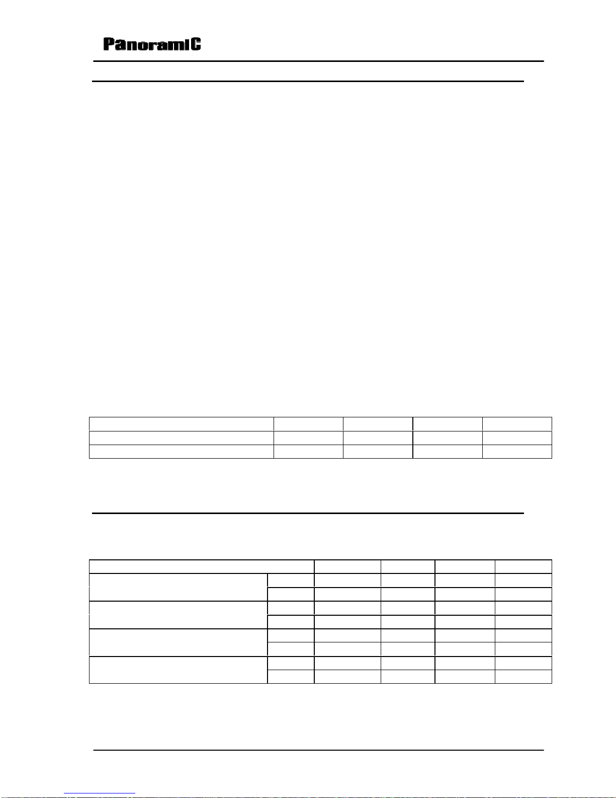
e) Repeat all below procedures, connecting now the television under test to a
110Vac/60 Hz line.
Condition Minimum Nominal Maximum Unit
117VAC“PP” - - 125,00 W
117VACStand-By - - 3,00 W
234VAC“PP” - - 125,00 W
234VACStand-By - - 3,00 W
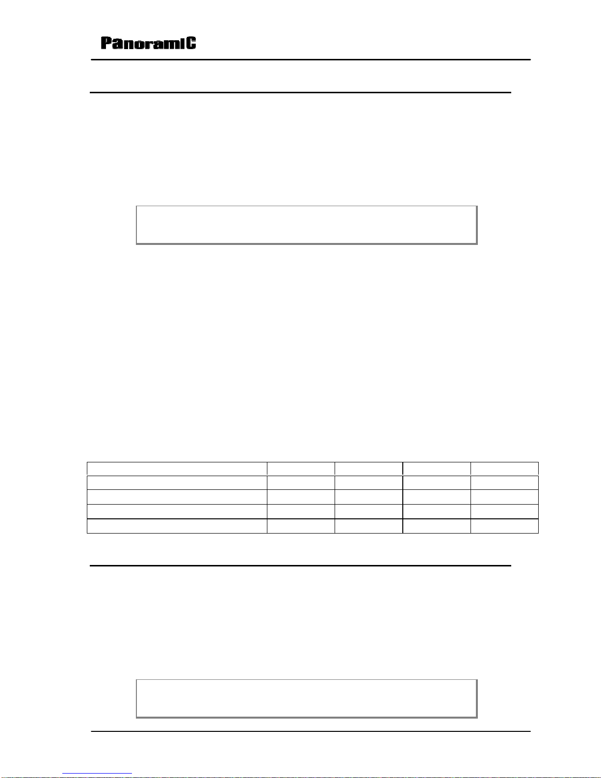
2.2.2 Main Power Supply
a) Connect the TV set under test to 110Vac/60Hz line.
b)Turn on the TV and apply a 60dBµV signal (frequency and channel defined
by factory) 88% modulated with white pattern and audio signal with 400Hz
frequency modulated in FM with ±25kHz of deviation.
c) Adjust the TV to a “PP” condition.
d)Utilizing a electronic DC voltmeter ( over 10 M input impedance), read the
next point in the power supply.
Condition Test Point Minimum Nominal Maximum Unit
“PP” 117VAC +B (Cathoe of D807) 130,50 132,50 134,50 VDC
“PP” 117VAC Áudio (Cathode of D808) 20,00 22,00 24,00 VDC
“PP” 117VAC Tuner (Cathode of DZ101) 30,00 33,00 36,00 VDC
“PP” 117VAC +5V (Emitter of Q101) 4,50 5,00 5,50 VDC
“PP” 117VAC +3V3 (Emitter of Q804) 3,00 3,30 3,60 VDC
“PP” 117VAC +8V6 Áudio (Emitter of
Q805) 8,00 8,60 9,00 VDC
“PP” 117VAC +8V Video (Cathode of
DZ807) 7,60 8,00 8,60 VDC
2.2.3 Main Power Supply Regulation with fluctuation of the line
Repeat the procedure of the item 1 when the television is connected to the
electric net with 100VAC/60Hz and also 220VAC/60Hz.
Condition Test Point Minimum Nominal Maximum Unit
“PP” 240VAC +B (Cathode of D807) 130,50 132,50 134,50 VDC
“PP” 240VAC Áudio (Cathode of D808) 20,00 22,00 24,00 VDC
“PP” 240VAC Tuner (Cathode of DZ101) 30,00 33,00 36,00 VDC
“PP” 240VAC +5V (Emitter of Q101) 4,50 5,00 5,50 VDC
“PP” 240VAC +3V3 (Emitter of Q804) 3,00 3,30 3,60 VDC
“PP” 240VAC +8V6 Áudio (Emitter of
Q805) 8,00 8,60 9,00 VDC
“PP” 240VAC +8V Vídeo (Cathode of
DZ807) 7,60 8,00 8,60 VDC