1
Section 1 Amplifier System Description
1.1Introduction
This manual contains information and procedures for installation, operation, and maintenance of Paradigm
Wireless Systems MAF800-100S multi-carrier cellular amplifier. This manual is organized into the
following sections:
Section 1. Amplifier System Description
Section 2. Specifications
Section 3. Principals of Operation
Section4. Operating Instructions
Section5. Installation
Section 6. Maintenance
Section 7. Troubleshooting
1.2 General Description
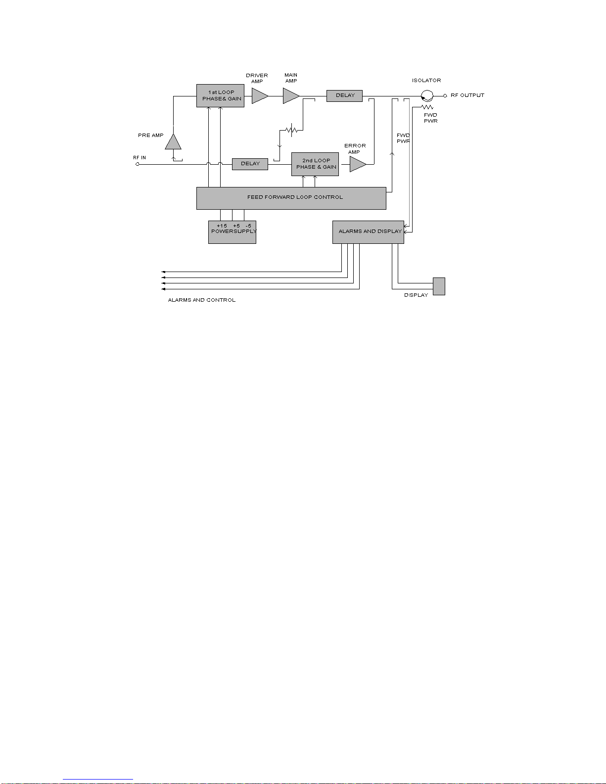
The MAF800-100S is a linear, feed forward power amplifier that operates in the 25 MHz frequency range
from 869 MHz to 894 MHz. The average output power of the amplifier is 100 Watts average AMPS,
CDMA, CDMA 2000, 1xEV-DO, GSM, TDMA, and EDGE. The amplifier is designed to operate ina
maximum of two continuous modulations or a total instantaneous bandwidthof 25 MHz. The amplifier can
simultaneously transmit multiple frequencies, with a better than –13 dBm third order intermodulation
distortion. The amplifier is designed and suited for use in CDMA, TDMA, EDGE and GSM radio base
stations. A sub-rack is employed to combine the outputs of up to (4) MAF800-100S amplifiers. Each plug-
in module operates in parallel to produce a high peak output power and fail safe redundancy for trouble free
operation with minimum maintenance. A multi-color LED detects when a fault condition has occurred
within the amplifier. The LED will turn fromGREEN to RED duringanamplifier fault condition.
Eachamplifier has a status connector thatallows the host system to monitor the amplifier module
performance. Monitoring of the amplifiers is done through the D-subminiature connector on the back of the
MAF800-100S amplifiers. The front panel of the MAF800-100S amplifier has an ON/OFF circuit breaker.
Primary +27 Vdc power for the MAF 800-100S amplifiers is provided through the sub-rack assembly.
The sub-rack contains the fan assembly for cooling each amplifier. Cooling fans are used to pull air through
the heat sinks. Air movement across the heat sinks dissipates the heat generated by the amplifiers. Constant
airflow ensures the amplifiers performance to specifications.
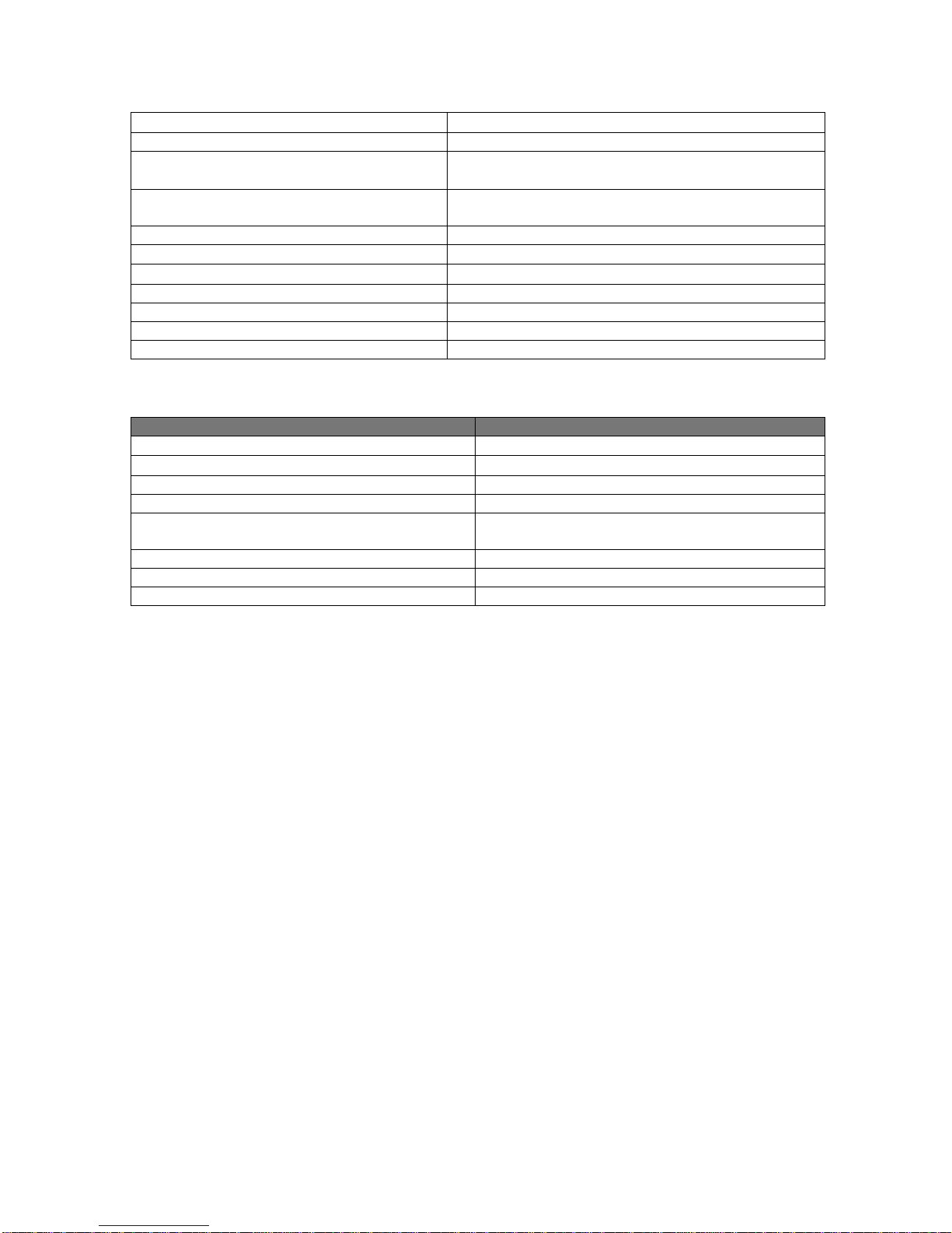
Section 2 MAF800-100S Electrical Specification
Parameter Specification
Frequency 869-894 MHz
RF Gain 58 dB
Gain Variation over Temperature 0.3 dB
Gain Flatness 0.5 dB
Intermodulation Distortion ≤-13 dBm