1
FrameSaverrDSL 9783 Router
Installation Instructions
Document Number 9783-A2-GN11-00
December 2000
Contents
FrameSaver DSL 9783 Router Overview 1. . . . . . . . . . . . . . . . . . . . . . . . . . . . .
Wiring and Cables You May Need 6. . . . . . . . . . . . . . . . . . . . . . . . . . . . . . . . . . .
Installing the FrameSaver DSL 9783 Router 7. . . . . . . . . . . . . . . . . . . . . . . . . .
Status LEDs 10. . . . . . . . . . . . . . . . . . . . . . . . . . . . . . . . . . . . . . . . . . . . . . . . . . . . . .
Troubleshooting 10. . . . . . . . . . . . . . . . . . . . . . . . . . . . . . . . . . . . . . . . . . . . . . . . . . .
Finalizing the Router Configuration Setup 12. . . . . . . . . . . . . . . . . . . . . . . . . . . .
Verifying that Self-Test Passed 14. . . . . . . . . . . . . . . . . . . . . . . . . . . . . . . . . . . . . .
Using the FrameSaver Easy Install Screen 15. . . . . . . . . . . . . . . . . . . . . . . . . . .
Completing Setup From the NOC 16. . . . . . . . . . . . . . . . . . . . . . . . . . . . . . . . . . . .
Provisioning Data Circuits in OpenLane 19. . . . . . . . . . . . . . . . . . . . . . . . . . . . . .
Provisioning the Router Interface 19. . . . . . . . . . . . . . . . . . . . . . . . . . . . . . . . . . . .
Technical Specifications for DSL 9783 Router 23. . . . . . . . . . . . . . . . . . . . . . . . .
Important Safety Instructions 24. . . . . . . . . . . . . . . . . . . . . . . . . . . . . . . . . . . . . . . .
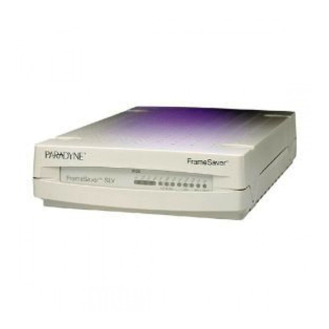
FrameSaver DSL 9783 Router Overview
The FrameSaverrDSL (Digital Subscriber Line) 9783 Router is a component in the
FrameSaver system. This system allows you to perform end-to-end service level
management across a hybrid FrameSaver DSL/ATM/Frame Relay network. QoS
(Quality of Service) capabilities of ATM (Asynchronous Transfer Mode) transport
protocol assures quality of service across the network. Service providers can isolate
and correct problems remotely from their NOC (Network Operations Center).
The FrameSaver DSL 9783 Router has an SDSL front end and is a manageable frame
relay aware endpoint. The router operates as a bridge or an IP router connecting a DSL
link to an Ethernet network.
The FrameSaver DSL 9783 Router is available as a:
HBasic Feature Set 1
HAdvanced SLV (Service Level Verification) Feature Set 2
