Paragon Fires FOCUS HE SLIMLINE User manual

FOCUS HE SLIMLINE
OWNER'S
MANUAL
Please read these instructions carefully before you start
using the appliance
Keep this booklet handy for future reference
This appliance is
for use in Great Britain or
IRELAND only
This appliance is
for use in Great Britain or
IRELAND only
A QUALITY PRODUCT FROM PARAGON FIRES

LT5315 (iss 5) 10/10
2
FOCUS HE SLIMLINE Instructions
CONTENTS
PAGE
USERS INSTRUCTIONS
SECTION ONE Introduction 3
SECTION TWO Operating Appliance 4
SECTION THREE Fuel Bed Cleaning and Layout 5
SECTION FOUR Cleaning 7
SECTION FIVE General Points 9
INSTALLATION INSTRUCTIONS
SECTION SIX Appliance Data 9
SECTION SEVEN Regulations and Warnings 10
SECTION EIGHT Siting the Appliance 12
SECTION NINE To Install Appliance 14
SECTION TEN Checking Fire Operation 16
SECTION ELEVEN Maintenance 18

LT5315 (iss 5) 10/10
3
FOCUS HE SLIMLINE Users Instructions
SECTION ONE Important Information
Consumer Protection Information
As manufacturers and suppliers of heating products, we take every care, as far as is reasonably
practicable, that these products are so designed and constructed as to meet the general safety
requirement when properly used and installed. To this end, our products are thoroughly tested and
examined before despatch.
IMPORTANT NOTICE: Any alteration that is not approved by the appliance manufacturer could
invalidate the approval of the appliance, operation of the warranty and could affect your statutory
rights.
Health and Safety Notice
Important
This appliance could contain some of the materials, indicated below, that could be interpreted as
being injurious to health and safety. It is the users / installers responsibility to ensure that the
necessary personal protective clothing is worn when handling these materials, see below for
information.
Artificial Fuels, Mineral Wool, Insulation Material, Refractory/Ceramic Fibres, Glass Yarn - may
be harmful if inhaled, may be irritating to skin, eyes, nose and throat.
When handling avoid inhaling and contact with skin or eyes. Use disposable gloves, facemasks and
eye protection. After handling wash hands and other exposed parts. If a vacuum is used for cleaning
the coals or cleaning after servicing / installation it is recommended that it be of the type fitted with a
HEPA filter.
Disposal of refractory/ceramic materials. To keep dust to a minimum these materials should be
securely wrapped in polythene and be clearly labelled „RCF waste‟. These materials are not classified
as „hazardous waste' and should be disposed of at a site licensed for the disposal of industrial waste.
The FOCUS HE SLIMLINE is a decorative fuel effect appliance with a radiant heat conserver box
and glass panel for improved efficiency.
The FOCUS HE SLIMLINE incorporates a single gas control, which selects ignition pilot, and
variable settings between Low and High.
This appliance is intended for decorative purposes.
The FOCUS HE SLIMLINE appliance is designed and tested to the requirements of the EN 509.
The appliance is for use on Natural Gas only.
The chimney or flue (unless new or previously used with a gas appliance) must be swept before
installation if it has been used for solid fuel.
WARNING
The glass front of this fire acts as a dress guard, conforming to BS 1945 (1997) however; a fireguard
conforming to BS6539 (1997) must be used to protect young children, the elderly or infirm.
Clothing or other combustible materials must not obstruct the slots at the top of the fire or the base of
the appliance.
SOFT FURNISHINGS
Care must be taken to prevent any damage being caused to surrounding soft furnishing or
decoration; e.g. many embossed vinyl wall coverings may become discoloured if placed too close to
the appliance. Combustible material i.e. wall panelling or wallpaper must be removed from behind the
fire and fire trim.

LT5315 (iss 5) 10/10
4
FOCUS HE SLIMLINE Users Instructions
SECTION ONE Important Information Continued
INTRODUCTION
The FOCUS HE SLIMLINE incorporates a single gas control, which selects ignition pilot, and main
burner low and high settings.
The appliance incorporates a safety device in the form of an Oxygen Depletion System, which
constantly monitors the oxygen in the room and will cause the fire to switch off if the oxygen level
reduces, for instance due to insufficient ventilation or a blocked flue.
If this regularly occurs do not attempt to relight the appliance until a qualified engineer has checked it,
the problem may not be due to lack of air or a defective flue.
A fire front (fret) must be used with this appliance.
In GB, the appliance must be installed by a competent person i.e. CORGI-registered, in accordance
with the GAS SAFETY (INSTALLATION AND USE) REGULATIONS, The Building Regulations (or
The Building Regulations (Scotland) or The Building Regulations (Northern Ireland)) and The Current
I.E.E. Wiring Regulations, if appropriate.
In IE, the appliance must be installed by a competent person and installed in accordance with the
current edition of I.S.813 Domestic Gas Installation, the current Building Regulations and the current
ETCI rules for electrical installation, if appropriate.
The pilot can be left on or the pilot can be extinguished and relit each time the fire is used.
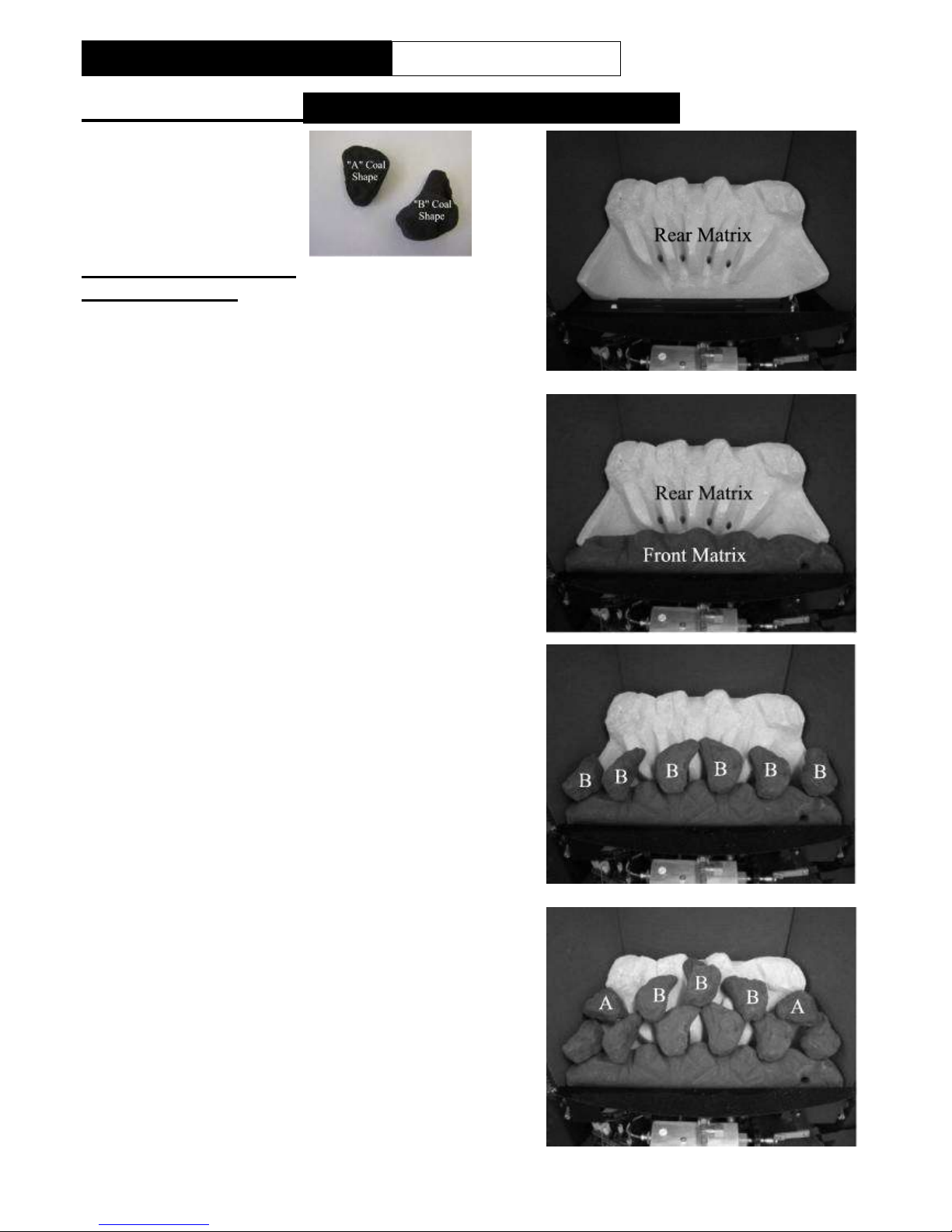
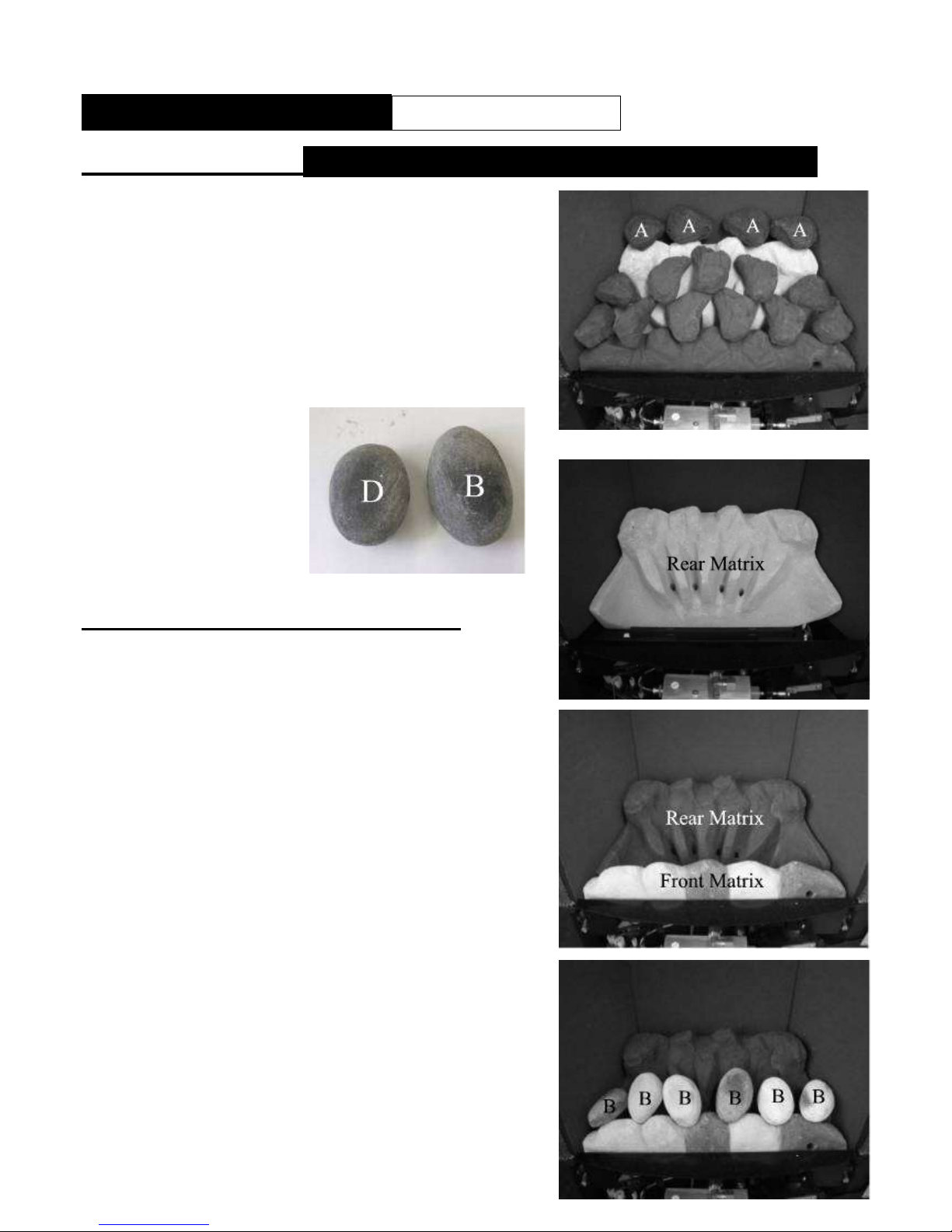
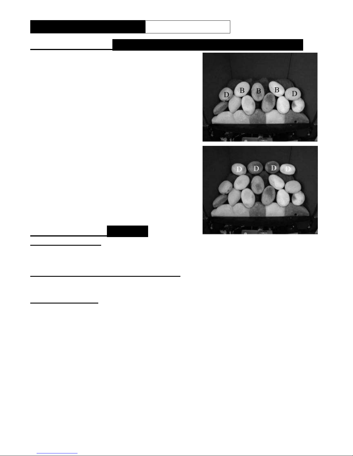
During the normal operation of the fire some black staining may appear on some parts of the fuel
bed. This is quite normal and adds to the appearance of the appliance. However, if excessive black
staining does occur it may be due to the fuel bed being incorrectly laid. This should be checked prior
to contacting a service engineer.
SECTION TWO Operation
Do not use the fire with the glass safety screen removed, or if the glass is cracked.
Do not use the fire with the canopy removed.
The pilot can be left on or the pilot can be extinguished and relit each time the fire is used.
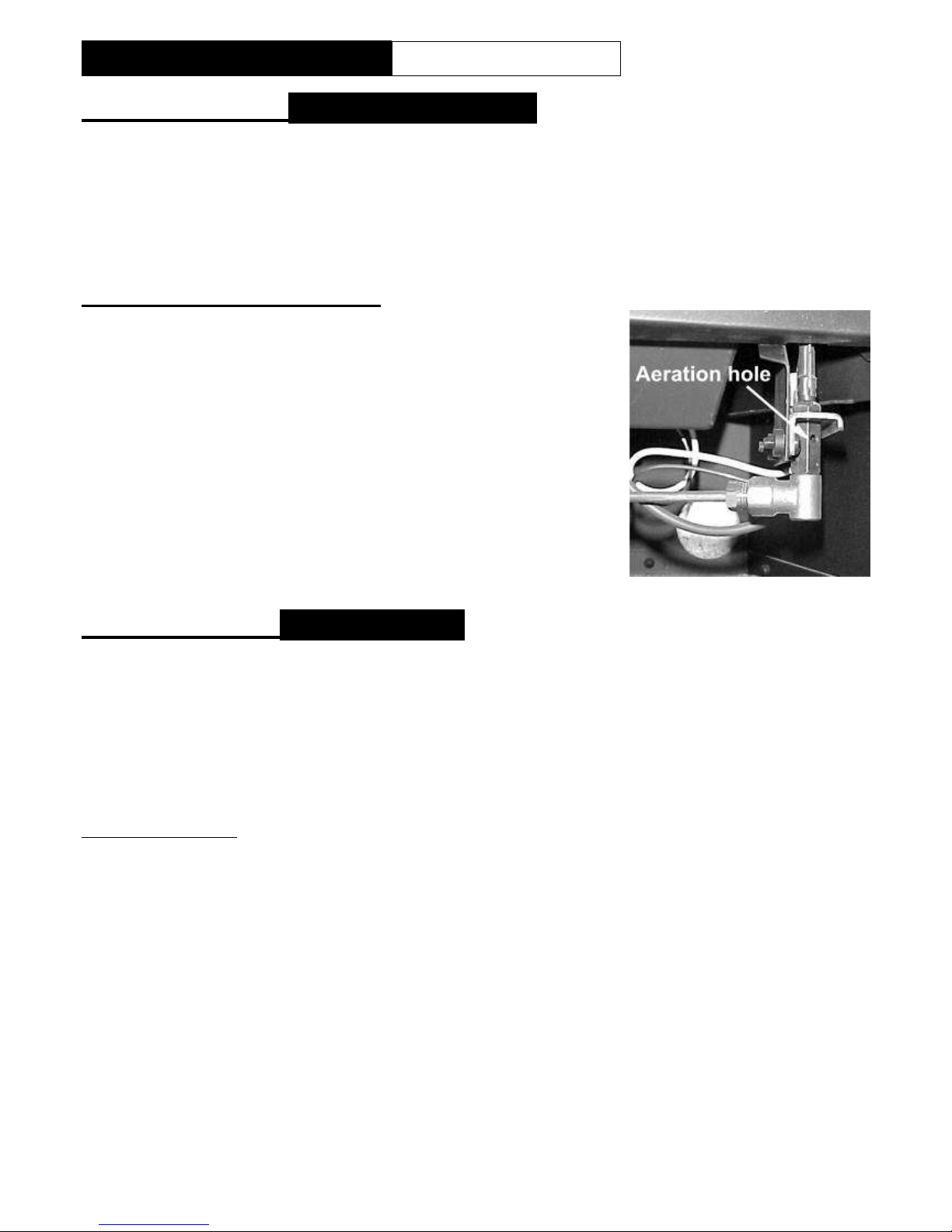
The appliance Control Knob is positioned behind the fret.
The full lighting procedure is as follows: -
a. Push knob in as far as possible on gas control.
b. Turn knob anti-clockwise until a click is heard. The knob will stop at the position marked ' '
and a spark should be seen at the tip of the ignition probe. At the same time the pilot flame
should light. KEEP THE KNOB PRESSED IN FOR 20 SECONDS. Should the pilot fail to
light, turn the control knob clockwise to the ' ' position, wait 3 minutes and repeat the
procedure.
c. After lighting the pilot flame the control knob should be allowed to spring out slightly. This will
allow you to turn the knob further anti-clockwise to the position marked ' '. The pilot flame
should then ignite the main fire.
d. It is possible to adjust the height of the flames by turning the control knob between the
positions marked ' ' and ' '. Note that the knob 'latches' in position at either end of this
movement and must be pushed in slightly before it can be turned.
e. To turn the fire off, depress the knob slightly and turn it to the ' ' position.
f. To completely extinguish the fire, depress the knob slightly and turn to ' ' the position.
Note: -If the ignition fails the pilot can be lit with a taper or a match held at the pilot head.

LT5315 (iss 5) 10/10
5
FOCUS HE SLIMLINE Users Instructions
SECTION THREE Fuel Bed Cleaning and Layout
Warning: - Before you clean any part of the appliance ensures that the appliance is turned off and
cold.
Important: - Refer to the ‘Health & Safety Notice located on page 3 of this booklet before
cleaning or replacing any refractory material.
The fuel bed components are delicate and they should be handled with great care.
The loose parts and moulded shapes may be removed for cleaning. They can be brushed very gently
with a soft brush to remove dust or any deposits.
A vacuum cleaner may only be used after the loose components and moulded shapes have been
removed.
CARE SHOULD BE TAKEN TO AVOID CONTACT WITH THE REFRACTORY LINING THIS IS A DELICATE SURFACE
AND SHOULD NOT BE WIPED OR RUBBED.
REMOVING GLASS PANEL
Remove the trim, which is held in position with magnets.
Remove the fret and ash pan cover.
Lift of the canopy and remove.
Remove the glass fixing clamp secure with three securing nuts and lift it out of the retaining
brackets. Take care to support the glass panel when removing the fixing clamp. The glass should
be place in a safe place to prevent damage.
Once the fuel bed has been laid reassemble in reverse order.

LT5315 (iss 5) 10/10
6
FOCUS HE SLIMLINE Users Instructions
SECTION THREE Fuel Bed Cleaning and Layout
6 OFF “A” Coal Shapes
9 OFF “B” Coal Shapes
FUEL BED LAYOUT
(COAL OPTION)
Ensure the BASE MATRIX is in position as shown
located against the rear edge of the burner outlet.
Locate the Front Matrix as shown.
Locate the first row of coals within the location points
in the front matrix.
Lay a second layer of coals as shown.

LT5315 (iss 5) 10/10
7
FOCUS HE SLIMLINE Users Instructions
SECTION THREE Fuel Bed Cleaning and Layout Continued
Lay the third layer of coal as shown.
Refit glass panel, heat shield, canopy, trim and
fret.
6 OFF “A” Pebble Shapes
9 OFF “B” Pebble Shapes
FUEL BED LAYOUT (PEBBLE OPTION)
Ensure the REAR MATRIX is in position as shown
located against the rear edge of the burner outlet.
Locate the Front Matrix as shown.
Locate the first row of Pebbles within the location points
in the front matrix.

LT5315 (iss 5) 10/10
8
FOCUS HE SLIMLINE Users Instructions
SECTION THREE Fuel Bed Cleaning and Layout Continued
Lay a second layer of Pebbles as shown.
Lay the third layer of coal as shown.
Note: The appliance MUST no be used if the
canopy or glass panel is missing or damaged.
SECTION FOUR Cleaning
CLEANING: BRASS
The brass fret and brass effect fire surround trim may be cleaned with a clean damp cloth.
N.B The trim and fire front should be removed for cleaning. (The trim is held in place by magnetic
strips).
CLEANING: BLACK PAINTED SURFACES
These surfaces should be dusted regularly and any marks removed with a soft cloth.
Abrasive or chemical cleaner should never be used for cleaning these surfaces.
GLASS CLEANING
Note: - The glass may discolour quickly when first installed, and it should be cleaned. This is
due to the burning off process of the refractory shapes.
From time to time it will be necessary to clean the glass panel. We recommend you use a Ceramic
hob cleaner these are available for all leading supermarkets: - i.e. ASDA, TESCO, SAINSBURY’S
Etc.
Brands of hob cleaning we have tested and found suitable are - HOB BRITE & VITRO CLEN.
Ensure that the appliance is cold before cleaning the glass.
To remove glass panel for cleaning:
Remove trim, which is held in position with magnets.
Remove the fret and ash pan cover.
Lift of the canopy and remove.
Remove the glass fixing clamp secure with three nuts and lift it out of the retaining brackets. Take
care to support the glass panel when removing the fixing clamp.
Lay the glass panel down on a flat working surface on top of an old opened newspaper with the
side to be cleaned uppermost.
Follow the instructions on the Hob Cleaner Bottle.

LT5315 (iss 5) 10/10
9
FOCUS HE SLIMLINE Users Instructions
SECTION FOUR Cleaning Continued
On stubborn stains (where the appliance as been used for a long period without glass panel being
cleaned), use a new Brillo Pad well wetted with the Hob cleaner applied directly to it.
Ensure all the residues of the cleaner are removed with a damp cloth and the glass panel is
completely dry before fitting to the appliance.
Check that the coals are correctly placed before reassembling in reverse order.
Note: The appliance MUST no be used if the canopy or glass panel is missing or damaged.
CLEANING: PILOT ASSEMBLY
Pilot Cleaning (Before cleaning ensure that the appliance is turned
off and cold)
In some instances you may experience ignition problems even when
the appliance is new. This may be due to the aeration hole in the
pilot body (see photograph) being partial blocked with dust, pet hairs
or other foreign matter. The source of this debris could be such
things as carpet fibres, decorating or pet etc.
To clean the pilot, remove the fire front and ash pan. The pilot is
located on the right hand side of the appliance, any debris in or
around the aeration hole should be remove using the nozzle of a
vacuum cleaner. It is advisable not to blow the debris into the hole
as this may cause more of a restriction and not rectify the problem.
Note: - Take care when cleaning in this area so as not to
damage the pilot assembly.
SECTION FIVE General Points
Like all appliances incorporating an aerated burner a low frequency noise may be heard.
It is advised that the FOCUS HE SLIMLINE fire be serviced annually by a competent person. The
fire is more likely to provide trouble-free operation. The actions given below should be carried out
during that service.
Dulling and slight discoloration inside the firebox will occur adding to the realism of the appliance, this
is quite normal.
It is important that: -
The chimney or flue is checked annually to ensure clearance of combustion products.
The fire front must be positioned in front of the fire whilst it is burning
Any debris from the chimney or flue should be removed. The fire should be allowed to cool before
it is removed.
The fire must not be used if the glass panel is not fitted or damaged - this includes the seal.
The fire must not be used if the canopy is not fitted.
The data badge is located behind the fret on the right hand side of the appliance.
The only user removable parts are: -
Fret
Refractory Fire bed Components
Canopy.
Trim.
Glass panel.

LT5315 (iss 5) 10/10
10
FOCUS HE SLIMLINE Installation Instructions
SECTION SIX Appliance Data
Category of Appliance BAS
Category I2H
Gas Type G20
Gas Pressure: 20 mbar +/-
1.0mbar
Gas Input (Gross) 4.2 kW (Max.)
2.40 kW (Min)
Injectors: Size 290
Oxy-pilot 9044NG
Data Badge Location:(Behind trim)
right hand side of the appliance.
Gas Connection: 8mm OD tube.
NOTE: The efficiency of this appliance
has been measured as specified in
BS7977-1 2002 and the result is 68%.
The gross calorific value of the fuel has been used for this efficiency calculation. GasTec have
certified the test data from which it has been calculated. The efficiency value may be used in the UK
Government‟s Standard Assessment Procedure (SAP) for energy rating of dwellings.
PACK CONTENTS
When unpacking the appliance please check the following items are included:
Appliance (10.5kg)
Owners Manual
Wire fixing kit
Foam seal
Trim (1.5kg)
Fret and ashpan cover (4kg Max)
Refractory Fuel Bed Components ( Rear Matrix Front Matrix and Loose Coals).

LT5315 (iss 5) 10/10
11
FOCUS HE SLIMLINE Installation Instructions
SECTION SEVEN Regulations and Warnings
Consumer Protection Information
As manufacturers and suppliers of heating products, we take every care, as far as is reasonably
practicable, that these products are so designed and constructed as to meet the general safety
requirement when properly used and installed. To this end, our products are thoroughly tested and
examined before despatch.
IMPORTANT NOTICE: Any alteration that is not approved by the appliance manufacturer could
invalidate the approval of the appliance, operation of the warranty and could affect your statutory
rights.
Health and Safety Notice
Important
This appliance could contain some of the materials, indicated below, that could be interpreted as
being injurious to health and safety. It is the users / installers responsibility to ensure that the
necessary personal protective clothing is worn when handling these materials, see below for
information.
Artificial Fuels, Mineral Wool, Insulation Material, Refractory/Ceramic Fibres, Glass Yarn - may
be harmful if inhaled, may be irritating to skin, eyes, nose and throat.
When handling avoid inhaling and contact with skin or eyes. Use disposable gloves, facemasks and
eye protection. After handling wash hands and other exposed parts. If a vacuum is used for cleaning
the coals or cleaning after servicing / installation it is recommended that it be of the type fitted with a
HEPA filter.
Disposal of refractory/ceramic materials. To keep dust to a minimum these materials should be securely
wrapped in polythene and be clearly labelled ‘RCF waste’. These materials are not classified as ‘hazardous wa’
and should be disposed of at a site licensed for the disposal of industrial waste.
MANUAL HANDLING GUIDANCE
Do not handle appliance unless: -
You have received up to date manual handling training.
Your supervision / leadership is adequate.
When handling: -
One fully fit person should be able to lift this appliance. If you consider this weight to be
excessive then you must obtain assistance.
Gloves and safety shoes must be worn.
Use hand holes provided in the carton.
Bend using legs keeping back straight.
Reposition feet rather than twisting at waist.
Do not lean forwards or sideways.
Always grip with palm of hand and not fingertips.
Unpacking the appliance:-
1. Cut tape located at top of box and open box.
2. Remove loose items located in side retainers.
3. Remove cardboard side retainers.
4. Remove fire assembly
Packaging should be disposed off in line with your companies environmental / recycling
procedure.

LT5315 (iss 5) 10/10
12
FOCUS HE SLIMLINE Installation Instructions
SECTION SEVEN Regulations and Warnings Continued
THIS APPLIANCE MUST ONLY BE INSTALLED IN Great Britain OR IRELAND.
THE APPLIANCE IS SUITABLE FOR USE ON NATURAL GAS ONLY.
THE APPLIANCE IS INTENDED FOR DECORATIVE PURPOSES.
(GB) NO SPECIAL VENTILATION BRICKS OR VENTS ARE REQUIRED INTO THE ROOM CONTAINING THE
APPLIANCE, PROVIDING NORMAL ADVENTITIOUS ROOM VENTILATION EXISTS. THE INSTALLER MUST
SATISFY THIS POINT BY CARRYING OUT THE MANDATORY SPILLAGE TEST.
(IE) PERMANENT VENTILATION MUST COMPLY WITH THE CURRENT EDITION OF IS813.
In GB. IT IS THE LAW THAT ALL GAS APPLIANCES MUST BE INSTALLED BY A COMPETENT PERSON; I.E.
A CORGI REGISTERED INSTALLER, IN ACCORDANCE WITH THE CURRENT GAS SAFETY (INSTALLATION
AND USE) REGULATIONS (AS AMENDED), ALL RELEVANT PARTS OF THE LOCAL AND NATIONAL
BUILDING REGULATIONS AND ALL RELEVANT RECOMMENDATIONS OF THE FOLLOWING BRITISH
STANDARDS. FAILURE TO DO SO COULD LEAD TO PROSECUTION.
IMPORTANT NOTE:- The fire front (fret) supplied must be used with this appliance.
THE FOLLOWING ARE RELEVANT CODES OF PRACTICE AND BRITISH STANDARDS: -
BS 5871 BS 8303 BS 5440 PART 1 BS 1251 BS 6891
BS 6461 PARTS 1 AND 2 BS 715 BS 1289 PART 1
Note: - This appliance must be installed to current versions of the above standards and include any relevant
amendments.
THE BUILDING REGULATIONS ISSUED BY THE DEPARTMENT OF THE ENVIRONMENT.
THE BUILDING STANDARDS (SCOTLAND) (CONSOLIDATED) REGULATIONS ISSUED BY THE SCOTTISH
DEVELOPMENT OFFICE.
IN IE, THE APPLIANCE MUST BE INSTALLED BY A COMPETENT PERSON AND INSTALLED IN
ACCORDANCE WITH THE CURRENT EDITION OF I.S.813 DOMESTIC GAS INSTALLATION, THE
CURRENT BUILDING REGULATIONS AND THE CURRENT ETCI RULES FOR ELECTRICAL
INSTALLATION ,IF APPROPRIATE.
PRIOR TO THE INSTALLATION ENSURE THAT THE LOCAL DISTRIBUTION CONDITIONS
(IDENTIFICATION OF TYPE OF GAS AND PRESSURE) AND ADJUSTMENT OF THE
APPLIANCE ARE COMPATIBLE. (G20 @ 20mbar)
WARNINGS
The glass front of the fire act as a dress guard, conforming to BS 1945 (1971) and satisfies the
heating appliance regulations (1991) However, a guard conforming to BS6539 (1984) must be
used to protect young children, the elderly or infirm.
This appliance incorporates a safety device in the form of an Oxygen depletion system. IT
MUST NOT BE ADJUSTED OR PUT OUT OF OPERATION! THIS IS A NON SERVICABLE
ITEM AND MUST BE EXCHANGED AS A COMPLETE ASSEMBLY; USING ONLY THE
ORIGINAL MANUFACTURER'S PART.
A non-combustible hearth must be provided to comply with the building regulations, or a suitable
proprietary fire surround with a 150°C minimum rating. See Section 8.
During initial firing, an odour may be evident. This is the starch binder used during the
manufacture of the fibre components of the fire, and there are no harmful effects produced.
Care must be taken to prevent any damage being caused to surrounding soft furnishing or
decoration; e.g. many embossed vinyl wall coverings may become discoloured if placed too close
to the appliance.

LT5315 (iss 5) 10/10
13
ALL DIMENSIONS
IN mm
547
MIN.-
575
MAX.
"A
"
720
MIN.
WHEN
"A"=150
100
MIN
50
MIN.
360 MIN-440
MAX.
170 OR 140 MIN. IF FLUE HAS
NEVER BEEN USED
FOR SOLID
FUEL
505
MIN.
GF
2
FOCUS HE SLIMLINE Installation Instructions
SECTION EIGHT Siting the Appliance
The fire can be installed in the following locations: -
CLASS ONE & CLASS TWO & PRE-CAST
A conventional brick or stone chimney as used for a solid fuel appliance with an effective cross-
sectional dimension of 225 x 225 mm (9 x 9 INS) or a clay/ceramic/metal lined flue with a minimum
diameter of 125mm (5 INS). A prefabricated gas flue system with a minimum diameter of 125mm (5
INS). The chimney should be swept prior to installation if previously used with solid fuel or oil
appliances. It is not necessary if the flue is new or previously used with a gas appliance. The chimney
to have a minimum effective height of at least 3 metres. Any permanent flue restriction or variable
dampers are to be removed or locked fully open.
A pre-cast flue correctly constructed conforming to the requirements of BS 1289: 1975, 1986 or 1989
with a minimum effective overall height of 3 metres (10 ft) which is correctly terminated (see BS
5440). It will normally require an additional thickness of 25mm in the form of a fireplace back panel or
if it is intended to be fitted back to the plaster line then a spacer may be required to meet with the
minimum depth requirement.
IMPORTANT: - The flue restrictor is made up of 3 snap- off plates and needs to be removed for 5” and pre-
cast flues
Note: An inspection should be made to ensure that the internal walls of the flue are clear of mortar
fangs. It is recommended that the plasterwork should not be directly bonded to the surface of the flue
blocks, ensuring that there is a small air gap between the flue blocks and the wall surface. The fire
can be installed with the plasterwork being directly bonded to the flue blocks but there is a risk of
surface cracking occurring to the plaster above the appliance.
INSTALLATION REQUIREMENTS INTO THE FIREPLACE
The front face and the base of the fire opening
must be flat to ensure that a good seal is formed
between the rear and base of the appliance and
the chimney to avoid any reduction of natural
draught. A minimum depth of 170 mm is required
into the fireplace if the chimney has previously
been used with solid fuel or oil appliances. A
minimum depth of 140 mm is required into the
fireplace if the chimney is new or has only been
used with gas fires previously. If insufficient depth
is found, spacer frames can be obtained from the
manufacturer to increase installation depth (see
diagram).
HEARTHS
The fire can be fitted in either a conventional hearth see diagram (I.E Tile fireplace etc), or plinth
mounted, as a hole-in-the-wall installation
HOLE IN THE WALL
The fire may be installed without a traditional fireplace, if it is installed this way, ensure the base of
the fire opening is at least 50mm (2”) from the floor surface. It will also be necessary for a non
combustible shelf or plinth to be provided to support the fire front, A suitable shelf or plinth would
need to project from the fixing plain of the fire a minimum of 100mm and be at least as wide as the
appliance (505mm)
IMPORTANT NOTE when the fire is installed without a fireplace or non combustible back panel any
wall surface or covering that comes in contact with the appliance and is not non combustible must be
removed.

LT5315 (iss 5) 10/10
14
600
650
700
750
800
850
025 50 75 100 125 150 175 200
No Combustables
Belowthis Height
630mm
SHELF PROJECTION FROM
FIRE FIXING PLAIN
EXAMPLE 687MM SHELF HEIGHT=
125 MAX. SHELF WIDTH
SHELF CHART
All dimensions in mm's
GF2
FOCUS HE SLIMLINE Installation Instructions
SECTION EIGHT Siting the Appliance continued
PURPOSE BUILT HEARTH AND SURROUND
Purpose built superimposed fire-resistant hearths and back panels, specified as suitable by the
manufacturers, may be used, or a suitable proprietary fire surround with a 150oC minimum rating.
SOFT FURNISHINGS
Care should be taken to prevent any damage being caused to surrounding soft furnishings or
decoration e.g. many wall coverings may become discoloured if placed too close to the appliance.
LIMITATIONS OF COMBUSTIBLE MATERIAL
Combustible material must be removed from the front the area behind the decorative trim.
Clearance to Shelf
Minimum clearance from
hearth to underside of
combustible shelf should be
660mm for a 100mm (4”)
shelf or 720mm for a
150mm (6”) shelf , other
sizes of shelf and
clearances can be
established using the
“Shelf Chart”
Note: Ensure no
combustibles are lower
than 630mm above hearth.
Clearance to Sides of
Fire
Minimum width between
vertical sides of combustible surround should not be less than 700 mm provided fire is central to the
surround and sides do not project more than 150 mm. When vertical side forward projection is
increased by 12.5 mm add 50 mm to inside width of surround.
NOTE: - A minimum clearance of 50mm each side is required to non-combustible materials
this is to allow for servicing. The minimum clearance to a combustible sidewall is 250mm.

LT5315 (iss 5) 10/10
15
FOCUS HE SLIMLINE Installation Instructions
SECTION NINE To Install the Appliance
CHECKING THE FLUE AND FIRE OPENING
Check that the chimney conforms to the required specifications as previously stated. Examine the
condition and carry out any remedial work including any removal of debris from the base.
If the flue has been used for solid fuel it should be swept prior to the installation
Prior to installing the appliance a smoke test (using a smoke bomb) should be carried out to check
that satisfactory smoke clearance has been established.
If all the smoke is not drawn into the flue, pre-heat the flue with a blowtorch or similar and re-
check. If there is any uncertainty examine for the cause and, if necessary, seek expert advice.
No combustible material shall be fitted inside the fireplace opening.
When installing this appliance against a dry lined (plasterboard) wall ensure that any void
between the plasterboard and the wall is sealed with a suitable non-combustible material (i.e.
plaster or mortar).
CONNECTING THE GAS
SUPPLY (AND ROUTING)
Use rigid or semi –rigid tube to connect the gas supply. Determine the gas supply-piping route to
the appliance before installing the fire. This may be from the front of the unit, either from the left
or from the right hand, or it can be a concealed fitting from the rear of the appliance, via the
grommet hole in the rear of the appliance casing ensure the grommet is pushed back into position
after routing pipe work.
A means of isolation from the gas must be provided for the appliance. An isolation elbow is
provided for this purpose it may be positioned under the appliance burner (for a concealed
connection) immediately adjacent to the appliance connection or either side of the appliance for
front connecting.
GLASS PANEL REMOVAL/REFITTING
Lift of the canopy and remove the refractory heat shield located in front of the glass panel.
Remove the glass fixing clamp secure with two wing nuts and lift it out of the retaining brackets.
Take care to support the glass panel when removing the fixing clamp.
Replace in reverse order making sure that you engage the top and bottom catches properly and
that there are no leaks around the glass seal. Ensure that the glass seal is position correctly (see
above) thus minimising its visibility when the canopy is fitted.
Ensure that the wing nuts are tightened evenly and the glass seal is compressed.
Note: The appliance MUST no be used if the canopy or glass panel is missing or damaged.

LT5315 (iss 5) 10/10
16
TENSIONING NUT
CLAMP SCREW
260mmCRS.
30mm
460mm
FIX 4 OFF EYE
IN POSITIONS
SHOWN
FOCUS HE SLIMLINE Installation Instructions
SECTION NINE To Install the Appliance continued
CONNECTING THE GAS SUPPLY
Note:- An isolation valve (supplied) should be fitted in the gas supply .This will facilitate servicing.
For a concealed connection: -
After removing the glass panel as described above.
Remove the burner by undoing the two screws in the securing it into the burner support, and lift
the burner away.
Remove carefully the four piece refractory back linings and put safely aside.
Remove the burner engine assembly by undoing the four fixing screws (2 in the engine top and 2
in the engine front) and slide the engine forward to clear the rear location.
Remove the rubber (blind) grommet from the supply pipe inlet hole at the rear of the outer box
and slide the box over the supply pipe and fix to the surround using one of the methods described
in the next section.
Refit the grommet over the pipe to ensure the seal around the inlet hole.
Refit the burner engine and make connection between the supply isolating valve and the burner
engine assembly inlet.
For left hand or right hand (unconcealed) front gas connection, remove the appliance engine as
described pervious and fix box to the surround as described in the next section.
Refit the burner and run supply from left or right.
FIXING FIRE INTO OPENING
NOTE: -Remove the glass panel and put safely to one side. Do not replace until installation is
completed.
Mark the position of flange holes required in the fireplace front, drill and insert wall plugs
Remove the paper back from the length of seal and stick it around the rear of the front flange of
the fire.
NOTE: -The seal must be positioned to ensure an airtight seal when the appliance is fitted.
Fix the fire box in position with wood screws.
OPTIONAL CABLE FIXING SYSTEM
Using a No 14 masonry bit drill four holes in the rear wall
within the range shown, fit rawl plugs provided and screw
eyebolts securely into plugs.
Remove paper back from length of seal around the rear
flange of the fire.
NOTE: -The seal must be positioned to ensure an
airtight seal when the appliance is fitted.
Position the fire close to fireplace, allowing sufficient
access to thread the cable through the eyebolts. Feed
the cables (one cable to each side) through the top
holes in the firebox, through the eyebolts, and back
through the bottom holes in the firebox as shown.
Push firebox fully back in the fireplace opening, allowing
it to seal against it to seal against the surround.
Feed the cables through the adjusters and cable clamps
and slide the clamps up the adjusters. Pull the cable as
tight as possible and tighten the cable clamps. With a
spanner tighten up the adjuster nut to tension the cable
and make good the seal.
Note: - After fitting neatly coil up the excess cable. Do not cut off the excess cable.

LT5315 (iss 5) 10/10
17
FOCUS HE SLIMLINE Installation Instructions
SECTION NINE To Install the Appliance continued
CHECKING GAS SOUNDNESS
Turn on the gas supply to the appliance and check for soundness in accordance with current
codes of practice.
Turn off the gas supply at the external Isolation valve.
Remove the pressure test point screw from the inlet elbow and connect the pressure gauge.
Turn on the gas to the appliance at the Isolation valve.
Rotating the control to the ignition position and push in to allow the air in the pipe to be purged.
Rotating the control knob a few times, check that the electrode is sparking at the gap between the
thermocouple tip and the electrode; continue until pilot ignition is established.
Depress the control knob slightly and rotate anticlockwise until it is aligned with the large flame
symbol on the control panel.
Check the inlet pressure is 20mbar. +/- 1.0.
Turn off gas supply, at the isolation valve. Disconnect the pressure gauge and replace the
pressure test point screw.
Turn on the supply to the appliance and check the pressure test point for soundness with
detection fluid.
COAL BED LAYOUT
Important: - Refer to the ‘Heath & Safety Notice located on page 3 of this booklet before laying
or replacing any refractory material.
Note : In the event of replacing coals please use only the specified number of coals as illustrated –
Use coal provided for this fire only. In the interest of safety and efficiency of your appliance when
replacing coals it is essential that the existing coals are removed and the new coals are replaced
correctly as a complete set.
It is important that all the coals and moulded shapes are positioned as shown in these instructions.
IF THE COALS ARE NOT POSITIONED CORRECTLY THIS MAY RESULT IN DAMAGE TO THE
GLASS.
LAY COALS AS SHOWN IN SECTION THREE.
SECTION TEN Checking Operation of Fire
CHECKING FOR COMBUSTION PRODUCTS CLEARENCE
IMPORTANT:-The smoke test must be carried out
with the fire starting from cold.
Light the fire and leave at maximum input.
Close all the doors and windows.
After five minutes fit the smoke match in a holder
and position as illustrated with the head of the
match just inside the test opening.
Run the match along the top edge All smoke
must be drawn into the test opening if the
clearance is satisfactory.
If spillage occurs wait a further five minutes and
repeat the test.
Repeat the test with doors open and with any
extractor fans in other rooms in operation.

LT5315 (iss 5) 10/10
18
FOCUS HE SLIMLINE Installation Instructions
SECTION TEN Checking Operation of Fire
THE FIRE FRET AND DECORATIVE TRIM
FIT FIRE TRIM AND FRET
Fit the fire with the magnetic strips placed on the vertical side flange of the box.
Offer the decorative trim up squarely and centrally and push into position.
To remove the decorative trim, simply pull away from the magnetic strips.
Fit the fire fret by standing on the hearth in front of the fire. Removal is the reverse of this
operation.
ADVISE CUSTOMER THAT:
The glass front of this fire acts as a dress guard, conforming to BS 1945 (1997) and satisfies the
heating appliance regulations (1991) however; a fireguard conforming to BS6539 (1997) must be
used to protect young children, the elderly or infirm.
The curing effect of heating the coals and other refractory components will cause an initial odour.
This is due to the starch used in the manufacturing process and is non-toxic.
The fret is hand cast and some minor imperfections may be found on the surface.
Any debris should be cleaned from the appliance. A vacuum cleaner can be used but only after
all the loose coals have been removed. The appliance should be serviced annually by a
competent person in accordance with these instructions, the flue checked, and the appliance
checked for spillage in accordance with the method detailed in these instructions.
Demonstrate the lighting and extinguishing procedures to the user and the removal and refitting of
the brass trim fret and glass panel for cleaning. Refer to the user section of this booklet.
Hand these instructions over to the user.

LT5315 (iss 5) 10/10
19
FOCUS HE SLIMLINE Maintenance Instructions
SECTION ELEVEN Maintenance
GENERAL
Servicing should be carried out annually by a competent person such as a CORGI-registered
person in accordance with the relevant regulations, to ensure the safe and correct operation of the
appliance.
Before commencing any service or replacement of parts, turn off the gas supply to the fire. After
servicing check for gas soundness.
When ordering spare parts please quote appliance name and serial number, these can be found
on the data badge, which is located behind the fret on the right hand side of the appliance.
At least once a years check for debris in the catchment area behind the fire and in the flue way.
If soot has accumulated checks to establish cause rectify and clean flue or chimney accordingly.
PILOT LINTING
Check pilot aeration holes for linting, use a vacuum cleaner nozzle taking care not to damage the
pilot head.
FUEL BED CLEANING
Important: - Refer to the ‘Health & Safety Notice located on page 3 of this booklet before
cleaning or replacing any refractory material.
The fuel bed components are delicate and they should be handled with great care.
The loose parts and moulded shapes may be removed for cleaning. They can be brushed very gently
with a soft brush to remove dust or any deposits. A vacuum cleaner may only be used after the loose
components have been removed.
Examine the fuel bed components for signs of cracking and replace if necessary. (IMPORTANT) see
fuel bed layout procedure before attempting to replace loose fuel bed components, which should only
be replaced as a complete set with no extra components being added.
REPLACEMENT OF GAS CONTROL TAP
1. Turn off the gas supply by isolating cock.
2. Lift away carefully fire fret.
3. Remove the trim and glass panel (see Section Nine).
4. Lift away carefully all loose fuel bed components.
5. Lift away carefully rear matrix.
6. Remove plastic knob from gas control tap.
7. Remove burner secured with two screws and remove refractory side panels.
8. Undo and remove bottom two screws from bezel plate located at the front of the appliance.
9. Disconnect gas supply from inlet elbow of appliance (right of gas control tap)
10.Remove two screws securing the burner tray to the appliance and lift out tray.
11.Disconnect the three compression gas connections from the gas control tap.
12.Remove the ignition lead carefully from the ignitor on the gas control tap.
13.Undo the thermocouple connection from the rear of the gas control tap.
14.Undo and remove the two screws securing the gas control tap to assembly.
15.Service or replace gas control tap as necessary.
16.Re-assemble the in reverse order.
17.Turn on the gas supply, check for soundness and re commission appliance.

LT5315 (iss 5) 10/10
20
FOCUS HE SLIMLINE Maintenance Instructions
SECTION ELEVEN Maintenance Continued
REPLACEMENT OF BURNER AND OR THE SILENCER
NOTE: The silencer must not be modified and must be correctly positioned in its bracket (i.e. open
end facing injector).
1. Turn off the gas supply by isolating cock.
2. Carefully lift away fire fret.
3. Remove the trim (secured with magnets) and glass panel (see Section Nine).
4. Lift away carefully all loose fuel bed components.
5. Lift away carefully rear matrix.
6. Remove burner secured with two screws.
7. Clean, service or replace as necessary.
8. Re-assemble in reverse order.
9. Turn on gas supply, check for gas soundness and re- commission appliance.
REPLACEMENT OF INJECTOR
1. Remove burner tray (1-10 of Replacement Gas Control Tap).
2. Undo the compression nut on the supply pipe to the injector.
3. Remove the silencer pad carefully
4. Unscrew the locking nut holding the injector(s) on the chassis.
5. Clean or replace the injector(s). NOTE: -Do not use wire or a drill to clean out holes.
6. Re-assemble in reverse order.
7. Turn on gas supply, check for gas soundness and re- commission appliance.
REPLACEMENT OF OXY-PILOT ASSEMBLY
NOTE: If the pilot assembly is replaced it must be replaced by an identical unit from the same
manufacturer and replaced as a complete unit.
1. Remove burner tray (1-10 of Replacement Gas Control Tap).
2. Carefully pull off the ignition lead.
3. Disconnect the thermocouple at the end of the main control valve.
4. Remove the screws holding the pilot to the chassis
5. Carefully remove the oxy-pilot.
6. Remove burner tray (1-10 of Replacement Gas Control Tap).
7. Re-assemble in reverse order.
Table of contents
Other Paragon Fires Indoor Fireplace manuals
Popular Indoor Fireplace manuals by other brands

FireMagic
FireMagic Series 1000 installation instructions

Travis Industries
Travis Industries 564 owner's manual

Napoleon
Napoleon NEFLC32H-EU Installation and operation manual

Vermont Castings Group
Vermont Castings Group SA36R owner's manual

Nordpeis
Nordpeis Pisa installation manual

Superior Fireplaces
Superior Fireplaces WCT6840WS Installation and operation instructions

Country Flame
Country Flame Universal Doors 400 SERIES brochure

Dungs
Dungs MPA22 operating instructions

Klarstein
Klarstein VERBIER 10034396 manual

FMI
FMI VLDV43NE Operation and installation manual

Majestic
Majestic Royalton BE36 installation manual

Superior
Superior DRL6542TEN Installation and operation instructions