Parkeon Strada Transfer User manual

Ref.: 504011588_1
Strada Transfer & Rapide
Evolution 2
With Strada Evolution 1 fastening kit and anchoring
protection plate
Installation manual

Strada Evolution - Transfer and Rapide - Installation manual
/ 4
Original edition in French (ref.504011589_1)
Translated into English in May 010
Copyright 2010 Parkeon. ll rights reserved.
Parkeon reserves all proprietary rights relating to the contents of this
document. Parkeon reserves all rights over usage, reproduction,
representation, marketing, translation, adaptation or modification, and
generally all rights over present and future utilisation by any means, for
any purpose and in any territory, throughout the period of protection. All
use of the contents of this document requires the prior written
permission of Parkeon. Parkeon reserves the right to change data,
drawings and descriptions without prior notice. Certain characteristics
may vary according to customer requirements and do not represent a
commitment by Parkeon.
Parkeon Ltd
10 Willis Way
Poole, Dorset BH15 3SS
Phone +44(0) 1 0 339 494
Fax: +44(0) 1 0 667 93
Parkeon Inc.
40 Twosome Drive, Unit 7
Moorestown
NJ 08057 - USA
Phone +1 856 34 8000 - Fax +1 856 34 7178
Parkeon S. .S.
Parc La Fayette, 6 rue Isaac Newton,
5075 Besançon Cedex 9 - France
Phone +33 (0)3 81 54 56 00 – Fax +33 (0)3 81 54 49 96
Head office: Le Barjac, 1 boulevard Victor, 75015 Paris - France
Phone +33 (0)1 58 09 81 10 – Fax +33 (0)1 58 09 81 6
Parkeon S.A.S au capital de 30.38 .146 euros
444 719 7 R.C.S. Paris
Printed in France.

Strada Evolution - Transfer and Rapide - Installation manual
3 / 4
Contents
1. Safety ........................................................................................4
2. bout this document…....................................................................7
3. Tools .........................................................................................8
4. Dimensions ..................................................................................8
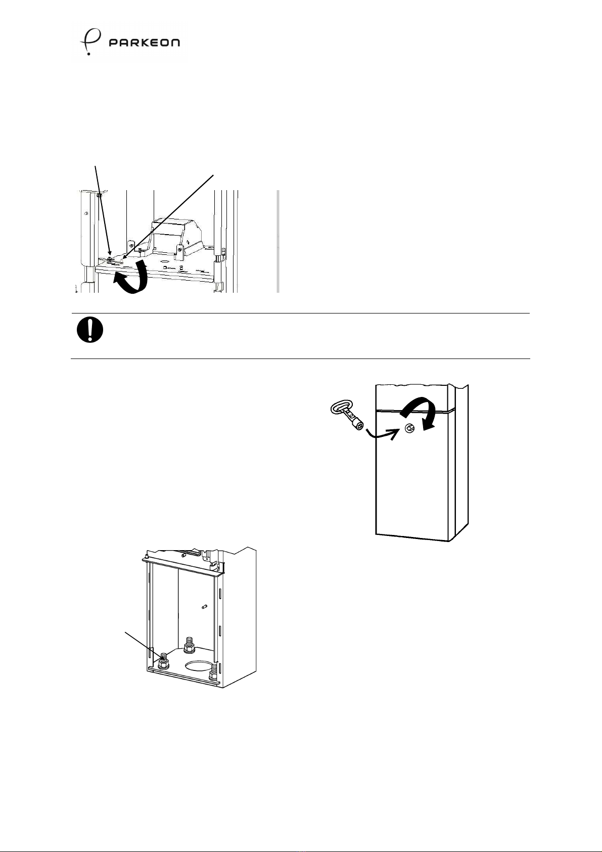
5. Opening the door and trap door ........................................................9
5.1 Configuration with mechanical lock ................................................ 9
5.2 Unlocking the access door ......................................................... 10
6. nchoring in an excavation with a base box ....................................... 11
6.1 Recommendation.................................................................... 11
6.2 Composition of fasteners........................................................... 11
6.3 Excavation installation with base box (1 00 mm high) ........................ 1
6.4 Excavation installation with variable height base box......................... 17
6.5 Excavation installation with base box on sloping ground...................... 1
7. nchoring on flat ground with base box ............................................ 22
7.1 Recommendation....................................................................
7.2 Composition of fasteners...........................................................
7.3 Installation on flat ground with base box (1337 mm high) .................... 3
7.4 Installation on flat ground with base box (1 00 mm high) .................... 7
8. nchoring on flat ground without base box ........................................ 32
8.1 Recommendation.................................................................... 3
8.2 Composition of fasteners........................................................... 3
8.3 Anchoring on flat ground without base box ..................................... 33
9. Installing the upper part of the terminal ........................................... 37
9.1 Parking terminal alone ............................................................. 37
9.2 Terminal with integrated solar module and/or antenna protection......... 37
9.3 Terminal with zone indicator...................................................... 38
9.4 Terminal with integrated solar top and /or antenna cover and zone
indicator ............................................................................. 38
10. pplying the stickers.................................................................... 40
10.1 Sticker plate (CONF1 to CONF14) ................................................. 40
10.2 Zone marking ........................................................................ 41
11. Installing the battery.................................................................... 42

1 - Safety
Strada Evolution - Transfer and Rapide - Installation manual
4 / 4
1.
Safety
Parkeon products are designed to limit the risk to users or operators from power sources, high
temperature, fire, mechanical parts, radiation or chemicals.
The product is compliant with the directive:
Directive 2004/40/EC of the European Parliament and of the Council of 9 April 004 on the
minimum health and safety requirements regarding the exposure of workers to the risks
arising from physical agents (electromagnetic fields).
Follow the basic precautions below for the safety of personnel and the environment. The list is not
comprehensive and is only aimed at drawing your attention to the potential risks of poorly
performed work and negligence:
•All product-servicing operations require appropriate training. Only adequately trained
personnel may work on the mains power supply.
•Wear personal protective equipment suited to the nature of the work to be performed.
•Use appropriate tools that are in good condition, for their intended purpose.
•Mark out the anchoring system in the street while the concrete is setting in order to inform
others of the risk of obstruction. This may be achieved as shown below, providing it is in
accordance with local regulations:
CE Marking
Europe
This product is compliant with the CE marking. The mandatory directives depend on the radio
communication option:
With a radio communication option (GPRS, WIFI, short range devices, …)
The product is compliant with the following standards:
-Directive 1999/5/EC of the European Parliament and of the Council of 9 March 1999
on radio equipment and telecommunications terminal equipment and the mutual
recognition of their conformity.
-Council Recommendation 1999/519/EC of 1 July 1999 on the limitation of exposure
of the general public to electromagnetic fields (0 Hz to 300 GHz).
Without the GPRS option:
The product is compliant with the following directives:
-Directive 2006/95/EC of the European Parliament and of the Council of 1 December
006 on the harmonization of the laws of Member States relating to electrical
equipment designed for use within certain voltage limits.
D3979
D4136

1 - Safety
Strada Evolution - Transfer and Rapide - Installation manual
5 / 4
-Directive 2004/108/EC of the European Parliament and of the Council of 15
December 004 on the approximation of the laws of the Member States relating to
electromagnetic compatibility and repealing Directive 89/336/EEC.
United States of merica
This product is compliant with:
The National Electrical Code
The Americans with Disabilities Act (ADA)
The Federal Communication Commission (FCC) rules part 15
FCC Compliance Statement
This device complies with part 15 of the FCC rules. Operation is subject to the following two
conditions:
1. This device may not cause harmful interference, and
. This device must accept any interference received, including interference that may cause
undesired operation.
Note: The manufacturer is not responsible for any radio or tv interference caused by
unauthorized modifications to this equipment. Such modifications could void the user's
authority to operate the equipment.
Electricity
•All product-servicing operations require appropriate training.
•Only adequately trained personnel may work on the mains power supply.
•Protect personnel from electrical shocks with the help of appropriate electrical and earth
connections.
•Always switch off the power before beginning some repairs, as instructed in this manual.
•Make sure that the electrical parts are installed in accordance with national standards.
•Keep the mains power supply disconnected throughout these operations. Protect the
electrical wires from the rain. Never work on products connected to the mains or the
telephone network during stormy weather.
•While repairing a circuit breaker installed on a machine, the main circuit breaker located in
the technical unit must be switched off and marked with maintenance information so as to
protect the agent from electric shocks.
•Isolate the mains power supply with the circuit breaker and switch off the low-voltage
power with the On/Off button on the main board.
•Make sure that the earth cable is in good condition.
•Follow the instructions relating to the earth connections of product components in order to
ensure compliance with EMC immunity and emissions standards.
•Minimum and maximum diameter of mains power supply cables: 1.5 to .5 mm².
•Ask for a signed certificate from the contractor.

0 -
Strada Evolution - Transfer and Rapide - Installation manual
6 / 4
Mechanical parts
•Always remove any metal jewellery (rings, bangles, bracelets or wristwatches) before
beginning work on or near electrical parts (power supply, battery, wiring) or moving parts.
•Do not bring your hand close to mobile parts, moving parts or sharp parts, door hinges or
locks and pinions or blades.
•Take care to avoid injury by the open door or any other protruding part or part fixed to the
product.
Temperature
•Always wait for a few minutes after switching off the Pay & Display machine before you start
working near the hot areas of the intermittent heating devices.
Dry cells / Batteries
•Always take care to comply with the polarity of batteries and cells.
•Do not obstruct the operating of the lithium cell of the main board. Explosion hazard.
•Never throw away, burn or open the buffer batteries or cells. Use the appropriate procedures
as recommended by the competent health and safety authorities. These elements must be
disposed of in accordance with local regulations.
IMPORT NT:
Parkeon shall not be liable for any modifications to the Pay & Display machine or failure
to use it in accordance with the instructions in this manual.
Environment
The product is compliant with the directives:
•Directive 2002/95/EC of the European Parliament and of the Council of 7 January 003 on the
restriction of the use of certain hazardous substances in electrical and electronic equipment
(ROHS).
•Directive 2002/96/EC of the European Parliament and of the Council of 7 January 003 on
waste electrical and electronic equipment (WEEE).
Disposal of used equipment
The presence of this symbol on the product or packaging means that it may not be disposed of with
ordinary waste.
Products bearing this symbol shall be disposed of using special procedures in accordance with
European Directive 00 /96 on waste electrical and electronic equipment
.

2 - About this document…
Strada Evolution - Transfer and Rapide - Installation manual
7 / 4
2. bout this document…
This document is to be used by personnel responsible for construction and masonry
work.
With a universal power supply, the installation requires the simultaneous presence
of a qualified electrician for the connections and a maintenance agent for the
general installation of the terminal.
These instructions must be followed for optimised terminal installation.
Please refer to the installation manual of the universal mains power supply for
instructions relating to the installation of such power supplies.
Refer to the User manual for general instructions.
Refer to the Maintenance manual for putting into service, troubleshooting and the
replacement of subassemblies.

3 - Tools
Strada Evolution - Transfer and Rapide - Installation manual
8 / 4
3. Tools
Use clean grease-free tools to install the terminal correctly.
Appropriate tooling will be required for correctly installing the removal protection nut.
The following are needed for preparing a terminal:
•door opening tool (ref. 135964),
•square key (ref. 135078),
•ratchet handle,
•16-mm socket.
The following are needed for fastening the terminal on flat ground or in an
excavation:
•rule,
•spirit level,
•4-mm eye type spanner,
•ratchet handle,
•4-mm socket.
The following are needed for installing the upper part of the terminal:
•ratchet handle,
•13-mm socket.
4. Dimensions
Keep minimum clearance around the terminal (30 x 30 cm) to enable movement
during installation and when it is used by motorists:
•0 cm at the rear and on the sides,
•1 metre in front.
Installation in an excavation will require a hole that is 60 cm long x 60 m wide x
60 cm deep, in keeping with the dimensional constraints of the terminal.
The mains cable (optional mains power supply) goes through the centre of the
housing.

5 - Opening the door and trap door
Strada Evolution - Transfer and Rapide - Installation manual
9 / 4
5. Opening the door and trap door
IMPORT NT:
First make sure that the keys to the upper maintenance door are available.
5.1 Configuration with mechanical lock
•Carry the terminal up to the site on its transport pallet.
•Unpack the terminal.
•Open the housing door.
IMPORT NT:
The mechanical lock is protected by guard covers in order to reduce the
risk of vandalism.
Detail ( )
To open the door:
•Insert the key in the lock;
•With the end of the key, push the first cover to the left (1) then the second
one to the right (2);
•When the lock is accessible, insert the key and unlock the door (3).
•Open the maintenance door.
3
1
2
Guard covers
Detail ( )
D8755
D8758

5 - Opening the door and trap door
Strada Evolution - Transfer and Rapide - Installation manual
10 / 4
5.2 Unlocking the access door
•
Unlock the flap that holds the
access door lock.
•Lift the access door lock.
IMPORT NT:
After the parking terminal is installed, lower the access door lock to lock
the door.
•Open the door with the
square key.
•Remove the door.
•Unfasten and remove the
four fastening screws (use a
ratchet handle and a 16-mm
socket).
D8756
ccess door locking flap
ccess door lock
D635
Screws
(x4)

- Anchoring in an excavation with a base box
Strada Evolution - Transfer and Rapide - Installation manual
11 / 4
6. nchoring in an excavation with a base box
6.1 Recommendation
For anchoring in an excavation, Parkeon recommends the following:
•concrete base (B 5),
•minimum concrete thickness 500 mm.
6.2 Composition of fasteners
The parts required are:
Quantity Description Illustration
1 Base box
1 Form
16
(or 1 nuts
with 4 coupling)
M16 nut
Coupling
4 Washer
4 Anchoring rod
1 Anchoring
protection plate
IMPORT NT:
The removal protection nut is not supplied with the excavation fastening
kit, but with the machine.

- Anchoring in an excavation with a base box
Strada Evolution - Transfer and Rapide - Installation manual
1 / 4
6.3 Excavation installation with base box (1200 mm high)
User button height 1 00mm
IMPORT NT: Installation in accordance with standards EN15 91, DDA,
ADA
IMPORT NT:
Cash from a terminal that is installed so that the final height of user buttons is
1 00 mm cannot be collected with a collection trolley.
The form may be used but is not indispensable.
The anchoring protection plate is not used with this installation height.
6.3.1 Preparation
•Prepare the base box with 8 nuts and 4 anchoring rods.
Front of the terminal
Base box
104+/- 1 mm
nchoring
rods
Detail ( )
Detail ( )
D8760

- Anchoring in an excavation with a base box
Strada Evolution - Transfer and Rapide - Installation manual
13 / 4
IMPORT NT:
If a form is being used for installation, install it in the base box.
•Dig a hole measuring 600 x 600 x 600 mm.
500
D611
100
Top of
concrete
Finished ground:
Paving
Concrete etc.
Base box
Form
D8761

- Anchoring in an excavation with a base box
Strada Evolution - Transfer and Rapide - Installation manual
14 / 4
6.3.2 Fastening
•Fill the hole with concrete over a height of 500 mm.
•Set in the base box, pushing the anchoring rods into the concrete (the top of
the base box must be flush with the finished ground level).
•Fill the base box with concrete and level it.
•Comply with the drying time recommended by the concrete supplier.
•Carry out the finishing work up to the ground level. If the ground is to be
finished in concrete or paving stones, you need not wait for the concrete to
set.
•Tighten 4 M16 nuts (or 4 couplings) on the threaded rods up to the base box
level.
•Set the housing on the base box.
D876
D8763

- Anchoring in an excavation with a base box
Strada Evolution - Transfer and Rapide - Installation manual
15 / 4
•Place 4 washers and 4 M16 nuts on the anchoring rods.
•Set the 4 lower M16 nuts in contact with the housing.
•Check if the housing is vertical.
•If the housing is not perfectly vertical, adjust it with the 4 lower nuts (or
couplings).
•Fasten the 4 upper M16 nuts.
Use of removal protection nuts:
•Set the nuts on the threaded rod to the front left and/or the threaded
rod to the rear right.
•Use a 4-mm eye type spanner.

- Anchoring in an excavation with a base box
Strada Evolution - Transfer and Rapide - Installation manual
16 / 4
Installation in accordance with standards EN15291, DD , D
1200
mm
752
mm
D8764

- Anchoring in an excavation with a base box
Strada Evolution - Transfer and Rapide - Installation manual
17 / 4
6.4 Excavation installation with variable height base box
(1 41 mm < user button height < 1337 mm).
IMPORT NT:
The form may be used but is not indispensable.
Depending on the position of the base box in the hole, the final height of
the housing may be adjusted by 96 mm.
6.4.1 Preparation
•Prepare the base box with 8 nuts and 4 anchoring rods (protective plate on
the front of the terminal).
IMPORT NT:
If a form is being used for installation, install it in the base box.
Base box
104+/- 1 mm
nchoring
rods
Detail ( )
Detail ( )
D8930
nchoring
protection plate
Front view
Front of the terminal
Base box
Form
D8931
nchoring
protection plate

- Anchoring in an excavation with a base box
Strada Evolution - Transfer and Rapide - Installation manual
18 / 4
•Dig a hole measuring 600 x 600 x 600 mm.
6.4.2 Fastening
•Fill the hole with concrete over a height of 500 mm.
•Set in the base box, pushing the anchoring rods into the concrete.
•Fill the base box with concrete (fill the base box according to its position in
the hole) and level it.
Check that the holes for letting water out of the base box are not
blocked.
Example 1 Example 2 Example 3
500
D611
100
Top of
concrete
Finished ground:
Paving
Concrete etc.
Draining holes
106
59
202
155
108
D8934
D8933
100
96
155
D893
100

- Anchoring in an excavation with a base box
Strada Evolution - Transfer and Rapide - Installation manual
19 / 4
•Comply with the drying time recommended by the concrete supplier.
•Carry out the finishing work up to the ground level. If the ground is to be
finished in concrete or paving stones, you need not wait for the concrete to
set.
•Fasten 4 M16 nuts (or 4 couplings) on the threaded rods (1 mm above the
base box) and level them.
•Set the housing on the M16 nuts.
•Place 4 washers and 4 M16 nuts on the anchoring rods.
•Check if the housing is vertical.
•If the housing is not perfectly vertical, adjust it with the 4 lower nuts (or 4
lower couplings).
•Fasten the 4 M16 nuts.
IMPORT NT:
Use of removal protection nuts:
•Set the nuts on the threaded rod to the front left and/or the threaded
rod to the rear right.
•Use a 4-mm eye type spanner.
12 mm
D8935
nchoring protection plate
Pedestal

- Anchoring in an excavation with a base box
Strada Evolution - Transfer and Rapide - Installation manual
0 / 4
Depending on the position of the base box in the ground (installation depth), the
height of the user buttons may thus be 1 41 mm (with finished ground 1), 1300 mm
(with finished ground ) or 1337 mm (with finished ground 3).
Finished
ground 1
Finished
ground 2
Finished
ground 3
D8936
This manual suits for next models
1
Table of contents
Other Parkeon Digital Signage manuals