iii
TABLE OF CONTENTS
Chapter 1
Getting Started ..................................................................................................................1
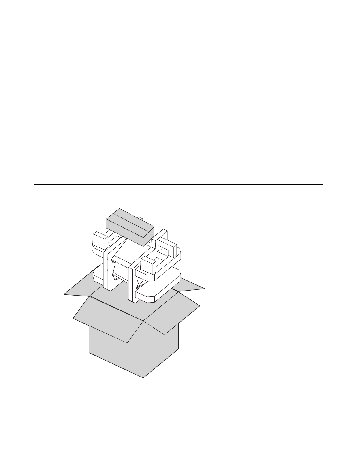
Unpacking the PT-5500 ...................................................................................................................... 1
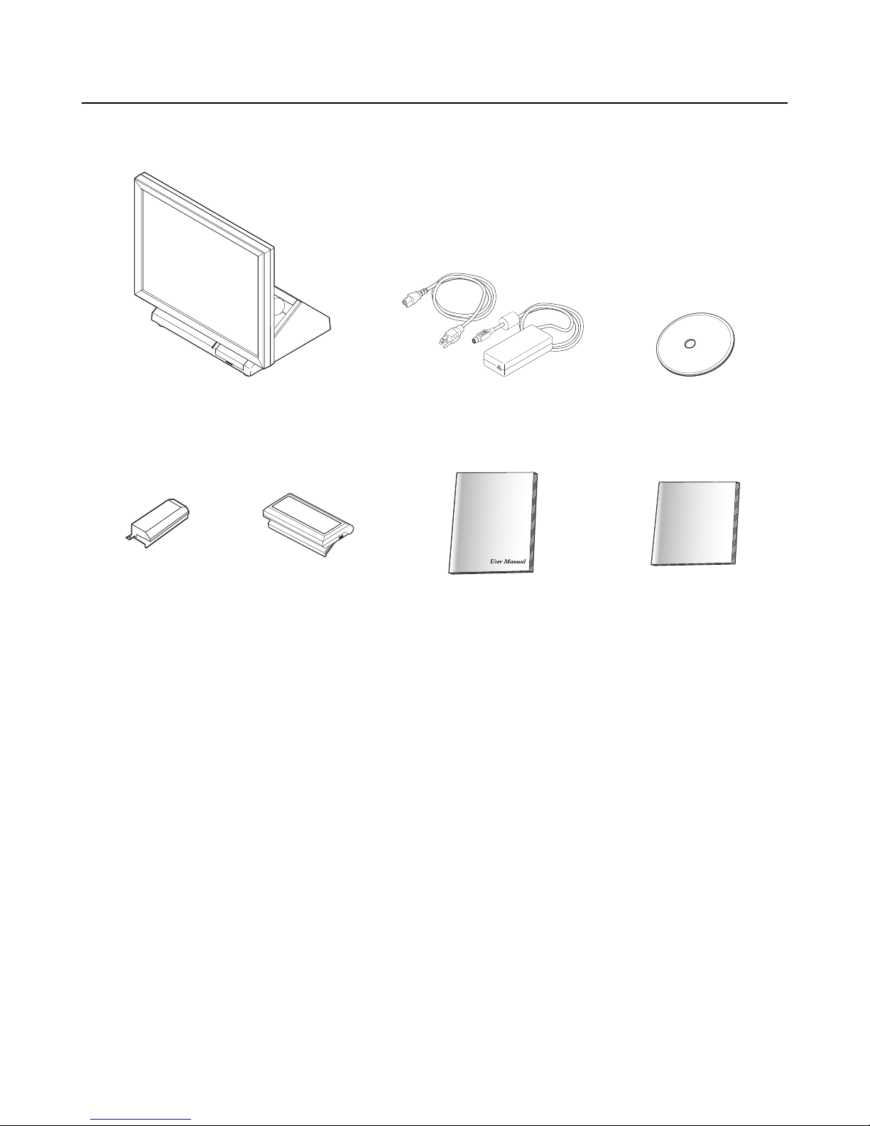
Checking the package contents ........................................................................................................... 2
Identifying components ...................................................................................................................... 3
Front-right view ................................................................................................................................................. 3
Rear-right view .................................................................................................................................................. 4
Rear connectors ................................................................................................................................................. 5
Removing the rear cover ..................................................................................................................... 6
Attaching the customer display ........................................................................................................... 7
Adjusting display angles ..................................................................................................................... 8
Setup considerations ........................................................................................................................... 9
Connecting peripheral devices ............................................................................................................ 9
Powering the PT-5500 on and off ..................................................................................................... 10
Chapter 2
Upgrading Components ..................................................................................................11
Safety and precautions ...................................................................................................................... 11
Before you begin ............................................................................................................................... 12
Installing a hard disk drive (HDD) ................................................................................................... 12
Installing a CompactFlash card ......................................................................................................... 13
Chapter 3
BIOS Setup Utility .........................................................................................................15
About the Setup Utility ..................................................................................................................... 15
Entering the Setup Utility ................................................................................................................................ 16
BIOS navigation keys ....................................................................................................................................... 16
Using BIOS ..................................................................................................................................................... 17
Standard CMOS features .................................................................................................................. 17
IDE Primary/Secondary Master/Slave ........................................................................................................... 17
Advanced BIOS Features ................................................................................................................. 19
Advanced Chipset Features ............................................................................................................................. 21
DRAM Clock/Drive Control ............................................................................................................................ 22
AGP & P2P Bridge Control ............................................................................................................................ 24
CPU & PCI Bus Control ................................................................................................................................. 25
Integrated Peripherals ...................................................................................................................... 26
VIA OnChip IDE Device .................................................................................................................................. 27
VIA OnChip PCI Device .................................................................................................................................. 28
SuperIO Device ................................................................................................................................................ 29
Power Management Setup Option .................................................................................................... 30
PnP/PCI Configurations .................................................................................................................................. 33
PC Health Status .............................................................................................................................................. 35
Frequency/Voltage Control ............................................................................................................... 36
Other BIOS Options ......................................................................................................................................... 37
Load Fail-Safe Defaults Option ....................................................................................................................... 37