PASCO //code.Node User manual

Product Manual
012-16652A
800-772-8700 www.pasco.com
//code.Node
PS-3231
Included Equipment
1
//code.Node
2
Micro USB cable
For connecting the sensor to a USB charger to
charge the battery or a USB port to transmit data.
Required Equipment
PASCO Capstone or SPARKvue software is required for
data collection
Overview
The //code.Node is an input-output device that supports coding activities to help teach how sensors work and how code can
be used to create and control a response (output) to a stimulus (input). The //code.Node is an introductory device for STEM
oriented programming activities performed using PASCO software applications. The device contains five sensors and two
momentary push buttons that act as inputs as well as three output signals, enabling students to program how the device
collects and responds to data.
The //code.Node can sense relative light brightness, relative sound loudness, temperature, acceleration, tilt angle, and
magnetic field. These input sensors are included to help teach coding concepts and highlight how collected data can be
analyzed and programmed to create unique outputs involving its speaker, LED light source, and 5 x 5 LED array. The
//code.Node outputs are not exclusive for use only with its inputs; the outputs can be used in code involving any PASCO
sensors and interfaces.
The //code.Node sensors are meant to be used for coding purposes and should not be considered a replacement for science
sensors in labs that use similar sensor measurements; science sensors built to more rigorous specifications for use in
science experiments are available at www.pasco.com.

PS-3231 //code.Node
012-16652A
INPUTS
1
Magnetic Field Sensor
2
Acceleration Sensor and Tilt
3
Light Sensor
4
Ambient Temperature Sensor
5
Sound Sensor
6
Button 1 and Button 2
OUTPUTS
A
Red-Green-Blue (RGB) LED
B
Speaker
C
5 x 5 LED Array
SENSOR COMPONENTS
7
Power button
Press and hold for one second to turn on or off.
8
Battery status LED
Red blink
Battery needs to be recharged soon.
Green solid
Battery is fully charged
Yellow solid
Battery is charging.
9
Micro USB port
For charging the battery when connected to a USB
charger. For transmitting data when conencted to the
USB port of a computer.
10
Bluetooth status LED
Red blink
Ready to be paired with software
Green blink
Paired with software.
11
Sensor ID
Use this ID when connecting the sensor to software.
12
Lanyard Hole
For attaching a lanyard, string, or other material.

PS-3231 //code.Node
012-16652A
//code.Node Inputs
Temperature/Light/Sound Sensor
NOTE: The Temperature, Light, and Sound Sensors
are not calibrated and cannot be calibrated within
PASCO software
This 3-in-1 sensor records ambient temperature,
brightness as a measure of relative light intensity, and
loudness as a measure of relative sound level.
•The temperature sensor measures ambient
temperature between 0 –40 °C.
•The light sensor measures brightness on a 0 –
100% scale, where 0% is a dark room and 100%
a sunny day.
•The sound sensor measures loudness on a 0 –
100% scale, where 0% is background noise (40
dBC) and 100% is a (very, very) loud scream
(~120 dBC).
Magnetic Field Sensor
The magnetic field sensor only measures the strength of
a magnetic field in the y-axis. A positive strength is
produced when the north pole of a magnet it moved
towards the “N” in the magnetic field sensor icon on the
//code.Node.
While the magnetic field sensor cannot be calibrated in
the software application, the sensor measurement can be
tared to zero.
Button 1 and Button 2
Button 1 and Button 2 are included as basic momentary
inputs. While pressed the Button will be assigned a value
of 1. A value of 0 is assigned when the button is not being
pressed.
Acceleration Sensor and Tilt
The acceleration sensor within the //code.Node measures
acceleration in the x- and y- axis directions, which are
labelled on the sensor icon shown on the device. The
pitch (rotation around the y-axis) and roll (rotation around
the x-axis) are measured as Tilt Angle -x and Tilt Angle -
y respectively; the tilt angle is measured to a ± 90° angle
in relation to the horizontal and vertical planes.
The acceleration and tilt angle measurements of the
sensor can be tared to zero from within the software
application
When placed face-up on a flat surface, tilting the
//code.Node left (thus rotating around the y-axis) will
result in a positive x- acceleration and a positive x- tilt
angle up to 90°. Tilting to the right will result in a negative
x- acceleration and negative x- tilt angle. Similarly, tilting
the device upwards (rotating around the x axis) will result
in a positive y- acceleration and positive y- tilt angle to a
max angle of 90°; tilting the device downwards will
produce negative values.

PS-3231 //code.Node
012-16652A
//code.Node Outputs
Within the Blockly-integrated Code tool, unique coding blocks have been created in SPARKvue and PASCO Capstone for
each output of the //code.Node to program and control their effects.
NOTE: The use of the //code.Node outputs are not exclusive to its inputs. These outputs can be used in conjunction with
all lines of supported PASCO sensors.
To access and use the Code Blocks for the //code.Node:
(Must be version 2.1.0 or later)
1. Open PASCO Capstone and select Hardware
Setup from the Tools panel on the left.
2. Connect the //code.Node to the computer.
3. On the Tools tab, select Code.
4. Select “Hardware” from the list of Blockly
Categories.
(Must be version 4.4.0 or later)
1. Open SPARKvue and select Sensor Data from
the Welcome Screen.
2. Connect the //code.Node to the device.
3. Once the //code.Node measurements appear,
select a template option.
4. Click the Code button on the bottom toolbar.
5. Select “Hardware” from the list of Blockly
Categories.
RGB LED
One output signal of the //code.Node is its Red-Green-
Blue (RGB) multi-color LED. The individual brightness
levels for red, green, and blue light of the LED can be
adjusted from 0 –10, allowing for a spectrum of colors to
be created.
A single block is included in Code for the RGB LED (1)
and can be found in the Hardware Blockly category. A
brightness of ‘0’ will ensure that that selected color LED
is not emitted.
(1)
Speaker
While the volume is fixed, the frequency of the
//code.Node Speaker can be adjusted using the
appropriate Code blocks. The speaker can generate
sounds within a range of 0 –20,000 Hz.
Two unique blocks are included in the software’s Code
tool to support the speaker output: one turns the speaker
on or off (2) and one sets the frequency (3).
(2)
(3)
5 x 5 LED Array
The central output of the //code.Node is a 5 x 5 array
consisting of 25 red LEDs. The LEDs in the array are
positioned using the (x,y) Cartesian coordinate system,
with (0,0) at the top left corner and (4,4) at the lower right
corners. A faint imprint of the corner coordinates can be
found at each corner of the 5 x 5 LED Array on the
//code.Node.
The LEDs in the array can be turned on individually or as
a set. The brightness of the LEDs is adjustable on a scale
of 0 –10, where a value of 0 will turn the LED OFF.
Three unique blocks are included in the software’s Code
tool that support the 5 x 5 LED Array. One block sets the
brightness of a single LED at a specified coordinate (4).
Another block will set a group of LEDs to a specified
brightness level and can be programmed to keep or clear

PS-3231 //code.Node
012-16652A
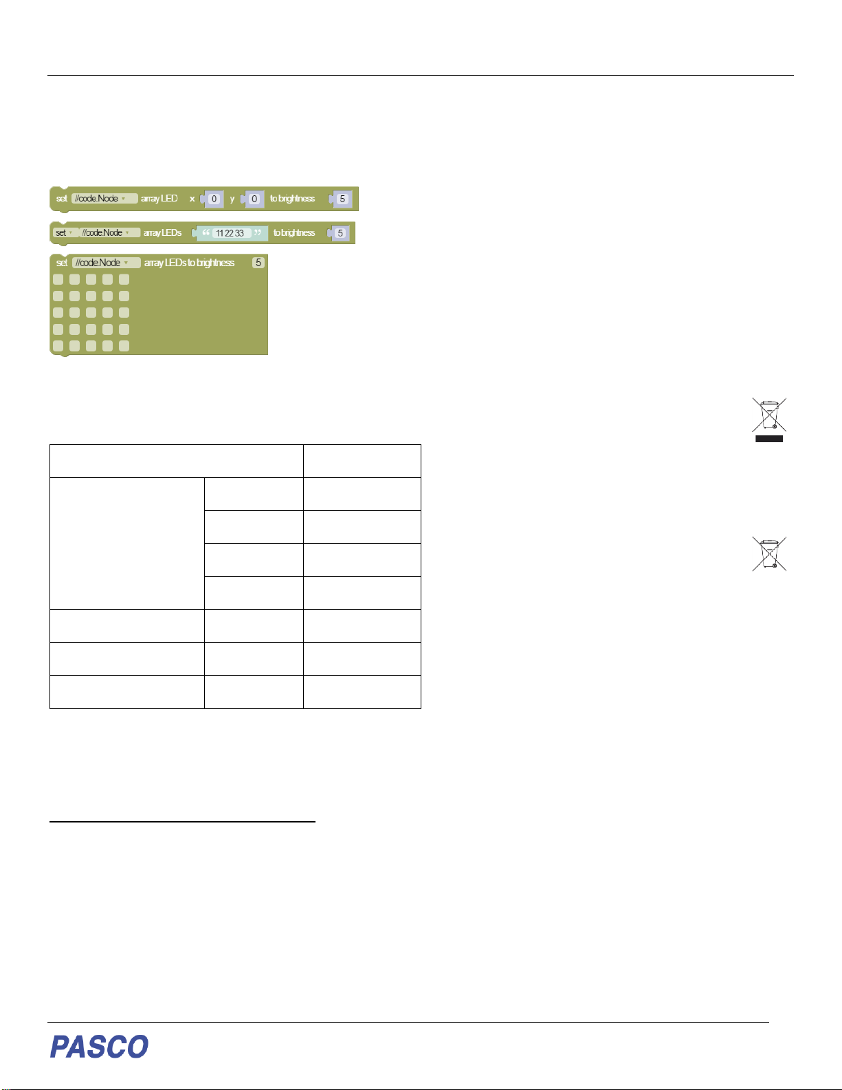
previous code commands concerning the 5 x 5 LED Array
(5). A third block is an imitation of the 5 x 5 array on the
//code.Node (6); checking a square is equivalent to setting
the LED at that position on the //code.Node array to the
specified brightness. Multiple squares can be selected.
(4)
(5)
(6)
Specifications of Sensors
Experiments
Copy-ready experiment worksheets for classroom use
are available on the PASCO website. Download the
experiments for free at:
www.pasco.com/resources/lab-experiments
Technical Support
For assistance with PASCO products, contact PASCO at:
Address:
PASCO scientific
10101 Foothills Blvd.
Roseville, CA 95747-7100
Phone:
916-462-8384
Chat:
www.pasco.com
Email:
Product End of Life Disposal Instructions
This electronic product is subject to disposal and recycling regulations
that vary by country and region. It is your responsibility to recycle your
electronic equipment per your local environmental laws and regulations
to ensure that it will be recycled in a manner that protects human health
and the environment. To find out where you can drop off your waste
equipment for recycling, please contact your local waste
recycle/disposal service, or the place where you purchased the product.
The European Union WEEE (Waste Electronic and Electrical
Equipment) symbol (to the right) and on the product or its
packaging indicates that this product must not be disposed of
in a standard waste container.
Battery Disposal Instructions
Batteries containchemicals that, if released, may affect the environment
and human health. Batteries should be collected separately for recycling
and recycled at a local hazardous material disposal location adhering to
your country and local government regulations. To find out where you
can drop off your waste battery for recycling, please contact your local
waste disposal service, or the product representative. The
battery used in this product is marked with the International
symbols to indicate the need for the separate collection and
recycling of batteries.
FCC Statement
This Class A digital device complies with part 15 of the FCC Rules.
Operation is subject to the following two conditions: (1) This device may
not cause harmful interference, and (2) this device must accept any
interference received, including interference that may cause undesired
operation.
CE Statement
This device has been tested and found to comply with the essential
requirements and other relevant provisions of the applicable EU
Directives.
Warranty, Copyright, and Trademarks
Limited Warranty For a description of the product warranty, see the
Warranty and Returns page at www.pasco.com/legal.
Copyright This document is copyrighted with all rights reserved.
Permission is granted to non-profit educational institutions for
reproduction of any part of this manual, providing the reproductions are
used only in theirlaboratories andclassrooms, and are not sold for profit.
Reproduction under any other circumstances, without the written
consent of PASCO scientific, is prohibited.
Trademarks PASCO and PASCO scientific are trademarks or
registered trademarks of PASCO scientific, in the United States and/or
in other countries. All other brands, products, or service names are or
may be trademarks or service marks of, and are used to identify,
products or services of, their respective owners. For more information
visit www.pasco.com/legal.
//code.Node max sampling rate
50 Hz
Temperature
Range
0 –40 °C
Units
°C, °F, K
Resolution
0.125 °C
Accuracy
± 2 °C
Magnetic Field
Range
± 50 Gauss
Acceleration (x and y)
Range
± 8 g
Tilt Angle (x and y)
Range
± 90°

www.pasco.com
Using the sensor for the first time
The following instructions are intended for SPARKvue users. If you are using PASCO Capstone, follow the instructions on
the opposite side of this page.
Before using the sensor in the classroom, do the following: (1) charge the battery, (2) install the latest version of SPARKvue,
(3) update the sensor firmware. Installing the latest version of SPARKvue and sensor firmware is necessary to have access
to the latest features and bug fixes. Detailed instructions for each procedure are provided below.
Update the sensor firmware
Sensor firmware is installed using SPARKvue. You must install the latest version of SPARKvue in order to have access to
the latest version of the sensor firmware. When you connect the sensor to SPARKvue, you will automatically be notified if
a firmware update is available. Click Yes to update the firmware when prompted. If you do not receive a notification, the
firmware is up to date.
Tip: Connect the sensor using USB for a faster firmware update.
Charge the battery
The sensor contains a rechargeable battery. A fully
charged battery will last an entire school day. To charge
the battery:
1. Connect the USB cable to the USB port located on
the sensor.
2. Connect the other end of the cable to a USB charger.
3. Connect the USB charger to a power outlet.
As the device is charging, the battery indicator light will be
yellow. The device is fully charged when the light is green.
Install the latest version of SPARKvue
Follow the instructions below for your device to download
and install the latest version of SPARKvue.
Windows and macOS
Go to www.pasco.com/downloads/sparkvue then click
Download Update.
iOS and Android
Search for SPARKvue in the App Store (iOS) or Google
Play Store (Android).
Chromebook
Search for SPARKvue in the Chrome Web Store.
Connect the sensor to SPARKvue
The sensor can be connected to SPARKvue using a USB
or Bluetooth connection.
Note: Connecting using USB is not available with iOS
devices and some Android devices.
To connect using USB:
1. Connect the USB cable to the USB port of the sensor.
2. Connect the other end of the cable to your device.
3. Open SPARKvue.
To connect using Bluetooth:
1. Turn on the sensor by pressing and holding the power
button for one second.
2. Open SPARKvue.
3. Select Sensor Data.
4. Select the wireless sensor that matches the ID
labeled on your sensor.

www.pasco.com
Using the sensor for the first time
The following instructions are intended for PASCO Capstone users. If you are using SPARKvue, follow the instructions on
the opposite side of this page.
Before using the sensor in the classroom, do the following: (1) charge the battery, (2) install the latest version of Capstone,
(3) update the sensor firmware. Installing the latest version of Capstone and the sensor firmware is necessary to have
access to the latest features and bug fixes. Detailed instructions for each procedure are provided below.
Update the sensor firmware
Sensor firmware is installed using Capstone. You must install the latest version of Capstone in order to have access to the
latest version of the sensor firmware. When you connect the sensor to Capstone, you will automatically be notified if a
firmware update is available. Click Yes to update the firmware when prompted. If you do not receive a notification, the
firmware is up to date.
Tip: Connect the sensor using USB for a faster firmware update.
Charge the battery
The sensor contains a rechargeable battery. A fully
charged battery will last an entire school day. To charge
the battery:
1. Connect the USB cable to the USB port located on
the sensor.
2. Connect the other end of the cable to a USB charger.
3. Connect the USB charger to a power outlet.
As the device is charging, the battery indicator light will be
yellow. The device is fully charged when the light is green.
Install the latest version of PASCO Capstone
PASCO Capstone is available for computers running
Windows or macOS. To download the latest version, go
to www.pasco.com/downloads/capstone then click
Download Update.
Connect the sensor to PASCO Capstone
The sensor can be connected to Capstone using a USB
or Bluetooth connection.
To connect using USB:
1. Connect the USB cable to the USB port of the sensor.
2. Connect the other end of the cable to your device.
3. Open Capstone.
To connect using Bluetooth:
1. Turn on the sensor by pressing and holding the power
button for one second.
2. Open Capstone.
3. Click Hardware Setup in the Tools panel on the left
side of the screen.
4. Click the wireless sensor that matches the ID labeled
on your sensor.
This manual suits for next models
1
Table of contents