manuals.online logo
Brands
  1. Home
  2. •
  3. Brands
  4. •
  5. Passione 3D
  6. •
  7. Toy
  8. •
  9. Passione 3D MB339 User guide

Passione 3D MB339 User guide

MB339 – Mounting instruction
 Materials / items required for assembly:
- Bonding/glue: Cyanoacrylate medium, activator for cyanoacrylate and cyan spouts dispensers;
- Finishing sandpaper 500/3 0
- Carbon tube diameter 8 mm
- Carbon tube diameter 4 mm
- Carbon tube diameter mm
- Alcol etilico
- Ethyl alcohol
- Cloth for ethyl alcohol (for cleaning surfaces to be bonded)
 Preparative surfaces before bonding:
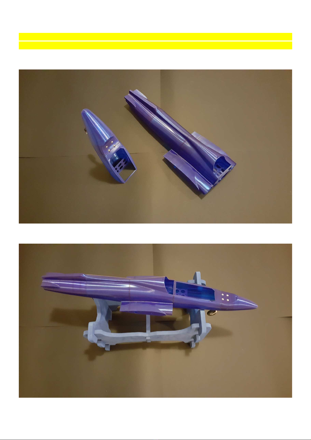
The MB339 model is composed of several sections, which need to be glued together
Each section before being glued must be sanded very quickly to further refine the plan already created by
the press, so that it is smooth and free of debris that might not do well pave surfaces. (Use abrasive paper
500/3 0).
Afterwards degrease with cloth soaked in ethyl alcohol the surfaces before bonding.
The above operations are very fast to perform, are indications to make the perfect job for the KIT assembly.
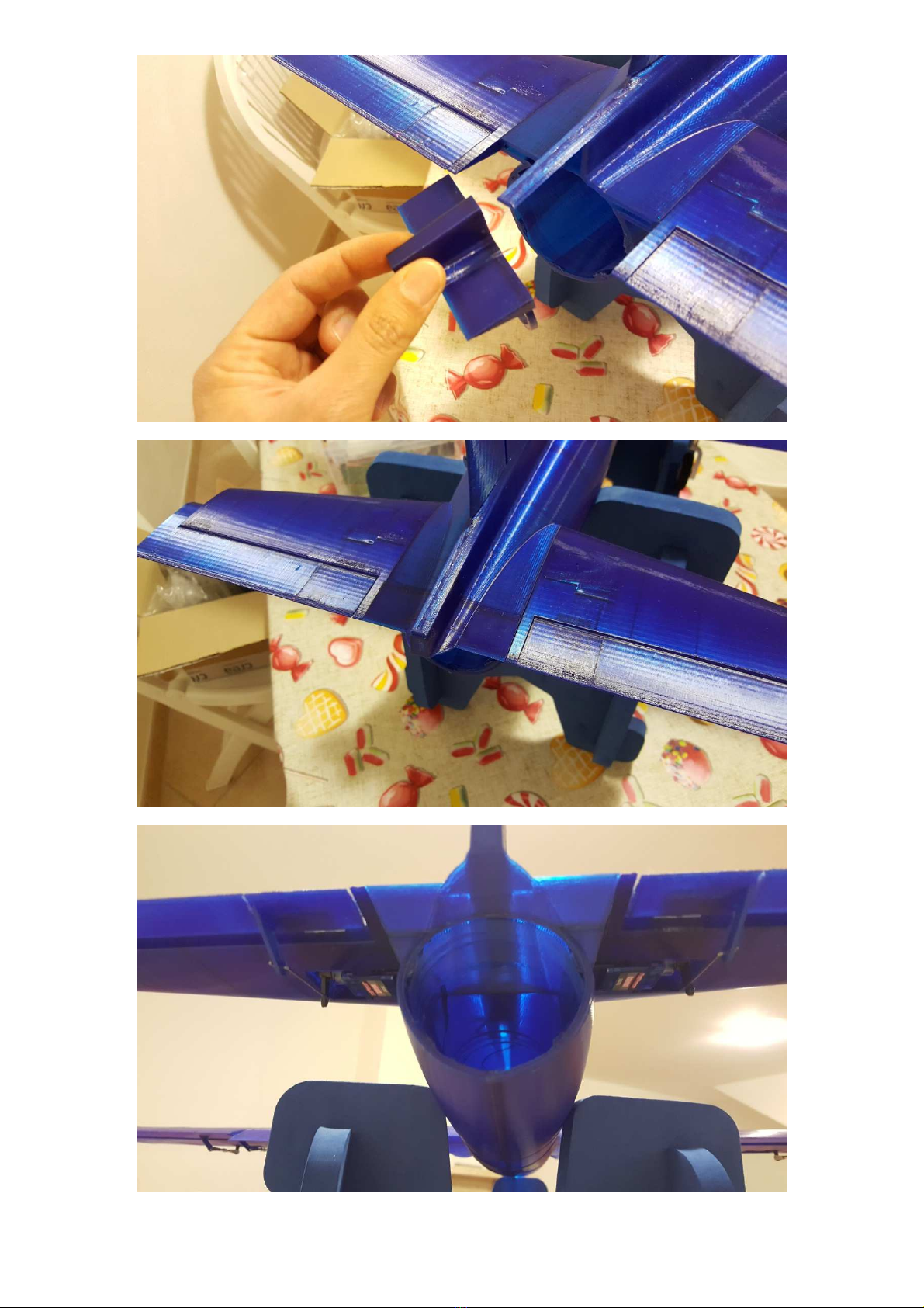
Use the cyanoacrylate medium to glue the sections between them, to avoid frittering of glue, use the cyan
spouts dispensers for medium cyan and apply the glue in the edge inside of the plane (not to exaggerate
with the amount, the cyanoacrylate on this type of materile has a strong seal and performs as a weld
between the glued parts) use the activator to accelerate the drying of the glue. It is important to use the
activator and nebulize in small quantities to avoid too rapid drying of the glue.
Once pasted section, in the inner part of the fuselage wipe across the board always with cyanoacrylate
medium, the sections have been designed to allow the creation of this bonding also internally in the fuselage.
For facilitate the gluing of fusolsgr, divide the fuselage into two parts as in the following picture:
And then successively glue the two sections as follows:
A practical tip is to drilling the first front section for the front carriage before gluing, see the following photo:
In the particular photo of the assembly of the front retractable machine.
N.B. The kit used by Turnigy for reach trucks has a 45mm diameter wheel on the front landing gear, I
recommend replacing it with a 40mm diameter wheel to give the model the right trim. I also recommend
changing the shock absorber spring because it is very stiff and tends to make the nose bounce too much, so
I recommend using a softer one (in any case, you can still try with the original spring, then consider changing
it).
 Assembly of the wings :
Before inserting and gluing the wing sections, I recommend drilling the holes to screw the machines onto
the wing section. It is very important to use a flat head screw of the right length in order to use the entire
internal thickness of the wing where there is the structure that guarantees the right seal to the machine
and the correct anchorage of the carriage. Use screws max 3.5x 5 mm.
Before screwing the machine, insert a washer between the wing hole and the machine, in order to correctly
align the machine with the surface of the wing (see red circles in the photo above).
For convenience, also screw the servos into the housing in the wing, use the cable gland inside the wing for
the wires.
Once the assembly of the two wings is complete, insert them in the central section of the fuselage using a
carbon tube with a diameter of 8mm with a length of 75 cm, and use a carbon tube with a diameter of
mm for the coupling and alignment of the wing, see example in the photo:
The 8mm carbon shaft naturally passes through and takes both wings, if the tube does not pass well in the
hole in the main section, use an 8mm iron drill bit to widen the hole (carbon rods are not all the same, so
the hole can consequently be too precise)
While as regards the mm carbon tube, it must not pass through and must be inserted up to the internal
housing of the main section, in order to avoid it being forward of the fan mouth. The mm tube is
only.used for aligning the wings with respect to the fuselage.
Carbon tube
2mm
C
arbon
tube
8mm
As reported in the previous photo, it is very important to glue all the sections of the wings together and also
on the support surface of the central section of the fuselage, this guarantees the correct functioning of the
whole structure of the wing. servos / landing machines are guaranteed by the internal passage of the cables
in the wing, so there is no need to disassemble the wing.
- Assembly of moving parts :
All the moving parts of the model are designed to house the nylon hinges type 16x 8.5 or alternatively also
the elastic ribbon ones, below a series of illustrative photos:
N.B. lue the wing sections
together and also on the
fuselage with medium cyan
Hinge detail for top photo above and hinge detail wing photo below.
The gluing of the hinges can also be reinforced from the lower part of the moving parts
Glue the two section
s of the
ailerons
 Assembly of elevation plane and rudder:
For the mounting of the platforms and the rudder, a 4mm diameter carbon tube (which will pass through
both shelves) and a mm diameter tube which will only be used exclusively for aligning the parts to the
rest of the fuselage, therefore not passing through, are required, see photo:
All parts must be glued together successively with medium cyan.
Aileron and flap glued and aligned
The brackets are already printed on the moving parts, it
is only
necessary to prepare the
servo
tie rod
Carbon tube diameter 4 mm also for the rudder section.
 Motor assembly : it is recommended to install the motor before assembling the elevation plans
The engine is housed immediately after the center section of the fuselage and is accessible from a screwed
panel under the fuselage. The model is designed for 70mm fans, so it can accommodate different types. The
fan is installed by simply screwing in screws.
The venturi exhaust pipe is supplied in the model kit and consists of two telescopic sections to allow easy
insertion inside the fuselage, once inserted the two sections can be glued together.
Venturi tube
Venturi tube extended ( example with fan)
Venturi tube inserted inside the fuselage
Venturi tube cut flush with the fuselage
Detail of rear tube venturi (example with vemotec fan)
Housing of the engine unit inside the fuselage
Motor unit with detail of air intake and regulator installation.
Closing the motor access hatch (screw diameter mm and screw head maximum diameter 3.5mm)
Focus on the fan assembly inside the fuselage
 Front servo support :
Install the servo base for the rotation of the front leg as in the photo:
Possible battery locking system with strap. It is recommended to insert a soft sponge-like shim under
the battery to avoid keeping the battery dead weight on the rib support.
 C model :
CG : 74,50 mm
 Decals PAN :
Moving parts setting
Rudder : ±18mm
Elevator : ±10mm
Aileron : ±8mm

Other Passione 3D Toy manuals

Passione 3D MB339 edf 90mm User guide

Passione 3D

Passione 3D MB339 edf 90mm User guide

Popular Toy manuals by other brands

Fisher-Price CATERPILLAR 73260 Owner's manual & assembly instructions

Fisher-Price

Fisher-Price CATERPILLAR 73260 Owner's manual & assembly instructions

Hasbro Transformers: Rise of the Beasts Movie Beast Alliance Beast Weaponizers 2-Pack Optimus... manual

Hasbro

Hasbro Transformers: Rise of the Beasts Movie Beast Alliance Beast Weaponizers 2-Pack Optimus... manual

Eduard 644032 quick guide

Eduard

Eduard 644032 quick guide

marklin Postwagens user manual

marklin

marklin Postwagens user manual

Matador Galleon 327 instructions

Matador

Matador Galleon 327 instructions

E-DOMODEL YAK54 Assembly instructions

E-DOMODEL

E-DOMODEL YAK54 Assembly instructions

Excalibur Motorized Bumper Boat with Squirt Gun... owner's manual

Excalibur

Excalibur Motorized Bumper Boat with Squirt Gun... owner's manual

Phoenix Model EXTRA 330SC instruction manual

Phoenix Model

Phoenix Model EXTRA 330SC instruction manual

Carson T78 "Catherine" instruction manual

Carson

Carson T78 "Catherine" instruction manual

VQ Airacobra P-39 instruction manual

VQ

VQ Airacobra P-39 instruction manual

Smoby 720618 manual

Smoby

Smoby 720618 manual

THE WORLD MODELS Super Chipmunk-90 RF instruction manual

THE WORLD MODELS

THE WORLD MODELS Super Chipmunk-90 RF instruction manual

MTHTrains Rail King SW-1 Diesel Engine Operator's manual

MTHTrains

MTHTrains Rail King SW-1 Diesel Engine Operator's manual

Fisher-Price X3050 Owner's manual with assembly instructions

Fisher-Price

Fisher-Price X3050 Owner's manual with assembly instructions

MS Composit SWIFT MAXI Assembly instructions

MS Composit

MS Composit SWIFT MAXI Assembly instructions

Eduard ZOOM FE 992 quick start guide

Eduard

Eduard ZOOM FE 992 quick start guide

Fisher-Price W3131 manual

Fisher-Price

Fisher-Price W3131 manual

REVELL Northrop HAWK weapon system Assembly manual

REVELL

REVELL Northrop HAWK weapon system Assembly manual

manuals.online logo
manuals.online logoBrands
  • About & Mission
  • Contact us
  • Privacy Policy
  • Terms and Conditions

Copyright 2025 Manuals.Online. All Rights Reserved.